MODEL V1433XL, V1433 MODEL V1833XL, V1833 - MinnPar
MODEL V1433XL, V1433 MODEL V1833XL, V1833 - MinnPar
MODEL V1433XL, V1433 MODEL V1833XL, V1833 - MinnPar
- No tags were found...

Create successful ePaper yourself
Turn your PDF publications into a flip-book with our unique Google optimized e-Paper software.
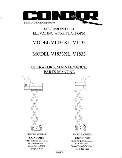
TIME CONDOR CorporationSELF-PROPELLEDELEVATING WORK PLATFORM<strong>MODEL</strong> <strong><strong>V1433</strong>XL</strong>, <strong>V1433</strong><strong>MODEL</strong> <strong><strong>V1833</strong>XL</strong>, <strong>V1833</strong>OPERATORS, MAINTENANCE,PARTS MANUALSHIPPING ADDRESSCONDOR®TIME CONDOR Corporation8300 IMPERIAL DRIVEVVAco,TEXAs76712(254)420-5200MANUAL 92370November 1997MAILING ADDRESSCONDOR®TIME CONDOR CorporationP.O. Box 21447VVACO, TEXAS 76702-1447(254)420-5200
TIME CONDOR CorporationSELF-PROPELLEDELEVATING WORK PLATFORM<strong>MODEL</strong> <strong><strong>V1433</strong>XL</strong>, <strong>V1433</strong><strong>MODEL</strong> <strong><strong>V1833</strong>XL</strong>, <strong>V1833</strong>OPERATOR SECTIONSHIPPING ADDRESSCONDOR®TIME CONDOR Corporation8300 IMPERIAL DRIVEVVAco,TEXAS76712(254)420-5200MAILING ADDRESSCONDOR®TIME CONDOR CorporationP.O. Box 21447VVAco,TEXAS76702-1447(254)420-5200MANUAL 92370-001November 1997
F. DECK EXTENSIONB. RAMP MEmOD•Lift lockpin, at right side of deck, and pushextension deck forward (or out). When fullyextended, lockpin will automatically lock. Toretract, lift lockpin and pull extension deck all theway back untillockpin automatically locksextension deck in place.CAUTIONDo not lower extension deck ontopeople or any objects!G. 'REMOVABLE' UPPER CONTROLBOXUnsnap overcenter latch at bottom of uppercontrol box and pull plug out of receptacle. Bendcable so that plug faces down. Snap cover ontoreceptacle at bottom of box. Lift box and store itin a secure place to prevent unauthorized use ofthe CONDOR®.III. MOVING FROM JOB-SITE TOJOB-SITEA. LOADING AND UNLOADINGAlthough this CONDOR® is somewhat smallcompared with larger construction equipment, itrequires the same care and attention in loading,transporting, and unloading. At no time should itssize,or weight be under estimated. Beforeloading or unloading, inspect the CONDOR® forany physical damage or defects.The means by which you load or unload theCONDOR® should be of sufficient strength towithstand its weight.<strong>MODEL</strong> WEIGHT(#) WEIGHT(KG)<strong>V1433</strong>1XL 2,200Ibs. 998 kg<strong>V1833</strong>1XL 2,400Ibs. 1089 kgEnsure that the ramp is sufficiently strong tosupport the weight ofthe CONDOR®.The ramp should be set, not steeper than thisCONDOR®'s rated gradeability, which for Model<strong>V1433</strong>1XL, <strong>V1833</strong>1XL is 14° or 25%, or a rise of30 inches in a run of 10 feet.Before driving the CONDOR® on a ramp, lowerthe platform completely, test the drive/steercontrols and the brake system.CAUTIONSelect "low" drive speed,not "high" and not "creep".The front of the CONDOR® should be uphill,meaning: Drive forward uphill and reversedown.Keep CONDOR® in alignment with the rampduring loading and unloading procedures.C. FORKLIFT LOADING ANDUNLOADING METHODEnsure that the forklift has sufficient capacity tohandle the weight of this CONDOR®.This CONDOR® can be lifted from the rear,using the forklift pockets provided.NOTE THAT THE CENTER OF GRA VlTYIS 50 INCHES FROM THE END OF THECONDOR®.The CONDOR® should only be raised to a heightsufficient to clear any obstructions.Keep forklift travel to a minimum, carryCONDOR® as close as possible to the ground,and set it down gently.MANUAL 92370-001November 1997
• D.TRANSPORTINGThis CONDOR® can be easily transportedbetween job-sites ifthe following rules andprocedures are followed:Block all wheels to prevent forward and reversemotion.Tie down the CONDOR® with chains or cables,running them through the tie-down holes only. Donot tie down over the guardrails or entry steps.Always tum the power 'off at the lower controlstation.E. FREEWHEEL OPERATIONCAUTIONThis CONDOR® must be on firm, levelground when releasing the parking brakes.To put the CONDOR® into freewheel mode,use the brake release handles on the rear axle.One handle is on the front side of the axle andthe other is on the rear side ofthe axle. Tumeach release handle 90 0 and at the same time,slightly rotate it. The brakes are now released.(Released brakes will automatically reset thenext time forward or reverse drive is used,then will engage when drive is stopped.)Never exceed 5 mph when moving theCONDOR® in the freewheel mode.IV. STORAGEWhen you get out of the platform, leave it all theway down.CAUTIONNever park the CONDOR®with platform raised.MANUAL 92370-001November 1997
NOTES•MANUAL 92370-001November 1997
•APPENDIX: DECALS ILLUSTRATION18000000o 0 000000000000000000000000000000°0°0°0°0°0°0°0°0o 0 000 0 0 0o 0 000 0 000a a 0 0 0 000o 0 000 0 00020PARTIAL SECTION AAPPLIES TO ALL <strong>MODEL</strong>SNOTES:<strong>MODEL</strong> <strong><strong>V1833</strong>XL</strong> IS ILLUSTRATED, OTHER <strong>MODEL</strong>S ARE SIMILAR.MANUAL 92370-001November 1997
APPENDIX: DECALS ILLUSTRA nON•ITEM PART NUMBER DESCRIPTION QTYRef *55892-104 ................... Decal Kit, <strong><strong>V1833</strong>XL</strong> Essential ....................................................... Ref.*55892-103 ................... Decal Kit, <strong>V1833</strong> Essential ............................................................ Ref.*55892-102 ................... Decal Kit, <strong><strong>V1433</strong>XL</strong> ...................................................................... Ref.*55892-101 ................... Decal Kit, <strong>V1433</strong> ........................................................................... Ref.* 1 55890 ............................ Decal, V Upper Operator Instructions ............................................... 155889 ............................ Decal, V XL Upper Operator Instructions ......................................... 1*2 55894 ............................ Decal, V General Caution .................................................................. 1*3 54652-003 ..................... Decal, Guardrail/Chain Caution ......................................................... 1*4 55944-600 ..................... Decal, 250/600 Rated Load VI433/XL ............................................. 255944-500 ..................... Decal, 250/500 Rated Load <strong>V1833</strong>/XL ............................................. 2*5 55877-003 ..................... Decal, V14/18 Lower Operating Instructions .................................... 1*6 55877-001 ..................... Decal, V14/18 Lower Controls .......................................................... 1*7 55877-002 ..................... Decal, V14/18 StoplFuse ................................................................... 1*8 54652-002 ..................... Decal, Ann Strand Caution ................................................................ 1*9 54984-005 ..................... Decal, Rear Bumper ........................................................................... 1*10 55882 ............................ Decal, Electrocution Hazard .............................................................. 2*11 55871-001 ..................... Decal, V14/18 Upper Electrical Box Top .......................................... 155856-001 ..................... Decal, V XL Upper Control Box Top ................................................ 1*12 55871-002 ..................... Decal, V14118 Upper Electrical Box Front ........................................ 155856-002 ..................... Decal, V XL Upper Control Box ....................................................... 113 54984-007 ..................... Decal, Hydraulic Fluid ....................................................................... 114 55940-023 ..................... Decal, CONDOR 3.45 x 23 ............................................................... 215 55935 ............................ Decal, <strong><strong>V1433</strong>XL</strong> ................................................................................ 255936 ............................ Decal, <strong><strong>V1833</strong>XL</strong> ................................................................................ 216 55941-017 ..................... Decal, Condor Bird ............................................................................ 217 53259 ............................ Tape, Non-Skid Jet Black ......................................................... 1.50LF18 66921 ............................ Coating, Non-Skid Jet Black ...................................................... .25GL19 55892-DWG ................. Dwg. V1418 Decal Installation ......................................................... 120 54984-006 ..................... Decal, 110 Volt Extention To Platform V14/18XL .......................... 131 51340 ............................ Namplate Scissors Indentification ................................................. Ref.- Indicates Items Not Shown*Indicates Included In Essential Decals2 1/4 MARGINNO NON-SLIPCOATINGPLANVIEW OF<strong>MODEL</strong>S <strong>V1433</strong> & <strong>V1833</strong>MANUAL 92370-001November 1997PARTIAL REAR VIEW OF<strong>MODEL</strong>S <strong>V1433</strong> & <strong>V1833</strong>
APPENDIX: DECALS ILLUSTRA nON1OPERAT~G INSTRUCTIONSo TURN SWITCH, ON LOWER CONTROL BOX, TO "UPPER" POSITION, TO OPERATE FROM PLATFORM .• IN AN EMERGENCY, PUSH RED BUTTON. TO OPERATE 'FROM PLATFORM,BOTH RED BUTTONS, ON LOWER AND ON UPPER CONTROLS, MUST BE PULLED OUT.o TO RAISE AND LOWER PLATFORM, PUSH AND HOLD THE GREEN "ENABLE" BUTTON, ANDPUSH THE "up" OR "DOWN" BUTTON.RELEASE BUTTONS TO STOP MOVEMENT.• SELECT DRIVE SPEED WITH "FAST/SLOW/CREEP" SWITCH.A LIMIT SVHCH AUTOMATICALLY REDUCES DRIVE SPEED AS THE PLATFORM IS RAISED.o TO DRIVE FORWARD OR REVERSE, SQUEEZE GRIP SWITCH ON HANDLE, ANDPUSH OR PULL HANDLE IN IN TENDED DIRECTION OF TRAVEl.RELEASE LEVER SWITCH OR LET GO OF HANDLE TO STOP MOVEMENT.o BRAKES ARE AUTOMATICALLY RELEASED WHENEVER DRIVE MOVES,RELEASE GRIP SWITCH OR LET GO OF HANDLE TO AUTOMATICALLY SET BRAKES.• TO STEER LEFT OR RIGHT, SQUEEZE GRIP SWITCH ON HANDLE, ANDDEPRESS ROCKER SWITCHES ON TOP OF HANDLE IN INTENDED DIRECTION OF TRAVEL.STEERING IS NOT AUTOMA TICALL Y SELF -CENTERING. BE SURE STEERING WHEELS POINTIN DIRECTION YOU WANT BEFORE LETTING GO OF SWITCHES.OPERA TING INSTRUCTIONSo TURN SWITCH, ON LOWER CONTROL BOX, TO "UPPER" POSITION, TO OPERATE FROM PLATFORM.olN AN EMERGENCY, PUSH RED BUTTON. TO OPERATE FROM PLATFORM, BOTH RED BUTTONS,ON LOWER AND ON UPPER CONTROLS, MUST BE PULLED OUT.• TO RAISE AND LOWER PLATFORM, PUT AND KEEP FOOT ON SWITCH, ANDPUSH TOGGLE SWITCH IN "UP" OR "DOWN" DIRECTION,RELEASE SWITCH OR TAKE FOOT OFF SWITCH TO STOP MOVEMENT.o SELECT DRIVE SPEED WITH "FAST/SLOW/CREEP" SWITCH.A LIMIT SWITCH AUTOMATICALLY REDUCES DRIVE SPEED AS THE PLATFORM IS RAISED.o TO DRIVE FORWARD OR REVERSE, PUT AND KEEP FOOT ON SWITCH, ANDPUSH OR PULL TOGGLE SWITCH IN INTENDED DIRECTION OF TRAVEL.RELEASE SWITCH, OR TAKE FOOT OFF SWITCH TO STOP MOVEMENT.o BRAKES ARE AUTOMATICALLY RELEASED WHENEVER DRIVE MOVES.RELEASE SWITCH OR TAKE FOOT OFF SWITCH TO AUTOMATICALLY SET BRAKES.o TO STEER LEFT OR RIGHT, PUT AND KEEP FOOT ON SWITCH, ANDMOVE "STEERING" SWITCH IN INTENDED DIRECTION OF TRAVEL.STEERING IS NOT AUTOMATICALLY SELF -CENTERING, BE SURE STEERING WHEELS POINTIN DIRECTION YOU WANT BEFORE LETTING GO OF SWITCH.5551102lib. CAUr~ON I• DO NOT OPERATE THIS CONDoR"UNTIL YOU HAVE BEEN PROPERLY TRAINED AND HAVECOMPLETELY REAO AND UNDERSTOOD THE OPERA TOR'S MANUAL LOCATED ON THIS CONDOR"• THIS CONDOR'" IS NOT ELECTRICALLY INSULATED.SEE OPER A TOR'S MANUAL FOR SAFE APPROACH DISTANCES TO ENERGIZEO POWER LINES.• PRIOR TO EACH DAY'S USE, CHECK TO MAKE SURE ALL FUNCTIONS ARE OPERATING PROPERLY.PERFORM ALL INSPECTIONS REQUIRED BY SEC1l0N 6 OF THE ANSI 92.6 STANDARD.• DO NOT USE THE CONDORS. IF IT IS MALFUNCTIONING OR DAMAGED IN ANY WAY,OR IF THE WIND BLOWS OVER 15 MPH.• RAISE PLATFORM ONLY WHEN CONDORslS ON FIRM, LEVEL GROUND.• DO NOT DRIVE ON A SLOPE UNLESS THE PLATFORM IS FULLY LOWERED.• ALWAYS LOOK IN THE OIRECTION IN WHICH THE PLATFORM IS MOVING.VIA TCH FOR, AND AVOID. OVERHEAD OBSTRUCTIONS AND ANYTHING ELSE THAT MAY STRIKEPLATFORM, PERSONNEL, CONTROLS, OR CONDORs.• FOLLOW INSTRUCTIONS IN OPERATOR'S MANUAL WHEN SERVICING BATTERIES.EACH REPLACEMENT BATTERY MUST WEIGH AT LEAST AS MUCH AS ORIGINAL EQUIPMENT.• REPL,o,CEMENT TIRES MUST BE SAME AS ORIGINAL EQUIPMENT.• IN CASE OF EMERGENCY, PUSH RED "EMERGENCY STOP" BUTTON.MANUAL 92370-001November 1997
APPENDIX: DECALS ILLUSTRATION•3I it Cfo\UlnO~ IGUARDRAILS AND SAFETYCHAINS MUST BE SECUREDAND USED AT ALL TIMES54652-0034RA TED WORK LOADON EXTENSION DECK ONLY,IS 250LBS OR ONE OCCUPANT.TOTAL RATED WORK LOAD ISXXXLBS OR TWO OCCUPANTS.5594~-X)()(5OPERA TING INSTRUCTIONSo TO OPERATE FROM GROUND,TURN SWITCH TO "LOWER" POSITION.olN AN EMERGENCY, PUSH RED BUTTON.TO OPERATE, BUTTON MUST BE PULLED OUT.o PUSH TOGGLE SWITCH TO MOVE PLATFORM .• TURN SWITCH TO "UPPER" POSITION,TO OPERATE FROM PLATFORM.55877-00.36PLATFORMRAISEoDOWN,1\ UPPER( \ OFF7EMERGENCYSTOPoFUSE55877-002VLOWER55877-001MANUAL 92370-001November 1997
•APPENDIX: DECALS ILLUSTRA nON8I Lt CAU1~ON ISTAND CLEARUNLESS ARM STANDIS IN PLACE54652-0029lFORKLIFT JPOCKETEMERGENCY LOWERINGPULL T -HANDLE, TO LOWER PLATFORM.RELEASE HANDLE TO STOP MOVEMENT.BRAKE RELEASEONL Y ON FIRM, LEVEL GROUND,ROTATE BOTH LEVERS TO RELEASE BRAKES.I [FORKLIFT JPOCKET~10ELECTROCUTION HAZARDDEATH OR SERIOUS INJURY WILL RESULTFROM CONTACT WITH THIS MACHINE IF ITSHOULD BECOME ELECTRICALLY CHARGED.KEEP CLEARxxxxx13HYDRAULICFLUID54984-00MANUAL 92370-001November 1997
APPENDIX: DECALS ILLUSTRA nON2011 0 VOLTEXTENSION TOPLATFORM54984-006318300 IMPERIAL DRIVEWACO, TEXAS 76712oI MANUFACTURED IN U.S.A.~IC==O=N==D=O=R===M=O==D=E=L================~II I SERIAL NO.I RATED WORK LOAD750#I~P==L=A=T=F=O=R=M===H=E=I (:;:=::-"H=T===2:::0='=-=0=="===:::;1 I H YD. PRE S SU R E 2,700 PSIILS~Y~S~T~E~M~V~0~L~T~A~G~E~~2~4 ___ V_.~D~C ____ ~1 LI ______________________________ ~oTHIS UNIT IS NOT ELECTRICALLY INSULATED.THIS SELF-PROPELLED ELEVATING WORK PLATFORM CONFORMSTO ALL APPLICABLE REQUIREMENTS OF ANSI A92.6-199051340oMANUAL 92370-001November 1997
TIME CONDOR CorporationSELF -PROPELLEDELEVATING WORK PLATFORM<strong>MODEL</strong> <strong><strong>V1433</strong>XL</strong>, <strong>V1433</strong><strong>MODEL</strong> <strong><strong>V1833</strong>XL</strong>, <strong>V1833</strong>MAINTENANCE SECTIONSHIPPING ADDRESSCONDOR®TIME CONDOR Corporation8300 IMPERIAL DRIVEVVAco,TEXAs76712(254)420-5200MAILING ADDRESSCONDOR®TIME CONDOR CorporationP.O. Box 21447VVACO, TEXAS 76702-1447(254)420-5200MANUAL 92370-002November 1997
INTRODUCTIONiThe primary purpose of this manual is to provide the user with a thorough understanding of the properoperating procedures necessary to comply with the intended use of the CONDOR®, and to provide theinformation necessary to maintain and service the CONDOR®.THE OPERATOR'S MANUAL MUST BE RETAINED ON THE CONDOR®AT ALL TIMES.Do not attempt to operate or service the CONDOR® until you have read andunderstood all information provided in this manual. Familiarizeyourselfwith thefunctions and operations ofthe upper and lower controls. A good understandingofthe controls, their limitations, and their capabilities will maximize operatingefficiency. The various decals attached to this CONDOR® also contain vitaloperational instructions. Read the decals before operating this CONDOR®.It is YOURRESPONSIBILITYto follow procedures while operating the CON DOR®.The manufacturer of this CONDOR® cannot control the wide range of applications that may be used incarrying out a variety of jobs. Therefore, it is THE USER'S RESPONSIBILITY to consider all personnelwhen making decisions regarding the CONDOR®'s intended use.It is also YOUR RESPONSIBILITY to understand and obey all federal, state, and local regulations regardingthe operation and use of aerial work platforms. A copy of the ANSI!SIA Manual ofResponsibilities is attachedfor your use: ANSI!SIAA92.5-1992 is provided for Boom-Supported Elevating Work Platforms, and ANSI!SIAA92.6-1990 is provided for Self-Propelled Elevating Work Platforms.TIME CONDOR Corporation reserves the right to modify, improve, add, andlordelete certain design featuresofits products without any obligation to incorporate new features into products previously sold. Our manualsare continually updated to reflect these changes.DO NOT ALTER OR MODIFY THIS CONDOR® WITHOUT PRIOR WRITTEN APPROVALFROM THE MANA GEMENT OF TIME CONDOR CORPORATIONSERVICE & MAINTENANCEMany of the parts used in the manufacture of the CONDOR® have specific properties, and the manufacturerrecommends that replacement parts be purchased through TIME CONDOR Corporation in order to ensurethe original integrity of the product. Repairs and adjustments should only be made by trained and qualifiedpersonnel. Please refer to the maintenance and parts sections of the TIME CONDOR Operation,Maintenance, & Parts Manual forinformation on service and maintenance of the CONDOR®.NOTE:Please refer to the TIME CONDOR section of the Operation, Maintenance, & Parts Manual forinformation pertaining to your CONDOR®.
iiTIME CONDOR CorporationCONDOR® SERVICE INFORMATION1. If you need assistance or have any service or maintenance questions, TIME CONDORCorporation service and parts personnel are always available by phone or fax. The telephonenumbers are:(254) 420-5200 Telephone(254)420-5298 Voice Mail(800) 443-5803 FAX2. There are numerous written Maintenance Procedures available forthis CONDOR®.These procedures are available through the TIME CONDOR Service Departmentto anyonewho requests them.3. Service and maintenance are nota substitute for trained, qualified service technicians.TIME CONDOR conducts service schools on a continuing basis. Call any of our serviceor sales persons for a schedule. Remember, training of mechanics is the responsibility oftheiremployer, but TIME CONDOR Service Schools help you provide this training.4. TIME CONDOR Service School Training Manuals are available for purchase through theparts department. The part numbers for these manuals are: #92333 for self-propelled models;and #92334 for truck-mounted models.TIME CONDOR Corporation8300 IMPERIAL DRIVE, P.o. Box 21447, WACO, TEXAS 76702-1447- 254-420-5200, 254-666-4544 FAX
iiiCondor® Self-Propelled Booms and ScissorsWARRANTYTIME CONDOR Corporation warrants to the purchaser that each new aerial work platform made by TIMECONDOR is free from defects in material and workmanship arising under normal use and service-in thecase ofmajor weldments, (chassis, turret, and booms), for a period offive (5) years after the original shipmentof the aerial work platform from TIME CONDOR's plant; and in the case of all other parts, for a period ofone (I) year after the aerial work platform is placed in service or two (2) years after the original shipmentof the aerial work platform from TIME CONDOR's plant, whichever comes first.The obligation and liability under this Warranty is expressly limited to repairing or, at TIME CONDOR'soption, replacing free of charge at its factory in Waco, Texas or at an authorized repair facility designated byTIME CONDOR, the defective part. In no event shall TIME CONDOR or its suppliers be liable to thepurchaser or any other person for transportation charges or for any incidental, collateral, special, orconsequential damages, including without limitation damages for loss of profits, loss of customers, loss ofgoodwill or work stoppage, claims by any party other than the purchaser, or any other similar damage or losseven if TIME CONDOR, its suppliers, or its representatives have been advised of the possibility of suchdamages.Parts claimed to be defective and for which repair or replacement is desired shall be returned transportationprepaid to TIME CONDOR factory for inspection. This Warranty applies to replacement parts providedunder the terms ofthis Warranty only for the remainder ofthe Warranty period applicable to the originalpurchase.Any operation of the equipment beyond rated capacity, improper use or application of the equipment,substitution upon it of parts not approved by TIME CONDOR or alteration or repair of the equipment byany person not authorized by TIME CONDOR shall, at TIME CONDOR's option, void this Warranty.TIME CONDOR shall have no liability or responsibility for damages resulting from accident or themalfunction of equipment and components not supplied by TIME CONDOR.No agent, employee, distributor, dealer, or other representative of TIME CONDOR is authorized to modifythis Warranty in any way. Accordingly, additional statements or presentations by any such representative,whether oral or written, do not constitute warranties by TIME CONDOR and should not be relied upon aslimited warranties of TIME CONDOR, and no attempt, effort, or promise to repair equipment by TIMECONDOR or any such representative at any time shall modify or extend this Warranty in any way. If thepurchaser has used its own order form, no additional or different warranty terms contained in the purchaser'sform will be honored by TIME CONDOR. This Warranty covers only new and unused aerial work platformsmanufactured by TIME CONDOR. Products or parts manufactured by others are covered only by suchwarranties as are extended to the purchaser by TIME CONDOR's suppliers.This Warranty is in lieu of all other warranties, expressed or implied, including but not limited to warrantiesof merchantibility and fitness for a particular purpose. Any applicable implied warranty shall be limited induration to the warranty period.8300 Imperial Drive, P.O. Box 21447, Waco, Texas 76702-1447
Effective January 1, 1993WARRANTY PROGRAMWarranty is a function of a manufacturing company to back up the product it manufactures. It is aguarantee against defects in design and workmanship of components utilized in the product, and is offeredfor a fixed period of time following the purchase of the product by a customer.TIME CONDOR Corporation Warranty states, in general, that TIME CONDOR Corporation will replacefree of charge any components found to be defective within the time frame of the warranty period. Thereare exceptions to some components which are not the responsibility of TIME CONDOR Corporation.These will be outlined in subsequent paragraphs.A. WARRANTY PERIOD1. The Self-Propelled Boom and Scissor Warranty is one (1) year from placing theCONDOR® in service or two (2) years following shipment from TIME CONDORCorporation, whichever comes first. In the case of majorweldments (chassis, turret, andbooms), the Warranty Period is five (5) years following shipment from TIME CONDORCorporation.2. The Truck-Mounted CONDOR® Warranty Period is one (1) year from shipment of theCONDOR® from TIME CONDOR Corporation's plant.3. For parts sold through the Parts Department, the Warranty Period is six (6) months fromutilizing the component or placing it in service, or twelve (12) months following shipmentfrom TIME CONDOR Corporation, whichever comes first, unless the part is furnishedto correct a defective part on the original shipment still under Warranty.4. Replacement parts provided under the terms of the Warranty are for the Warranty Periodapplicable to the unit in which they were installed as if such parts were originalcomponents of the aerial work platform.5. During the Warranty Period, in addition to covering the parts replaced under Warranty,Condor Division will pay a Dealer Warranty Labor Rate which is based on a percentageof your standard shop labor rate.NOTE:The term "IN SERVICE" means that the Warranty starts at the time the CONDOR®is first used for any purpose. An example: The dealer may have purchased aCONDOR® to have in stock, but may not use it. After three months, the CONDOR®is sold or the dealer decides to put the CONDOR® into its rental fleet. In this situation,the Warranty Period begins the day the dealer puts the CONDOR® into the fleet orwhen the CONDOR® is delivered to the end user.The submittal of a warranty claim against a stock machine constitutes it as being "inservice," initiating the warranty period.
D. PROCESSING OF WARRANTY CLAIMDuring the Warranty Period, should a component failure be encountered within the guidelines ofthe TIME CONDOR Corporation Warranty Policy, the following procedure is to be followed:1. Upon identifying the defective component, the replacement can be obtained by:a. Issuing an order to our Parts Department through normal channels, whichentails your being invoiced.b. Y oumay have previously purchased the part from TIME CONDOR Corporationfor your stock and will utilize it for this replacement.The above two methods will enable you to indicate on the claim the TIME CONDORCorporation invoice number to substantiate the parts purchase and the amount to becredited.c. Although not recommended, you may purchase the part locally. When this isdone, a copy ofthe purchase order or receipt MUST accompany the claim. TIMECONDOR Corporation has the option to ship a replacement part at no charge ifthe local cost would be greater, in lieu of issuing credit for locally purchased parts.d. When parts are puchased from TIME CONDOR Corporation, part numbers withinvoice numbers MUST be referenced in the appropriate section of the claimform.2. Complete the Warranty Claim as noted in the "Warranty Claim Procedure" section.Provide as much information as possible to enable TIME CONDOR Corporation tothoroughly evaluate the claim and process it in the shortest amount of time possible.NOTE:WARRANTY CLAIMS WILL NOT BE ACCEPTED BY TIME CONDORCorporation AFTER 45 DAYS AFTER FAILURE3. Provided no return parts are required and all the information has been verified, the claimwill be processed and credit will be issued against your account.E. RETURN AUTHORIZATION1. If a component is found to be defective within the normal guidelines ofthe Warranty, aWarranty Claim Form must be completed.t2. It will be necessary for you to call the TIME CONDOR Corporation Service Departmentand ask to be issued a Return Authorization (R/ A) number. You will be asked for a DealerClaim Number. As noted in Section 2, Item A, of the Warranty Claim Procedure, this isa number assigned by the dealer for the purpose of tracking the claim, as there may bemore than one claim for the same CONDOR®. The R/ A number issued must be loggedin the appropriate section of the claim form, and the gold copy (R/ A) ofthe form must bereturned with the parts being returned.
NOTE:DO NOT SHIP ANY RETURN PARTS WITHOUTA RETURN AUTHORIZATION (RIA) NUMBERDoing so may result in parts getting lost in the system and may delay processing the claim,or may cause denial due to the time element ofthe claim.3. All RIA parts must be received at TIME CONDOR Corporation within 45 days from thedate the RIA number was issued. Failure to do so will cause the claim to be denied.4. All parts claimed under W arrrantywill be required to be shipped back to TIME CONDORCorporation FREIGHT PREPAID. No freight collect shipments will be accepted.
• NOTESMANUAL 92370-002November 1997
SPECIFICATIONS•SPECIFICATIONS <strong>V1433</strong>1XL <strong>V1833</strong>1XLMaximum Working Height 19'10" 24 ft.Platform Height 13'10" 17'10"Stowed Platform Height 35.25" 39.25"Overall Length 63" 63"Overall Width 33" 33"Overall Height 74.25" 78.25"Overall Height With Rails Removed 46.25" 49.75"Platform Size 63" x 30" 92.5" x 30"Platform Capacity 600lbs 5001bs.Gross Weight 2,1001bs 2,400Ibs.2,200Ibs-XL 2,500Ibs-XLPower System 24 volt DC 24 volt DCBattery Capacity 235 amp hour 235 amp hourNumber of Batteries 4 4Battery Voltage 6 volt 6 voltBattery Charger 25 amp 25 ampWheelBase 48.5" 48.5"Tires 14 x 4.5 14 x 4.5(Solid Rib) (Solid Rib)Inside Turning Radius 17" 17"Drive Speed 75/1.5/3 mph .75/1.5/3 mphGradeability 29%/16° 290/0/16°LiftlLower Time 15/19 sec. 22/28 secOPTIONS* Battery Condition Indicator * MotionIMovement Alarm* Strobe Light * Descend Alarm* 250 Amp Hour Deep Cycle Batteries * 5° Slope Alarm* Hour Meter * Low Volt Warning/lnterrupt Battery* Travel Alarm Protection System* Larger BatteriesThe CONDOR® Model <strong>V1433</strong>1XL, <strong>V1833</strong>IXL is designed and built to conform to Condor Div.understanding and interpretation of all applicable OSHA rules and regulations as well as ANSIstandards:ANSI Standard A92.6 - 1990 ................... Self Propelled Elevating Work PlatformCAUTION(It is imperative that all owners and operators of the CONDOR® read, understand and conform tothese regulations. Ultimate compliance to prevailing OSHA regulations is the RESPONSIBILITYof the employer utilizing the equipment.MANUAL 92370-002November 1997
• RECOMMENDEDTOOL LISTThe following is a list of tools that you will find helpful when performing service, maintenanceor troubleshooting the CONDOR®equipment.1 each Volt/Ohm Test Meter1 each Hydraulic Flow Meter, 0-10 GPM1 each Hydraulic Flow Meter, 0-50 GPM1 each Hydraulic Quad Meter Pressure Gauge1 each Battery Hydrometer1 each Battery Load Tester1 each 112" Drive Torque Wrench, 0-250 ft/lbs1 each Pry Bar1 each Strap Type Filter Wrench1 each Grease Gun1 each Hammer, 24 oz.1 each Vice Grip Pliers1 each Combination Wrench Set, 114" to 1-112"1 each 3/8" Drive Socket Set, 114" to 3/4"1 each 112" Drive Socket Set, 3/8" to 1-112"1 each Hex Key (allen wrench) Set, up to 112"1 each Screwdriver Set, Phillips Tip & Slot Tip1 each Punch Set; Drift, Lineup and Straight1 pair Wire Stripping Pliers1 pair Wire Crimping Pliers1 pair Wire Cutting Pliers1 pair Needle Nose Pliers2 pair Jumper Wires with Alligator ClipsNOTE: This list is not intended to be all inclusive of the tools required to perform every maintenancefunction that may be required on this specific CONDOR® model. However, these tools will greatlyassist in troubleshooting problems and conducting routine maintenance on the equipment.MANUAL 92370-002November 1997
Serial Number Location.21The CONDOR® Model <strong>V1433</strong>1XL, VI 8331XL Serial Number is stamped in two locations onthe machine.I. The first place to find the serial number is on the data plate affixed to thechassis, at the rear between fork lift pockets.2. The second place to fmd the serial number is at the front steering knucklekingpin.MANUAL 92370-002November 1997
•This Page Intentionally Left BlankMANUAL 92370-002November 1997
HYDRAULIC SYSTEM DESCRIPTION•The following is a detailed description ofthe hydraulic system used on the CONDOR® model<strong>V1433</strong>1XL, VI 833IXL scissor, and how it designed to operate. To assist in understanding the system,this description should be used in conjunction with the hydraulic schematics found at the end of thissection.GENERALThe hydraulic system on the CONDOR® model VI 4331XL, <strong>V1833</strong>IXL consists primarily of asingle manifold assembly, used to control all the hydraulic functions through the use of hydrauliccylinders and motors. The system is electric over hydraulic, meaning that the hydraulic valve assemblyis activated by electrical signals from the function controls. The system is also of the open-center valvetype, meaning that the hydraulic fluid circulates back to the tank when the pump is running and nofunctions are being operated. All lift and drive functions can be performed from the platform console,while ONL Y lift functions are available from the lower control console.HYDRAULIC TANKThe hydraulic tank is an ItL It shapedweldment having a fluid capacity of 7 US gallons.The main portion of the tank is locatedbetween the batteries in the belly pan, with thesmaller portion extending outward to the rightside ofthe unit (See FIG. 1) next to the hydraulicpump. A filler neck and cap, and a sight glass areprovided at the extended section of the tank forchecking and maintaining the fluid level. Filtrationof the hydraulic oil is provided through a 10micron spin-on return filter, and a 100 mesh, 10GPM, tank-mounted strainer. The filter, andstrainer are located at the end of the tank, justbehind the pump.BallValveFiller CapFIG. 1NOTE: Only check the tank fluid level when the unit is in its stowed position to ensure the level willbe at its highest. The hydraulic fluid used is Shell Tellus T -32 and only this fluid, or its equivalent shouldbe used.DO NOT MIX HYDRAULIC FLUIDS.MANUAL 92370-002November 1997
• PUMPIMOTORThe pump wall motor assembly is locatedin the right side of the belly pan, (See FIG.2). A 24 volt DC motor drives a tandem pump,which consists of two separate pumps drivenfrom the same shaft. Both sections have a size of.161 cubic inch per revolution, which equals to2.25 GPM of hydraulic flow at 3600 rpm. Onesection of the pump is only used for drive, whilethe other pump section supplies fluid for steering,lift, or to increase the drive speed whendirected to the drive circuit.FIG. 2MAIN VALVE ASSEMBLYLocated in the left side wall of the bellypan is the main valve assembly which performsall of the hydraulic functions of the machine(See FIG. 3). This assembly includes threedirectional control valves and a variety of cartridgevalves to achieve the operation of thecylinders and motors for the machine functions.These individual functions are described in detailbelow.FIG. 3Battery ChargerMACHINE FUNCTIONSThe hydraulic functions of the CONDOR® model <strong>V1433</strong>1XL, <strong><strong>V1833</strong>XL</strong> includes: forward andreverse drive with three selectable speeds at limited height, spring applied/hydraulically released brakecylinders, left and right steering, and platform raising or lowering. Each ofthese functions are performedby the main valve assembly via electrical control signals. A detailed description of the electrical controlsand their circuits can be found in the Electrical System Description of this maintenance section.DRIVE FUNCTIONThe drive function is only available at the platform controls. Movement of the drive controlhandle 13 0 from its center position in either direction will tum the pump motor on and energize therespective forward/reverse electrical circuit. The forward/reverse electrical circuits consist solely ofthe drive controller and the drive directional control valve located on top ofthe main valve assembly (seeFIG. 4).MANUAL 92370-002November 1997
-----------------------------------------~Drive DirectionalControl ValveCreep SpeedSolenoid ValveUr---,/Flow Divider/CombinerFIG. 4Creep SpeedNeedle ValveDRIVE FUNCTION (cont'd)Pump flow circulates through the main valve assembly and back to tank if no functions areactivated when the pump is running. Once the directional control valve shifts, fluid is directed to oneof the load control valves in its free-flow direction, and then to the normally open positraction valve.Fluid flows through the positraction valve cartridge, then to both drive motors which each have an 8.0cubic inch per revolution displacement and are located on the steer axle.The deceleration valve is utilized to cushion the braking action of the drive circuit. This isaccomplished by letting fluid by-pass between the two drive motors. Since the deceleration valve is a2-way normally open spool valve, it allows fluid to flow through it at all times. When the drive controlhandle is actuated, energizing the drive circuit, the deceleration valve becomes energized and closes,blocking the flow of fluid through it. When the drive handle is released (circuit de-energized), thedeceleration valve opens, and lets the drive pressure by-pass to the opposite drive motor, allowing thetwo drive motors to continue to roll momentarily without creating a hydrostatic lock in the circuit. A0.040 dia. orifice, located under the deceleration valve, is used to control the amount of by-pass thatoccurs which affects the deceleration of the machine.The 2633 has a creep speed which is either automatically activated at platform heights aboveseven feet by a limit switch, or is operator selectable at heights below seven feet. Creep speed is a situationin the drive circuit whereas when the creep speed solenoid valve is energized, some of the drive flow isdiverted back to the tank. The speed at which the machine travels when in creep, is controlled by the creepspeed needle valve (See FIG. 4). The creep speed is factory set to obtain a travel speed of 80-1 00 sec/88 feet, on firm, level ground; (Ref.. 75/.6 mph), (see note #2 on schematic at end of hydraulic section).MANUAL 92370-002November 1997
•DRIVEFUNCTION (cont'd)When the speed selector switch is in thehigh position, the drive speed increases by theaddition of the P2 pump's fluid displacement(steer/lift pump) being diverted to the drivecircuit. This is accomplished by activation ofthe select directional control valve. The hydraulicpump contains two individual pump sections,one of which is used solely for the drive circuit.The other pump section supplies fluid for theoperation oflift and steer, and will supply fluidto the drive circuit when the machine is in highspeed. A check valve cartridge is used to isolatethe drive-only pump flow for use in the drivecircuit (See FIG. 5).Select DirectionalControl Valve(between drive and steer)Creep ValveFIG. 5Steer DirectionalControl ValveCheck ValveCartridgeSTEERING FUNCTIONSteering is accomplished with a cylinder,knuckle, and connecting arm arrangement,which in its configuration provides a tight turningradius. The drive motors are mounted to thesteering knuckles, thus enhancing driveability.The steering cylinder, located just behind thefront bumper plate of the chassis, is controlledby the steer directional control valve on top ofthe manifold assembly (See FIG. 5&6).Steer CylinderLIFT FUNCTIONFIG. 6Lifting of the platform is accomplishedby energizing the select directional control valve.This will direct fluid from the P2 pump to theCylinderbase end of the lift cylinder, with the rod end ofManifoldthe lift cylinder being vented back to the tank.CoilLocated on the cylinder body (See FI G. 7), is theholding valve, which consists of a manifoldCablebody, a 2-way normally closed cartridge with amanual override, and an electric coil. Attachedto the cartridge is a cable assembly used forFIG. 7manually lowering the platform via aT-handlelocated at the rear of the machine, under the rearbumper plate. Descent speed is controlled by a flow control valve (See FIG. 3), in which clockwiserotation decreases descent speed, while counterclockwise rotation increases the descent speed.MANUAL 92370-002November 1997
PRESSURE ADJUSTMENT PROCEDURES•NOTES: All pressure adjustments are to be made with the pump motor running, and with the hydraulicfluid at operating temperature. Ensure that the tank is filled to its recommended level, and that thebatteries are fully charged. To simplify the adjustment procedure, install a pressure gauge at the "G 1 "port, and install another pressure gauge at the "G2" port, which are both located at the creep valve endof the main valve assembly. All relief valves adjust in the same manner: clockwise increases pressuresetting, and counterclockwise decreases pressure setting. All flow control cartridges adjust in the samemanner: clockwise decreases flow, and counterclockwise increases flow. Refer to FIG. 8 foradjustments.Drive Pressure Adjustment1. Chock both drive wheels to prevent them from spinning in the forward drive direction.2. With the drive speed selector in the low position, activate forward drive with the drive controller.3. While drive is activated, adjust "RVI" to 2700 psi while observing the gauge reading from the"GI" port.4. After setting, lock the adjustment screw with the jam nut.High Drive Pressure Adjustment1. Select high speed at upper control box.2. Observe the pressure reading at the "G 1 " port while climbing a grade, and note pressure readingat which the high drive shifts to low.3. Adjust the "SEQ" valve until the pressure reading is 1100 psi when high drive shifts to low.4. After setting, lock the adjustment screw with the jam nut.NOTE: The load control valves, "CB 1 " and "CB2", are factory set. Ifthey are not functioning properly,they must be replaced; DO NOT ATTEMPT ADJUSTMENT.Lift PressurelDescent Speed Adjustment1. With pump running, and platform raised completely (cylinder bottomed out), observe thepressure reading on the gauge connected to the "G2" port. Adjust "RV2" to 2700 psi.2. Adjust "FCI" to obtain a 25-35 second descent from a fully raised position.MANUAL 92370-002November 1997
• Toaid troubleshooting, some ofthe valves and cartridges are identical to others and can be swapped tohelp determine faulty components:1. "RV3" and "RV 4" steer reliefs are identical with same pressure settings.2. "FCl" and "FC2" brake and descend flow control valves are identical while settings may differ.3. "CBl" and "CB2" are identical-- DO NOT ADJUST!4. "RVI" and "RV2" are identical with the same pressure settings.5. "CREEP" and "DECEL" solenoid cartridge valves are identical."G2" Gauge Port-+t--+----- (Reads Steer/Lift!High Drive Pressure)"G1" Gauge Port(Reads Drive OnlyPressure)"FC1" - Controls PlatformDescent Speed"RV2" Relief For Steer/Lift("G2" Gauge Port)"RV5" Secondarylift ReliefCreep SpeedAdjustment"SEQ" (Sequence) ValveControls High Drive Shifting"RV1" Relief For Drive Only("G1" Gauge Port)"CB1" and "CB2" loadControl Valves(DO NOT ADJUST)FIG. 8MANUAL 92370-002November 1997
Hydraulic Schematic..DRIVEMOTORS54644-00354596-001 eODY54635-001 VALVElin CVl..INDERSV14JJ<strong>V1833</strong>55538 55540<strong>V1433</strong>lCLVlBJJXl55539 555362.501A.J.C OIA1.75 ROO 2.0 ROOSOlIOl Y WELDEDSTEEL TUB£S 2 ON ~l(l ~~PLAIN~1 TUBE ONLY,",cons HAVEONLYu ,«::::;~::;)«Ct:VJ«0X >-IWI-IX)~0u '- (0i« '
This Page Intentionally Left BlankMANUAL 92370-002November 1997
ELECTRICAL SYSTEM DESCRIPTIONThe following is a detailed description of the electrical system used on the CONDOR® model<strong>V1433</strong>1XL, <strong>V1833</strong>IXL scissor, and how it designed to operate. To assist in understanding the system,this description should be used in conjunction with the electrical schematics found at the end of thissection.GENERALThe CONDOR® model <strong>V1433</strong>1XL, <strong>V1833</strong>IXL uses a 24 volt direct current (DC) electricalsystem consisting offour, 6 volt DC batteries, an electric motor to drive the hydraulic pump, and variouselectrical controls to operate the system. Included in this system description is a Machine Optionssection, describing options which are available on the model <strong>V1433</strong>1XL, <strong>V1833</strong>1XL. All of the optionscontained in this description are electrical only, and do not affect the hydraulic performance of themachine.BATTERIESThe model <strong>V1433</strong>1XL, <strong>V1833</strong>IXL scissor uses four, 6 volt DC batteries, each having a 235 amphour capacity. There are two batteries on each side of the belly pan nearest the steer axle. The fourbatteries are connected in series, combining their voltage, to make up the 24 volt DC system. The batteriesare of the wet-cell type, and when filled with electrolyte, each battery weighs 661bs. More informationon batteries in general can be found in the Battery Service Section beginning on page 23.BATTERY CHARGERThe battery charger has a 25 amp @ 24volt DC nominal rating, and operates off of a 115volt alternating current (AC), 160 Hz, 8 ampinput. The charger features contains an ammeterfor reading the DC amp output, and two LEDstatus indicator lights; a red LED indicates thecharger is on, charging, while a green LED indicatesthe charging is complete. The charger islocated on the right side of the belly pan, betweenthe pump/motor assembly and batteries (See FIG.9). More detailed information of the charger canbe found in the Battery Charger TroubleshootingGuide beginning on page 43.Main ManifoldAssemblyGround ControlsFIG. 9CIRCUIT BREAKERIFUSELocated below the control selector switch on the lower control box (see FIG. 11), is a 15 ampfuse. This circuit fuse protects all the machine control circuits.MANUAL 92370-002November 1997
• PUMPMOTORThe CONDOR® model <strong>V1433</strong>/XL,<strong>V1833</strong>IXL utilizes a pump motor which is a 24volt DC unit, rated 6 hp @ 3600 rpm. Since themodel VI4331XL, VI8331XL utilizes a gravitylowering system, the motor does not run while thelowering function is activated.FIG. 10LOWER CONTROL FUNCTIONSLocated above the left rear wheel is thelower control box, which provides a junctionconnection through the use of two terminal strips,for the limit switch cable, the hydraulic valvecable, the pump motor contactor cable, and thecable to the upper controls. At the lower controlsare switches (see FIG. II), to provide operationof the lift function only; drive is not availablefrom this control box. The lower control boxcontains an emergency stop button which must bepulled out to supply power to both control boxes.The control selector switch is a 3-position maintainedrotary switch that directs power to eithercontrol box for operation of the machine,Emergency Stop ButtonPlatform Lift ControlControl Selector Switch ----ti!--!-I-~"'J15 Amp Circuit Breaker/Fuse _-I!I-r---@FIG. 11IIIII___________ -.lwhile the box not selected, will not have power. The platform lift control consists of two pushbuttons,which, through the use of contact blocks, energize the pump motor and selector valve for raising, or theholding valve for lowering. The pump motor does not run during lowering.UPPER CONTROL FUNCTIONS (XL Models)The upper control box, located at the right hand forward comer ofthe platform, is a fiberglassenclosure which contains two slip-fit inserts on its underside that allow the box to press onto two pinswhich are part of the platform weldment. The control box is removeable by disconnecting the cableharness plug underneath, and lifting upward on the box assembly. The feature allows for disabling themachine, storage of the box, or ease of repair to the controls. Some of the controls used are identical tothe those found at the lower control box (See FIG. 12), primarily the emergency stop button and the liftcontrols. The platform lift control buttons operate similar to the lower control pushbuttons. However,at this control box, the green "POWER" pushbutton must be depressed to supply power to either the raiseor lower lift button. To provide electrical power to the upper control box, both emergency stop buttonsmust be in the "out" position, the control selector switch must be in the "UPPER" position.MANUAL 92370-002November 1997
UPPER CONTROL FUNCTIONS (XL Models cont'd)•Cut-Away Viewof Slip-Fit InsertLift Controlsr --------- ----- -1fl \\Drive Controllerw/Steer RockerSwitchPower Button(green)DriveSpeedSelectorCable Harness ./PlugHidden View ofSlip-FitlnsertFIG. 15Integrated in the forward edge ofthe drive handle is a grip lever which is a substitute for the footswitch commonly used on other machines. The grip levermust be squeezed to perform drive (movementof the handle), or steer (activation ofthe rocker switch) functions. This lever, however, does not affectthe lift controls. Movement of the drive handle 13 0 in either direction will tum the pump motor on, andenergize the drive directional control valve, thus initiating drive motion. Drive speeds are selectablefrom the drive speed selector switch. Selecting "fast" will energize the select directional control valve. and increase drive speed by adding the second pump's flow to the drive hydraulic circuit. Selecting "low"will de-energize the select valve, and drive speed will then rely on the single pump output. Pressing theblack positraction button energizes the positraction valve in the main manifold assembly, thus forcinghydraulic flow through the flow divider/combiner. When in "fast" or "low", the creep valve is alwaysenergized because it is a normally open valve. When "creep" speed is selected, or when the platform isabove six. to seven feet, it is de-energized, thereby letting fluid by-pass to tank through an adjustableneedle valve.MANUAL 92370-002November 1997
NOTESMANUAL 92370-002November 1997
MACHINE OPTIONS DESCRIPTION•The following descriptions are intended to be used with wiring diagrams at the end of thiselectrical section.STROBE LIGHT (OPTION)This option is to indicate that the machine is on or ready to operate. The strobe has: a plug-inflash tube for easy replacement, an energy output of2 joules, a power output of3 watts, and a flash rateof 60 + 10 flashes per minute. The strobe is energized whenever the control selector switch is in the"UPPER" or "LOWER" position and the lower control emergency stop button is pulled out.5°SLOPE ALARM (OPTION)This option sounds an alarm when the V141l833 is 5° or more out oflevel. A 5° omni-directionalsensor is mounted in the belly pan to sense a 5° out-of-Ievel condition. In this situation, a fast pulse/loudtone alarm at the upper control box (See FIG. 13), is activated until the machine is returned to a less than5° condition. This serves as a warning, and does not inhibit any functions. The sensor is mounted on aspring loaded base which is adjustable to allow leveling. Testing of the system is accomplished bymanually tilting the sensor against its spring tension mount, to physically put the sensor in a 5° out-oflevelcondition, causing the alarm to sound. Power is supplied to the sensor, and the alarm, only whenthe machine is in the "UPPER" control position. When the sensor is activated (5° or greater), the sensor'swhite wire (connected to the alarm), becomes grounded after a few second delay, through circuits insidethe sensor.BATTERY CONDITION INDICATOR (OPTION)This option is to monitor the batteries'state-of-charge, (See FIG. 13). The indicator iswired directly to the batteries with the 15 ampcircuit breaker, or fuse, included in the circuit.Consisting of an analog 10-LED bar display, theindicator provides a visual reference for readingproperly charged batteries (top LED lit), batteriesat 70% depth-of-discharge (second from bottomLED flashes), and when the batteries have reachedan 80% depth-of-discharge (bottom two LED'sflash alternately).BatteI)'ConditionIndicator08Slope AlarmFIG. 13SIGNAL HORN (OPTION)This option consists of a 133 db automotive type horn mounted in the chassis, and a whitepushbutton on the side of the upper control box (See FIG. 14). The hom is only operable when the controlselector switch is in the "UPPER" position.MANUAL 92370-002November 1997
EDLOW VOLTAGE BATTERYPROTECTION SYSTEM (OPTION)This option prevents operation when thebatteries are in a low voltage condition. It becomesenergized whenever the control selectorswitch is in either "UPPER" or "LOWER" position(lower emergency stop button must be pulledout). While energized, the module monitors thebatteries' voltage level, and will prevent the pumpmotor contactor from being activated once thebattery voltage reaches 12.5% undervoltage, orapproximately 21 volts. This condition must bepresent for 21 seconds to activate the interruptsystem. Terminals 3 & 4 of the module arenormally closed contacts which complete theLow Volt Override Pushbutton(w/Amber Indicator Lamp)SlopeAlarmSignal HornPushbutton(white)~~3"- Cable Harness PlugFIG. 14pump motor contactor circuit, and it is these contacts which are opened during a low voltage condition.Terminal 7 ofthe module is the battery input voltage, while terminal 6 is machine ground. Terminals 1& 2 are normally open contacts which close during a low voltage condition and turns on an amberindicator light (pushbutton) at the upper control box. The system can be overridden by pressing thepushbutton on the side ofthe upper control box (See FIG. 14), which energizes terminal 5 of the module.However, the override will only allow three repeated by-pass cycles of2 minutes 30 seconds each. TheLVI module will reset when the battery voltage reaches approximately 25.5 volts during re-charging.Once the batteries have been properly charged and the L VI module has automatically reset, theCONDOR® can be operated once again.TRAVEL ALARM (OPTION)This option indicates forward or reverse drive (travel) of the machine. The alarm signal isactivated by the deceleration valve circuit since the deceleration valve is always energized during bothforward and reverse drive.DESCEND ALARM (OPTION)This option indicates descent (lowering) of the platform. The alarm signal is activated by theholding valve circuit, which is energized when lowering the platform.MOTION ALARM (OPTION)This option indicates forward or reverse drive, and raising or lowering of the platform. The alarmsignal is activated from two different circuits; one energizes the pump motor contactor, and the otherenergizes the holding valve for platform lowering (pump not running). A diode is used in each circuitto prevent unintended feedback.HOUR METER (OPTION)This option is to record the "run time" of the machine for maintenance scheduling, rental usage,etc.. The meter runs only when the pump motor contactor is energized (pump running); therefore, themeter does not run when the machine is sitting idle, or when the platform is being lowered.MANUAL 92370-002November 1997
~3 ______________________________________________ ~H~NElectrical Schematic•r3~ _________________________________________________________ Rrn--{5·}-B_~ ______ ~14 WHTSLoPE SENSOR OPTIONSLOPE ALARIA oPTION3 .f.. WH1~2. BUT. SEE NOTE 3t=-----3~------~----------------~A~----~3-POSSELECTOR+,3,,-_...:U1';;..;,.;PE:;;R'-J> (~ SD..l.-,SDLOWERSIGNAL oPTIONLOW VOLT OPTION (SENSOR)STROBE LIGHT oPTIONSA TTERY CONDITIONINDICA TOR oPTIONSA TTERY DISCONNECTKEY SWITCH OPTIONfOUR 6VOC SA TTERIESPLAlFORM6C· ~ B UPPUMP MOTORPUMP MOTOR CONTACTOR5CI PLA~=~9~ ___ ~_~-+ _____ ~ _______ ~_~~_~BCHOUR METER OPTIONMOTION ALARM oPTIONVALVE ON LIFT en7DESCEND ALARU OPTIONRIGHT(STEER VALVE)LEftFORWA.RD(DRIVE VALVE)REVERSEGREEN.f..~ PLA ~g"W::3A ENAB~: :LArr~U8D3C ~ 8 uP~--------~----------~----------~~~3B 10,3-POSSPEroSELECTOR,I3B I 11~W~ ____ ~~~~~~~ ____ ~+{~2'H-__________ ~III1fAS££ NOTE 1TRAVEL ALARM OPTIONDECELERATION VALVEun PLATFORM.(SELECTOR VALVE)fAST DRIVE SPEEDCREEP DRIVE SPEED VAL 'IE3B "--"""-'12"-________________________________________________ -o.J/r __
•BATTERY SERVICING TOOLSUse proper tools when performing battery service to prevent damage to battery, cables, terminalsand hold-downs, and to save time and energy.BATTERY SERVICESuggested battery tools and their use are described below.FILLING DEVICESOne of the most important routine battery service for conventional batteries is to maintain thecorrect electrolyte level. Two devices are available for this purpose, a self-leveling filler which fills thebattery to a predetermined level automatically, and the syringe type. Battery cells should never be filledabove the level indicator. Do not squeeze the syringe so hard that the water splashes acid from thecell opening.SCRAPER AND WIRE BRUSHThe scraper and wire brush can be used for removing dirt, corrosion and rust from various partssuch as the battery posts, battery tray, the hold-down and the hold-down bolts.BATTERY CARRIERA battery carrier should not place any undue strain on the battery terminals or the container. Anexcellent carrier for plastic cased batteries is a clamp ("ice tong") type carrier with rubber pads which gripthe SIDE WALLS of the container just below the lip ofthe cover. It is used on the side walls rather thanthe end walls, since the side walls have additional strength from the inner cell partitions. Gripping theflexible end walls of plastic containers could cause electrolyte to spew from some of the cells.SERVICE PROCEDURESThe user should realize that the battery is a perishable item and requires periodic attention. With areasonable amount of care, the life of the battery can be appreciably extended. Neglect and abuse willinvariably cause shorter life.CAUTIONLow battery voltage ( discharged) requires higher current draw to do the samework. This high current draw WILL DAMAGE the electric motor, relaycontacts and the batteries. DO NOT OPERATE the CONDOR® with abattery DISCHARGED or that has a specific gravity of 1.130 or LESS.Routine servicing ofthe battery should proceed as follows:First, make a visual inspection for defective cables, loose connections, corrosion, cracked casesor covers, loose hold-downs and deformed or loose terminal posts. If any parts such as cables, hold-downsor the battery appear to be unserviceable, it is recommended that they be replaced.When there is corrosion on the terminal posts or hold-down, the tray or hold-down parts are rusty,or the battery is very dirty, it is recommended that time be taken to clean the parts. A wire brush can beused to remove dirt, corrosion or rust from parts. Clean dirt from the battery top with a cloth wetted withammonia or baking soda in water.MANUAL 92370-002November 1997
Next, wipe with a cloth with clear water. After rust is removed from a part with a wire brush,rinse with clear water, dry and paint with an acid-resistant paint.If corrosion is found on the terminal posts, remove the cable terminals from the battery (groundcable first), using the proper end wrench. A wire cleaning brush can be used to clean the posts and themating surfaces of the cable clamps. Connect the cables to the terminal posts (ground cable last). Coatthe terminal connections with a spray corrosion inhibitor or high temperature grease.The second item in routine servicing of conventional batteries is to check the electrolyte level inall cells. Ifnecessary, add clear, odorless, mineral free water to bring the liquid level to the level indicatorin all cells. If the battery does not have a level indicator, bring the level to 112" (13mm) above the topsof the separators. Do not overfill any cell. When a cell is overfilled, the excess electrolyte may beforced from the cell by the gas formed in the battery. This will cause excessive corrosion of adjacentmetal parts, reduced performance and shorter life.BATTERY TESTINGBattery testing should be considered an integral part of periodic equipment maintenance and should beperformed whether or not a starting problem has occurred. Servicing the battery in the equipment asdescribed will help prevent premature battery failure from external causes and periodic battery failurefrom both external and internal causes or merely from the battery reaching the end of its useful life.STEP 1-VISUAL INSPECTIONFor protection, wear a face shield. First, visually inspect the battery. Check for container,cover or terminal damage that might cause leakage of electrolyte or internal damage. If serious damageis found, replace the battery. Check the electrolyte level in each cell. If below the tops of the plates inany cells, fill all cells with water to just above the tops of the separators and charge for 15 minutes at 15-25 amps to mix the water with the electrolyte. If electrolyte levels are above the tops of the plates,continue to Step 2.STEP 2 -HYDROMETER TESTUsing the hydrometer, measure and record the specific gravity (sp. gr.), corrected to 80 degreesF (26.7 C) of the electrolyte in each cell. Iftherange (highest-lowest) is 50 points (0.050 sp. gr.) or greaterorthe lowest is less than 1.225 sp.gr., charge the battery atthe recommended rate or until all cells are 1.225sp.gr. or greater and the range is less than 50 points. If no amount of charging will achieve theseI,DANGERLead acid batteries generate highly explosive hydrogen gas especially during thecharging cycle. To AVOID the possibility of an explosion, charge batteries ONLYin a well VENTILATED AREA. Keep fire, sparks, and burning material away fromthe charging area. Do Not smoke near a battery, and always shield the eyes whenworking near a battery.MANUAL 92370-002November 1997
The average state of charge ofthe cells in a battery can be determined by measuring the stabilized favoltage of the battery. The voltage is stabilized if the battery has been on open circuit overnight or fora period of several hours. A voltage reading of 12.4 (6.2 on a 6 volt battery) is equivalentto a specificgravity of 1.225. The disadvantage of measuring the open circuit voltage is that a lower voltage cell canbe masked by the remaining cells. Ifthe cell connectors are accessible for voltage measurements, a rangeof 0.05 volts between the highest and lowest cells corresponds to a 50 point variation in specific gravity.A cell voltage of2.07 is equivalent to a specific gravity of 1.225.STEP 3 -ADJUSTABLE LOAD TESTThe following instructions are intended as guidelines. When available, the instrumentmanufacturer's instructions should be followed. Follow all precautions.A. Disconnect battery cables starting with ground cable.B. Measure temperature of a center cell. If instrument has an integral temperaturecompensator, use attached probe.C. Connect voltmeter and load test leads to appropriate battery terminals, make certainterminals are free of corrosion.D. Connect current transducer (if necessary) to appropriate lead.E. Apply test load equivalent to 50% of Cranking Performance rating of battery for 15seconds. If Cranking Performance is unavailable, use 3 times the 20 ampere-hourcapacity.F. Read the voltage at 15 seconds, then remove the load.G. Determine minimum voltage required at electrolyte test temperature from chart inFigure X.H. If test voltage is above minimum, return battery to service.I. Iftest voltage is below minimum, replace battery.TESTING WITH FIXED LOAD TESTER AND OPEN CIRCUITFor testing batteries with a fixed load tester and an open circuit voltmeter, refer to "Battery Testing Chart"Figure Y.STEP 1 -VISUAL INSPECTIONFirst, visually inspectthe battery and check the electrolyte levels as described in Step 1 of "Testingwith Adjustable Load Tester and Hydrometer"; take the same corrective actions. Continue to Step 2.MANUAL 92370-002November 1997
.STEP 2 -FIXED LOAD TESTSome commercial battery testers do not have an adjustable load but measure the battery voltageunder a heavy fixed load. The tester should include a selector switch or meter scale to choose among avariety of battery sizes. It should include some means of correcting for the battery temperature, eitherin automatic sensing circuit or a manually selectable one.The following instructions are intended as guidelines. When available, the instrument manufacturersinstructions should be followed.A. Disconnect battery cables starting with ground cable.B. Measure temperature of a center cell and set temperature dial on tester or insertautomatic temperature corrector probe in center cell. Cover battery with a damp cloth.C. Set battery size selector to a range or select range on meter which will include 50%of the Cranking Performance rating or 3 times to 20 ampere-hour capacity of the battery.D. Connect voltmeter and load test leads to appropriate battery terminals, make certainterminals are free of corrosion.E. Apply test load for 15 seconds.F. Read battery performance from instrument meter at 15 seconds, then remove the load.G. If the battery passed the load test, return it to service.H. If the battery failed the load test, continue to Step 3.STEP 3 -OPEN CIRCUIT VOLTAGE TESTIf the battery failed the load test, the state of charge must be checked. If a hydrometer is notavailable, the stabilized open circuit voltage can be used to indicate the state of charge. Allow at least10 minutes after the load test for the voltage to stabilize, then measure and record the open circuit voltage.Determine the approximate state of charge from the following chart (Battery temperature 60-1 00 degreesF.)OPEN CIRCUIT VOLTS12.6 or greater12.4 - 12.612.2 - 12.412.0 - 12.211.7 - 12.011.7 or lessPERCENT CHARGE100%75-100%50-75%25-50%0-25%0%The change of voltage with state of charge is small and must be measured accurately using adigital meter or an analog meter with an expanded scale. If the state of charge is 75% or greater and thebattery failed the load test, it should be replaced. Ifthe state of charge is less than 75%, the battery shouldbe charged at the recommended rate and time, and the load test repeated. If the battery passes the loadtest, return it to service. If it fails the load test again, replace it and refer to the next chapter to determinethe cause of failure.MANUAL 92370-002November 1997
DETERMINING CAUSES OF BATTERY FAILURE•Whether the battery passes or fails either of the above tests, the results must be believed. If the batterypassed the load test only after a recharge, the cause of the discharge condition should be determined.Ifthe battery has been returned previously or is otherwise still questionable, one final test should be made.Fully charge the battery and place it on open circuit stand for three days. If the loss in specific gravityof any cell is greater than 35 points or the open circuit voltage drops by more than 0.20 volts, replace thebattery. If not, return the battery to service and determine the cause for the discharged condition.The following should be checked:1. Corroded Battery Terminals or ConnectorsA corrosion layer between the battery terminals and the cable connectors can prevent goodelectrical contact even when the connectors are tight. The cables should always be removedbefore testing a battery and any corrosion cleaned from the terminals.2. Electrical Circuit LeakageThere may be a fault in the equipment's electrical system that can discharge the battery even whenall the accessories are turned off. To check for such leakage, turn off all accessories in the equipment.Check for leakage using one of the following methods.A. Ammeter - Cover battery with a damp cloth. Disconnect the ground cable. Using a DCammeter with a resolution of at least 0.1 amp, measure the current between thedisconnected cable and the battery terminal. (DO NOT CONNECT AMMETERACROSS BATTERY TERMINALS!) A leakage current measurement of 0.1 amp ormore indicates the equipment electrical system should be tested and repaired.B. Ohmmeter - Disconnect the positive cable at the battery. Connect an ohmmetertothedisconnected cable end and to the chassis. A resistance measurement of under 100 ohmindicates a load of 0 .1 amp or more and indicates the equipment electrical system shouldbe tested and repaired.C. Voltmeter - Disconnect the ground cable (negative) at the battery. Connect a lowresistance voltmeter (100 ohms - see Note 1) between the disconnected battery postand the chassis. A voltage measurement of 6 volts or more indicates a leak of 0.1 ampor more and the equipment electrical system should be tested and repaired.3. Charging SystemNote 1: The voltmeter test cannot be made with high resistance voltmeters.To complete the determination of the cause for the battery's discharged condition, check theequipment's charging system.MANUAL 92370-002November 1997
•ST EP1I OBVIOUS DAMAGE IIREPLACEBATTERVIBELOW TOP OF PLATES IN ONE ORMORE CELLSADD WATER TO JUST ABOVE SEPA-RA TORS. CHARGE FOR 15 MINUTESAT 15-25AMPS. PROCEED TO STEP 2FIGURE: XBATTERY TESTING CHARTVISUAL INSPECTIONCHECK FOR OBVIOUS DAMAGE SUCH ASCRACKED OR BROKEN CASE THAT SHOWSlOSS OF ELECTROLYTE. ALSO CHECK FORTERMINAL DAMAGE.lII NO OBVIOUS DAMAGE I: CHECK ELECTROLYTE LEVEL IELECTROLYTE lEVEL ABOVE TOP OFPLATES IN ALL CELLS - PROCED TOSTEP 2ST EP2I HVDROMETERTEST IIISPECIFIC GRAVITY LESS THAN 1.225SPECIFIC GRAVITY 1.225 OR GREATEROR CELL VARIATION 50 POINTS OR OR CELL VARIATION LESS THAN 50GREATER.POINTS.III RECHARGEI DISCHARGE AT 150 AMPS FOR 15\SECONDSISPECIFIC GRAVITY LESS THAN 1.225OR CELL VARIATION 50 POINTS ORGREATER.STEP 3II REPLACE BATTERV II LOAD TEST II1. PLACE THERMOMETER IN CENTER CELL.COVER BATTERVWlTH A DAMP CLOTH.2. CONNECT VOLTMETER AND AMPERE LOADEQUAL TO 1/2THE COLDCRANKINGAMPERESAT O°F (-18°C) RATING OF THE BATTERV FOR15 SECONDS.3. OBSERVE VOLTAGE AT 15 SECONDS WITHLOAD ON.4. REFER TO VOLTAGE CHART BELOW.II CONTINUE TO STEP 3 IIIII VOLTAGE EQUAL TO OR ABOVE CHART II VALUE - RETURN TO SERVICEIREPLACEBATTERVII VOLTAGE BELOW CHART VALUE IVOLTAGE CHARTESTIMATED ELECTROLYTE TEMPERATURE70°F (21°C) & ABOVE60°F (16°C)50°F (10°C)40°F (4°C)30°F (-1°C)20°F (-7°C)10°F (-12°C)O°F (-18°C)MINIMUM REQUIRED VOLTAGE UNDER 15 SEC. LOAD(USE 1/2 THESE VALVES FOR 6-VOL T BATTERIES)9.69.59.49.39.18.98.78.5MANUAL 92370"()()2November 1997
STEP 1STEP 2II OBVIOUS DAMAGE III REPLACE BATTERY IFIGURE:YSA TTERY TESTING CHARTVISUAL INSPECTIONCHECK FOR OBVIOUS DAMAGE SUCH ASCRACKED OR BROKEN CASE THAT SHOWSLOSS OF ELECTROLYTE. ALSO CHECKFOR TERMINAL DAMAGE.I FIXED LOAD TEST IIIINO OBVIOUS DAMAGE IICHECK ELECTROLYTE LEVEL. ADDWATER IF NECESSARY. PROCEEDTO STEP 2.1. ATTACH TESTER CLAMPS TO BATTERY TERMINALS IN CORRECTPOLAITY - USUALLY RED TO POSITIVE (+) AND BLACK TO NEGATIVE (-).2. SET SELECTOR SWITCH ON LOAD TESTER TO 1/2 CRANKING AMPERAGERATING OF BATTERY (AT O·F, -1S·C).3. IF TESTER DOES NOT HAVE AN AUTOMATIC BATTERY TEMPERATURECOMPENSATOR, PLACE A THERMOMETER IN CELL, READ AND SET TEMPERATURE DIAL ON TESTER. WITHOUT ANY TEMPERATURE CORRECTION,MAKE LOAD TESTS ONLY ON BATTERIES ABOVE 60·F (16·C).4. APPLY LOAD FOR 15 SECONDS AND READ LOAD TESTER JUST BEFORERELEASING THE LOAD.JI BATTERY FAILS LOAD TEST III PROCEED TO STEP 3 IIIIBATTERY PASSES LOAD TEST IRETURN TO SERVICE.I•STEP 3I OPEN CIRCUIT VOLTAGE TEST II1. ALLOW 10 MINUTES FOR BATTERY VOLTAGE TO STABILIZEAFTER LOAD TEXT.2. READ OPEN CIRUITVOLTAGE.IIUNDER 12.4 VOLTS-BATTERY SHOULD12.4 VOLTS OR ABOVE - IF BATTERYBE CHARGED AND LOAD TESTED AGAI NDID NOT PASS THE LOAD TEST, IT(REPEAT STEP2). IF BATTERY AGAINSHOULD BE REPLACED - THEN PRO-FAILS THE LOAD TEST, REPLACE IT. IF IT CEED TO STEP 4.PASSES, RETURN TO SERVICE AFTERPROCEEDING TO STEP 4.STEP 4CAUSES OF BATTERY FAILURE:1. CORRODED BATTERY POSTS OR CONNECTORS - ALWAYS CLEAN THE BATTERY POSTS ORSIDE TERMINALS AND THE BATTERY CABLE CONNECTIONS WHEN CHARGING OR REPLACINGA BATTERY.2. ELECTRICAL LEAKAGE - CHECK FOR ELECTRICAL LEAKAGE WITH ALL ACCESORIES TURNEDOFF:A) DISCONNECT THE BATTERY GROUND CABLE AND CONNECT A SUITABLE VOLTMETERBETWEEN DISCONNECTED BATTERY POST AND GROUND (A READING OVER 6 VOLTSINDICATES AN EXCESSIVE LEAK).ORB) DISCONNECT THE BATTERY CABLE THAT GOES TO THE STARTER AND CONNECT ANOHMMETER BETWEEN THE CABLE AND THE GOUND (A RESISTANCE OF UNDER 100 OHMSWILL DRAIN THE BATTERY).3. CHARGING SYSTEM SHOULD ALWAYS BE CHECKED AFTER CHARGING OR REPLACING ABATTERY.MANUAL 92370..002November 1997
•NOTESMANUAL 92370-002November 1997
PREVENTIVE MAINTENANCE•In conjunction with the pre-operation inspection, a good preventive maintenance program will ensurea properly operating CONDOR®. This section is directed toward those items of maintenance whichthe operator should be aware of, and which may be accomplished prior to the operation of the equipment.Refer to the "Preventive Maintenance Daily Inspection" and the "Preventive Maintenance 50Hour Inspection" for detailed inspection procedures. Included in this section are checklists, for theDaily and 50 Hour Inspections, to assist in maintaining the CONDOR®. Please note that on the 50Hour Inspection, some items may be stated as 500 Hours, where applicable.LUBRICATIONNOTE:Recommended lubrication intervals are based on normal use innormal environmental conditions. The operator is cautioned toadjust the lubricating interval accordingly to meet each individualcondition and usage. The recommended lubricants are generallythe best choice. Should these lubricants be unavailable in your area,consult your local supplier for an equivalent.1. Wheel BearingsLubricant:Time Interval:Procedure:Wheel bearing grease.Every 500 hours of operation or yearly, whichever comes first--or upon disassembly.Raise chassis and support. Remove fixed axle wheels. Removeouter dust cap, spindle nut, and washer. Remove outer conebearing, hub, dust seal and inner cone bearing. Clean conebearings and races, and inspect both for physical damage(pitting, etc). Inspect spindle for bending, cracked welds, orother physical damage.IMPORTANT: If damage is evident, remove the CONDOR®from service until the spindle assembly is replaced, and contactthe Condor Div. Service Department to report the damage.Repack cone bearings using fresh wheel bearing grease, installnew dust seal, then reassemble components in reverse order ofdisassembly. Tighten spindle nut until hub will not tum, tumspindle nut counterclockwise one castellation, or until cotterpin will pass through spindle and spindle nut. Secure cotterpin, ensure that hub will rotate. Reinstall wheel assembly;torque wheel nuts to 120 ft lbs.MANUAL 92370-002November 1997
•2.Hydraulic SystemFluid Level:Check level daily. Maintain fluid level so that it is visiblebetween the marks on the sight glass with platform all theway down.Return Filter:Replace filter element after first 50 hours of operation. Thereafter,replace filter element every 500 hours of operation.Tank Breather:Clean every 50 hours of operation. Remove from tank and cleanwith solvent; air blow-dry.Hydraulic Tank:Drain fluid from tank and replace annually. Add hydraulic fluidto required level using only Shell Tellus T-32 or equivalent.3. Battery ServicingDO NOT MIX DIFFERENT HYDRAULIC FLUIDSFOR PROTECTION WHEN SERVICING BATTERIES,ALWAYS WEAR A FACE SHIELD AND DO NOT SMOKE!Visual Inspection:Cleaning:Electrolyte Level:Inspect for defective cables, loose connections, corrosion,cracked or swelling cases or covers, loose hold downs, and looseor deformed terminal posts.When needed, a wire brush can be used to remove rust, corrosion, or dirt from terminal ends or posts. The battery top can becleaned with a cloth wetted with ammonia, or baking soda withwater, then wiped with a cloth and clear water.Check electrolyte level daily in each cell. If necessary, add clear,odorless, mineral free water to bring the level to 112" above thetop of the separators, or to the level indicator (if equipped), ineach cell. Only add water after the charging cycle is complete.MANUAL 92370-002November 1997
•PREVENTIVE MAINTENANCE INSPECTIONThis field inspection list provides for a systematic inspection ofthe CONDOR®. The items listed to beinspected or checked daily will ensure proper unit performance prior to operation. By following the daily inspectionprocedure on a regular basis, any potential malfunction will be identified before it can become a majorproblem. The 50 Hour Inspection will detect any defective, damaged, or improperly secured part. The 50 hourInspection also includes items requiring attention at 500 hours or yearly which, are indicated where applicable.The time interval of 50 hours applies to normal operation under normal conditions. Should the unit be subjectedto extensive use or abnormal environmental conditions, the inspections should be made more frequently. CondorDiv. recommends that a maintenance log be maintained, and that abnormal conditions of any kind be recorded.To help assist in starting a maintenance log, there are inspection checklists included after each inspection list.These are intended to be used with the field inspection lists to help gain familiarity with the repetitive tasks.A. VISUAL INSPECTIONDAILY INSPECTIONOverall Condition:Tire Condition:Battery CableConnections:Hydraulic FluidLeaks:Inspect platform, armstack, and carriage to make certain that no physicaldamage is evident. Look for missing components and hardware, loosecomponents, etc.Inspect tires for wear, cuts, and abrasions.For protection, wear a faceshield. Inspect for swelling of battery sides,tightness and corrosion ofterminals. If corrosion is present, remove cablesfrom the battery (ground cable first). Clean terminals and posts with a wirebrush and reconnect to battery (ground cable last). Coat the terminalconnections with a spray corrosion inhibiter, or high temperature grease.Inspect to ensure that there is no evidence of leaking hoses or fittings.Decals and Placards:Verify that all decals and placards are in place and are legible. It is recommended that any decals or placards which are torn, damaged, missing, orpainted over, be replaced. Essential decals must be legible, or must bereplaced.B. FLUID LEVEL CHECKHydraulic TankLevel:Check level daily. Maintain fluid level so that it is visible between themarks on the sight glass with platform all the way down.Battery ElectrolyteLevel:For protection, wear a faceshield. Check electrolyte level in each cell.If necessary add electrolyte or clear, odorless, mineral free water as requiredto bring the level to 112" above the tops of the separators or to the levelindicators (if equipped), in each cell. Add only after the charging cycle iscomplete.MANUAL 92370-002November 1997
•C.OPERATIONAL TESTInstrument CheckHour Meter:Battery Condition Indicator:Ensure that meter is recording properly.Ensure that indicator is monitoring the batteries state-ofchargeproperly.Lower ControlsOperation CheckEmergency Stop Button:Control Selector Switch:Lift Control Buttons:Ensure that machine will not operate with button pushed in.Check that button maintains its in or out position.Ensure that switch controls the selection of "UPPER orLOWER" properly. Make certain that machine will notoperate with switch in its center position.Check that buttons and toggle switch return to their normalposition when released, and that buttons and toggle switchproperly operate the lift function.Upper ControlsOperation CheckEmergency Stop Button:Lift Control Buttons:Drive/Steer Functions:Drive Speed Selector:Positraction Button:Slope Alarm:Ensure that machine will not operate from upper controls withbutton pushed in. Check that button maintains its in or outposition.Check that buttons return to their normal position whenreleased, and that buttons properly operate the lift function.Make certain that lift function does not operate unless greenpower button is depressed.Squeeze handle grip and operate drive and steer functions.Ensure that each speed selection works properly while driving.Ensure that speed shifts to low when button is depressed(platform below seven feet), regardless of speed selectorposition.Tilt sensor more than 5° (located in belly pan), and check foraudible alarm at platform control box. Selector switch must bein "UPPER" position.MANUAL 92370-002November 1997
PREVENTIVE MAINTENANCEDAILY INSPECTION•MON TUBSZ V ITEM IHOURSVISUAL INSPECTIONWEDV /THURS FRI/ /SAT SUN/ /Overall ConditionTire ConditionBattery Cable ConnectionsHydraulic Fluid LeaksBattery Electrolyte LevelVerify Legibility of Decals & PlacardsOPERATIONAL TESTHour MeterBattery Condition IndicatorLOWER CONTROLSEmergency Stop ButtonControl Selector SwitchLift Control ButtonsUPPER CONTROLSEmergency Stop ButtonLift Control ButtonsDrive/Steer FunctionsDrive Speed Selector SwitchPositraction ButtonSlope Alarm(MANUAL 92370-002. November 1997
• PREVENTIVEMAINTENANCE INSPECTION50 HOUR INSPECTIONA. CHASSISVisual Inspection:Steering Cylinder:Steering Connecting Arm:Steering Knuckles:Wheels:Drive Motors:Brake Cylinders:Hydraulic Hosesand Fittings:Tires:Belly Pan:Battery Charger:Wiring and ElectricalConnections:Electric Motor and Pump:Inspect for cracks in welds, dents or bends in material.Check cylinder, pins, and cotter pins holding cylinder in placefor proper installation.Check pins and retaining rings for proper installation. Ensurethat arm does not bind or contact chassis throughout range ofsteering travel.Inspect thrust washer for wear, and make certain that both pivotpin retainers are installed properly. Ensure there is no bindingthrough out range of travel.Check for loose or missing lug nuts, loose hub assemblies (fixedaxle), and damaged or cracked rims.Check motor hydraulic lines for leakage. Check wheel hubretaining nut and cotter pin for proper installation.Check hydraulic lines for leakage. Check for proper brakeoperation. Check for proper brake release lever operation.Inspect cylinders and retaining bolts for damage and properinstallation.Inspect for leaks, cuts, and abrasions. Check fittings for tightness.Inspect for excessive or abnormal wear, cuts and abrasions.Check belly pan to chassis weldment bolts for tightness andproper installation. Check for security of components.Inspect for damage. Verify proper charging operation.Inspect for damage, defective cables, fraying or cracked insulation, tightness ofterminal ends, loose connections, corrosion,cracked or swelling cases, or covers, loose hold downs ordeformed terminal posts on batteries.Inpect motor and pump mounting hardware for tightness, cableconnections for tightness, corrosion, fraying, or damage.MANUAL 92370-002November 1997
B. ARMSTACK•Visual Inspection:Lift Cylinder Hosesand Fittings:Electrical Cable:Lift Cylinder:Lift Cylinder Pins andRetaining Bolts:Limit Switch:UpperlLower ElectricalJunction:Armstack Bearing Pads(chassis):Inspect for cracks in welds, dents or bends in material.Inspect for leaks, cuts, and abrasions. Check for tightness andproper routing.Inspect for fraying or cracked insulation. Check for properslack throughout range of movement.Inspect for damage to chrome on lift cylinder rod, damageto cylinder body, and all welds for cracks. Inspect holdingvalve bolts for tightness.Inspect cylinder pins and retaining bolts for security.Inspect for damage to switch housing, or to arm lever. Inspectfor security of internal wiring, proper strain relief sealing, andsecurity of switch mounting.Remove terminal strip cover and inspect wiring for corrosionand tightness. If rust or corrosion are present, clean with awire brush and coat terminal connections with a spray corrosioninhibiter or high temperature grease.Inspect for binding, cracking, pitting, or abnormal wear. Cleanany dirt or debris from pad slide area. If binding or chatter ispresent during movement, lubricate sliding surfaces with antisiezecompound.c. PLATFORMVisual Inspection:Platform Pivot Shafts andRetaining Bolts:Platform Bearing Pads:Platform Entrance Lift Gateand Latch Assemblies:Inspect for cracks in welds, dents or bends in material.Inspect security of retaining bolts and pin. .Inspect for binding, cracking, pitting, or abnormal wear. Cleanany dirt or debris from pad slide area. If binding or chatter ispresent during movement, lubricate sliding surfaces with antisiezecompound.Inspect for damage. Ensure that gate slides (operates) freelyMANUAL 92370-002November 1997
..C. PLATFORM (cont'd)Extension Deck and LatchAssembly:Electrical Cable:Inspect for damage. Ensure that deck slides freely and latchassembly functions properly.Inspect for damage, fraying or cracked insulation, and properrouting.D. LOWER CONTROL BOXVisual InspectionExternal:Internal:Manual Tube HolderMDD:Inspect for proper mounting, damage to enclosure or controls,Ensure that enclosure lid seals watertight and that controls aresecure.Inspect for tightness of terminal strip mounting, all wire ends,and cable strain reliefs. Ensure that no corrosion is present andthat box drain holes are open.Inspect for damage and security. Ensure that end caps providea watertight seal and that the operator's manual is inside.E. UPPER CONTROL BOXVisual InspectionExternal:Internal:Inspect for proper operation of electrical cable quick disconnectplug. Inspect for damage to enclosure or controls. Ensurethat box fits snugly onto mounting posts and that controls aresecure.Inspect for tightness of wire ends at all locations. Ensure thatenclosure lid seals water tight, and lid hinges are not damaged.MANUAL 9237()..Q()2November 1997
PREVENTIVE MAINTENANCE50 HOUR INSPECTION•IITEM ICHASSISVisual InspectionSteering CylinderZ V HOURSMON TUES WED THURS FRIV V V VSAT SUNIV VSteering Connecting ArmSteering KnucklesWheelsDrive MotorsBrake CylindersHydraulic Hoses and FittingsTiresBelly PanBattery ChargerWiring and Electrical ConnectionsElectric Motor and PumpARMSTACKVisual InspectionLift Cylinder Hoses and FittingElectrical CableLift CylinderLift Cylinder Pins and Retaining BoltsLimit SwitchUpperlLower Electrical JunctionArmstack Bearing Pads (chassis)PLATFORMIVisual InspectionMANUAL 92370-002November 1997
PREVENTIVE MAINTENANCE50 HOUR INSPECTION(cont'd)ITEM IPLATFORM (cont'd)Z 1/ HOURSMON TUES WED THURS FRI/ / / /SAT SUN/ /Platform Pivot ShaftslRetaining BoltsPlatform Bearing PadsPlatform Entrance Lift GatelLatchesExtension Deck and Latch AssemblyElectrical CableManual Storage ContainerMDL, MDI and MDC ModelsLOWER CONTROL BOXVisual Inspection--ExternalVisual Inspection--InternalManual Tube HolderMDDModelsUPPER CONTROL BOXVisual Inspection--ExternalVisual Inspection--InternalMANUAL 92370-002November 1997
HYDRAULIC FLUID SPECIFICATIONSFORCONDOR® AERIAL WORK PLATFORMS•Shell Tellus - T32 Hydraulic FluidViscositySUS @ 100° F 155SUS@210°F 47Viscosity Index 154Flash Point OF 325°Pour Point OF -54°COLD TEMPERATURE OPERATIONFor continuous operation in sub-zero temperatures, a fluid change is required. One of thefollowing should be used:A) Conoco DN-600 Antiwear Hydraulic FluidManufacturer: Continental Oil Co., Houston, TexasB) Sun Low Temperature No.3 Hydraulic FluidManufacturer: Sunoco, Inc., Toronto, Ontario, M5S 2S4, CanadaC) Fluids Conforming to MIL-H-5606C Specifications.Examples: Chevron Aviation Hydraulic Fluid-CShell L.O. Hydraulic #23CAUTIONDO NOT MIX DIFFERENT FLUIDSMANUAL 92370..002November 1997
NOTESMANUAL 92370-002November 1997
TROUBLESHOOTING GUIDE115 VAC BATTERY CHARGERTo be able to use the troubleshooting guide effectively, it is important to read this guidecompletely before beginning any tests.CAUTIONREPAIRS BY QUALIFIED PERSONNEL ONLY.INOTE: Modifying this charger for use other than that for which it was intended, repairs by personsnot qualified, or not using original equipment replacement parts will void the warranty and Lesterliability.CAUTIONDO NOT DISASSEMBLE THE CHARGER. TAKE IT TO AQUALIFIED SERVICEMAN WHEN SERVICE OR REPAIR ISREQUIRED. Incorrect assembly may result in a risk of electric shock or fire.SECTION 1-CHARGER DOES NOT TURN ONIn normal operation the charger DC output must be connected to the batteries in order to tum thecharger on. A time delay of2 to 5 seconds is provided to allow adequate time to make a secure connectionbefore the charger turns on. After this time delay the power relay closes and an audible "click" shouldbe heard. When the relay closes, AC power is supplied to the transformer primary coil. If operatingproperly, the transformer should hum and the ammeter should indicate the charge rate. Ifthe chargerdoes not turn on properly, refer to Part A, B, or C for specific test procedures.WARNINGDo not operate the charger if it is malfunctioning. Personal injury orproperty damage could result.MANUAL 92370-002November 1997
•PARTA - RELAY DOES NOT CLOSE, NO TRANSFORMER HUM AND AMMETERDOES NOT REGISTER.Check to be sure the power supply cord is securely connected to a live outlet. Check theDC output connector and the battery connector for damage, dirt or corrosion that would prevent agood electrical connection.WARNINGlfthe plug or receptacle is broken, twisted, bent or loose and does not makegood electrical contact, have it replaced by a qualified serviceman immediately.DO NOT USE THE CHARGER IN THIS CONDITION AS FIRE ORPERSONAL INJURY CAN RESULT.Disconnect the power supply cord from its outlet. With the DC output connector still connectedto the battery connector, measure the voltage at the battery connector using a suitable DC voltmeter. Thevoltage reading should be the same as the battery terminal voltage and must be between 24 and 50 voltsDC in order to close the relay. If the DC voltage is within the above limits, remove the charger cover andverify that the charger is properly wired and you read the same voltage (24 to 50 volts DC) inside thecharger where the white and black wires of the DC cord attach. If the battery DC voltage measured insidethe charger is now below the above limits or not present, the DC plug or cordset has an internal break andmust be replaced. Ifthe charger is wired correctly and a satisfactory battery DC voltage is measured insidethe charger, a malfunction in the Electronic Timer Kit has probably occurred. Due to its complexity, donot attempt to make field repairs to any part of the Electronic Timer Kit. If a malfunction exists, simplyremove the entire Electronic Timer Kit and replace it with a new one. Refer to Part D - "Electronic TimerKit Replacement" - for correct procedure.CAUTIONALWAYS UNPLUG THE ELECTRICAL CORDS FROM THE ACOUTLET AND THE BATTERIES BEFORE ATTEMPTING ANYREPAIRS TO THE CHARGER.The Electronic Timer Kit may be bypassed in order to verify that a malfunction exists. Firstdisconnect the charger power supply cord from its outlet and the DC output from the battery. Place ajumper wire between terminals #1 and #3 to bypass the Electronic Timer Kit.The power supply cord is now connected directly to the primary transformer coil and thetransformer should hum when the power supply cord is connected to a live outlet. The charger operationmay be checked by first connecting the DC output connector to the battery connector, and then connectingthe power supply cord to an outlet. If normal charging current is indicated on the ammeter the ElectronicTimer Kit is defective and must be replaced.MANUAL 92370-002November 1997
CAUTIONDO NOT charge batteries with the Electronic Timer Kit bypassed. The chargerwill remain on as long as the power supply cord is connected to an outlet.Severe overcharging and eventual damage to batteries will result.If the transformer does not hum and the ammeter still does not register with the Electronic TimerKit by-passed, a continuity check ofthe charger AC circuit is necessary. Disconnect the power supplyfrom its outlet and the DC output connector from the battery connector and, with a suitable continuitytester, check the circuit across the power supply cord prongs. With the Electronic Timer Kit bypassed, theCIRCUIT SHOULD BE COMPLETE. If the circuit is not complete, individually check the continuity ofthe power supply cord, primary transformer coil and all connections.PART B - RELAY CLOSES BUT NO TRANSFORMER HUM AND AMMETER DOES NOTREGISTERCheck to be sure the power supply cord is securely connected to a live AC outlet. When three-prongto two-prong adapters are used, they tend to work loose resulting in a poor connection. Check the AC line fuseor circuit breaker and, if possible, measure the AC line voltage at the outlet to be sure AC power is present.If necessary, connect a functioning charger, utility light or other electrical appliance to the outlet to verify thepresence of AC power.If AC power is present, disconnect the power supply cord from its outlet and the DC output connectorfrom the battery connector. By-pass the Electronic Timer Kit as described in Section 1, Part A, and with asuitable continuity tester check the circuit across the power supply cord prongs. With the Electronic TimerKit bypassed, the CIRCUIT SHOULD BE COMPLETE. If the circuit is complete, refer to the wiring diagramand check the relay wiring and all connections. If the circuit is not complete, check the wiring of the powersupply cord, transformer primary coil leads and the Electronic Timer Kit. If the charger is wired correctly,individually check the continuity of the power supply cord, transformer primary coil and relay.PARTC-RELAY CLOSES AND TRANSFORMER HUMS BUT AMMETER DOES NOT REGISTERIf the relay closes and the transformer hums, the charger AC circuit and Electronic Timer Kit arefunctioning properly. If the ammeter does not register, a fault in the charger DC circuit exists and a continuitycheck must be performed. Disconnect the power supply cord from its outlet and the DC output connector fromthe battery connector, and check the charger fuse. If a fuse link is blown, refer to Section 2 - "Charger FuseBlows" for further tests. Ifthe fuse checks good, use a low voltage continuity tester to perform the followingtests:1. Connect the tester leads to the charger DC output connector and note the reading. Reverse the tester leadsand check the output connector again. The circuit should be complete in only one direction. If the circuit doesnot conduct in either direction and the fuse is good, individually check the continuity of the DC output cord,ammeter, diodes and all connections. If the circuit conducts in both directions, a "short" exists in the chargerDC circuit. First check the DC output cord for a "short" between the two wires. It is more likely that one orboth diodes have "shorted." Refer to Section 2 - "Charger Fuse Blows" for continuity test of diodes.MANUAL 92370-002November 1997
•2.Ifthe charger DC circuittest is good, a check of the capacitor is necessary. Disconnectthe power supplycord from its outlet and the DC output connector from the battery connector. Then disconnectboth transformer coil leads from the capacitor terminals. Use care when disconnecting the capacitorleads so the wires do not break. Using an ohmmeter, set the scale to R X 10K ohms and test the capacitor asfollows:DANGERIDGH VOLTAGE: With the charger operating, the charger capacitor voltage isapproximately 650 volts AC. Use extreme caution when working near the capacitor terminalsGOOD CAPACITOR-When the ohmmeter leads are connected to the capacitor terminals, the meterneedlejumps to mid-scale and rapidly moves to high resistance.OPEN CAPACITOR-When the ohmmeter leads are connected to the capacitor terminals, the meter needledoes not move and stays at high resistance. A bulge in the top of the capacitor may be visible if the capacitorhas failed "Open."SHORTED CAPACITOR - When the ohmmeter leads are connected to the capacitor terminals, themeter needle jumps immediately to zero ohms and remains there.Ifthe capacitor is open or shorted, itmust be replaced.CAUTIONUse only a 6 Mfd, 660 volt AC rated capacitor for replacement (Part No. 02390S).The use of a different value capacitor may result in improper charging, capacitorfailure, transformer burnout and/or battery damage.3. If the charger DC circuit and capacitor check good, a test of the transformer is necessary. Refer toSection 7 - "Transformer Short or Burnout" or test procedures.PART D -ELECTRONIC TIMER KIT REPLACEMENTThe Electronic Timer Kit should always be replaced as a complete assembly. The tools requiredare: a Phillips head screwdriver, 3/8" and 11/32" wrenches, and pliers. No soldering is required. Toreplace the kit, follow the step-by-step procedures listed below.1. Disconnect the charger power supply cord from its outlet and the DC output connector from thebattery connector and remove the charger cover.2. Disconnect the green, black and red wires of the Electronic Timer Kit. Then remove the black andwhite leads of the power supply cord and both primary transformer coil leads from the Electronic TimerKit terminal tabs. The Kit can be removed by removing the three mounting screws on the charger frontpanel. Save all hardware for reassembly.3. Install the replacement Electronic Timer Kit by reversing the disassembly proceduresdescribed in Step 2. When reconnecting the wires to the Electronic Timer Kit terminal tabs, support theterminal board to prevent damage to the electronic circuit board. Connect either transformer primary leadto terminal #2 and the remaining primary I lead to terminal #3.MANUAL 92370-002November 1997
•Connect the black lead of the power supply cord to terminal #1 on the Electronic Timer Kitand the white lead ofthe power supply cord to terminal #2.Connect the red wire of the Electronic Timer Kit along with the white lead of the DC cord tothe Heat Sink Assembly. Connect the black wire of the Electronic Timer Kit along with the black lead ofthe DC cord to the ammeter post. Do not allow the ammeter post to tum when tightening the nut. Reconnectthe green wire of the Electronic Timer Kit along with the transformer secondary lead to the diodelead terminal. -CAUTIONBe sure all connections are clean and tight. Also check to be sure all wiresand terminals are positioned so they do not short together or to the charger case.4. Replace the charger cover and check the Electronic Timer Kit for proper operation as follows:A. With the DC output connector disconnected from the battery connector, insert the powersupply cord into an outlet. The relay on the Electronic Timer Kit should not close. A DCvoltmeter connected across the DC output connector should indicate zero volts.B. Disconnectthe power supply cord from its outlet and connectthe DC output connector to thebattery connector. The relay on the Electronic Timer Kit should close with an audible "click"after a two to five second delay.c. If the Electronic Timer Kit does not operate as ( a) and (b) above, refer to the wiring diagramand check to be sure the charger is wired correctly. If the Electronic Timer Kit operatesproperly, the charger is ready for use. Always monitor the first charge cycle to verify thatthe charger is turning off properly.IDANGERLead acid batteries generate highly explosive hydrogen gas especiallyduring the charging cycle. To AVOID the possibility of an explosion,charge batteries ONLY in a well VENTILATED AREA. Keep fire, sparksand burning material away from the charging area. Do Not smoke near abattery, and always shield the eyes when working near a battery.SECTION 2 -CHARGER FUSE BLOWSThe charger fuse assembly consists of a dual element fuse link under a transparent cover mountedon the charger front panel. Each fuse element is electrically connected in series with a rectifier diode toprovide protection for the transformer in the event of a diode failure. Visually inspect and electricallytest the fuse to determine if one or both fuse links are blown and refer to Part A or Part B for test procedures.LOCATE AND CORRECT CAUSE OF TROUBLE BEFORE REPLACING BLOWN FUSE. DONOT attempt to repair the fuse link as inadequate protection will result.MANUAL 92370-002November 1997
• PARTA -SINGLE FUSE LINK BLOWSThis condition is normally caused by a short circuit failure of one diode. The fuse link will blowwhen the charger DC output connector is connected to the battery connector, regardless of whether thepower supply cord is connected to an outlet. To check the diodes, disconnect the power supply cord fromits outlet and the DC output connector from the battery connector, and then disconnect one transformersecondary coil lead from the diode tenninal. Using a low voltage continuity tester, connect one tester leadto the diode mounting plate and the other tester lead to a diode terminal.Note the reading and then reverse the tester leads and check each diode again. If a diode conductscurrent in both directions, it is "shorted" and the complete Heat Sink Assembly with Diodes (part No.09653S) must be replaced.On rare occasions a single fuse link may melt due to excessive heat. This can be caused by a looseinternal fuse connection. Check all three fuse connections inside the charger to be sure they are clean andtight. The proper torque on the fuse connector nuts is 20 Inch-Pounds (23 Cm-Kg).PART B -BOTH FUSE LINKS BLOWThis is normally caused by a reverse polarity connection between the charger DC outputconnector and the battery connector. Check the battery pack and battery connector to be sure they arewired in the correct polarity. If possible, check the voltage and polarity at the battery connector with aDC voltmeter. Also, check the charger DC output connector for the correct polarity. The white wireshould be connected to the positive (+) contact, and the black wire to the negative (-) contact. If a reversepolarity connection is made between the charger and batteries, both fuse links will blow, regardless ofwhether the power supply cord is connected to an outlet.Another cause for both fuse links blowing is the short circuit failure of both diodes. Although this is rare,it may occur as the result of a lightning strike at the charging location. Excessive heat due to a looseconnection may also cause both fuse links to melt. Refer to Part A - "Single Fuse Link Blows" fortroubleshooting procedures.MANUAL 9237()'OO2November 1997
SECTION 3 -AMMETER READS 30 AMPS FOR MORE THAN 30 MINUTESThis high output condition is caused by misuse, connecting the charger to an incorrect batterysystem which is lower than 24 volts. A common error is to install one or more of the 6 volt batteries ina 24 volt battery pack reverse polarity. Using a suitable DC voltmeter, test to be sure all batteries in abattery pack are correctly wired and also test the battery pack voltage at the charging connector. Aftercharging for 30 minutes at this excessive rate, the measured on charge voltage should rise to 22 to 26 voltsDC for a 24 volt system. Voltage measurements, while charging, lower than this indicate an incorrector failed battery pack that must be corrected before using the charger.CAUTIONDO NOT connect the charger to battery packs which are not 24 voltsystems. This misuse will cause overheating and transformer burnoutwill result.SECTION 4 -CHARGER OUTPUT IS LOWThe most probable cause of low output is a single fuse link blowing as the result of a short circuitfailure of one diode. Refer to Section 2 - "Charger Fuse Blows" for troubleshooting procedures. On rareoccasions a short circuit failure of the transformer coils may cause the output to be low. Refer to section7 - "Transformer Short or Bum Out" for test procedures.CAUTIONDo not use the charger if the output is low. Batteries will not reachfull charge, thereby increasing the possibility of a harmful deepdischarge during their next use.SECTION 5 -CHARGER TURN OFF MALFUNCTIONSThe Electronic Timer Kit turns the charger off as well as on. Proper charge time is determined bymany factors, but the main elements are: (1) battery size, (2) depth of battery discharge and (3) finishcharge rate. Large severely discharged batteries require more time to reach full charge than do smallerlightly discharged batteries.The charge rate, as indicated by current flow in amperes on the panel meter, is controlled by thebatteries' rising voltage during charge. The higher the on charge voltage will rise, the lower the finishcharge will be before the Electronic Timer terminates charging.The following timer malfunctions are occasionally due to factors other than the charger'sperformance. To help isolate the problem, it is often necessary to use the charger on a different set ofbatteries and the original set of batteries on another charger.MANUAL 92370"()()2November 1997
•PARTA--CHARGERTURNS OFF TOO SOONCheck to be sure the power supply cord is securely connected to a live outlet. If the power supplyoutlet is live, proceed with the next step.To determine if the charger did shut off too soon, disconnect and reconnect the charger DC outputconnector. This will restart the charger. Observe charger output on the ammeter.1. The ammeter needle jumps smartly to between 20 and 25 amps and then tapers below 14 ampswithin 15 minutes. This indicates that the batteries were truly charged. The apparent short charging timeis in response to the batteries' ability to accept charge and the electronic timer is performing properly.2. The ammeter needle jumps smartly to between 20 and 25 amps, but does not taper below 14 ampswithin 15 minutes. If the batteries have been properly maintained and charged regularly, this generallyindicates that the batteries were not fully charged. If possible, use a hydrometer to check the specificgravity of several battery cells. If the specific gravity readings are more than 30 points (.030) lower thannormal full charge readings, the electronic timer has malfunctioned and the complete Electronic TimerKit must be replaced. Refer to Section 1, Part D - "Electronic Timer Kit Replacement" for correctprocedures.If the batteries have not been used or charged regularly, they may be sulfated and will not producetheir full capacity. Repeated cycles (at least 5) of a light discharge followed by a full charge will generallyresult in the recovery of most of the battery's capacity. Do not interpret this reduced battery capacity asbeing caused by the charger turning off too soon. The charger is working properly if, after several chargecycles, the battery capacity increases to near normal. Sulfation occurs most often when the batteries havebeen stored without weekly charging. New batteries may also be sulfated due to extended shipment orstorage time prior to sale.As batteries age, individual cells may weaken, causing a reduction in battery capacity. Thiscondition normally results in a finish charge higher than 10 Amps and less time is required to fully chargethe batteries. Do not interput this shorter charging time and reduced battery capacity as being caused bythe charger turning off too soon. The battery is aging naturally and the charger is working properly . Whenthe batteries will no longer perform as required, they should be replaced.PART B -- CHARGER DOES NOT TURN OFFNew batteries with all good cells should rise to at least 2.5 volts per cell. This will allow the finishcharge rate to taper below 8 amperes. As batteries age, individual cells may weaken and these cells maynot reach 2.5 volts. This will result in finish charge rates greater than 8 amperes, and less time will berequired for the batteries to reach full charge. At a finish charge rate of8 amperes or less the charge timeshould not exceed 18 hours. At a finish charge rate greater than 8 amperes the charge time should notexceed 14 hours.If the charger remains on longer than the specified maximum time, checkto see if the charger turnson immediately when the DC output cord is connected without the normal two to five second delay. Ifthe charger turns on instantly without the two to five second delay the Electronic Timer Kit has probablyfailed. This type of malfunction generally results in the charger not turning off and the completeElectronic Timer Kit must be replaced. Refer to Section 1, Part D - "Electronic Timer Kit Replacement"for correct procedures.MANUAL 92370-002November 1997
•If the charger remains on longer than the maximum time specified and the two to five second delayis present, verify that the green wire from the Electronic Timer Kit and the secondary transformer coil leadare securely connected to the diode lead as shown. The charger will NOT tum offifthe green wire is looseor disconnected. If the green wire is securely connected, the Electronic Timer has malfunctioned and thecomplete Electronic Timer Kit must be replaced.If a precision digital type DC voltmeter is available, a test to verify that the Electronic Timer hasmalfunctioned can be made. Connect the charger to the batteries and allow to charge normally. Afterthecharge rate has tapered to its lowest point, measure the battery terminal voltage using a DC voltmetercapable of reading in increments of .00 I volts. Continue charging and check the battery voltage readingevery hour. If the battery voltage increases less than.O 12 volts, or ifthe battery voltage decreases betweensuccessive hourly readings, the charger should tum off. If the charger does not tum off, the ElectronicTimer has malfunctioned and the complete Electronic Timer Kit must be replaced.PART C -CHARGER RUNS TOO LONG BUT DOES TURN OFFIn the event of AC power interruption when the charger is on, the charger will automatically restartwhen AC power is restored. This power outage can make the apparent charge time seem longer than theactual charge time. To check for AC power interruptions, plug an electric clock into the same outlet towhich the AC cord is connected. Charge normally and note any time difference between the test clocktime and the actual time.SECTION 6 -AC LINE FUSE OR CIRCUIT BREAKER BLOWSIf this occurs when the charger power supply cord is connected to an outlet, without the DC outputconnector connected to the battery connector, the charger power supply cord may be shorted. Disconnectthe power supply cord from its outlet and the DC output connector from the battery connector, then checkto be sure the Electronic Timer Kit is NOT bypassed. With a suitable continuity tester, check the circuitacross the power supply cord prongs as shown. THE CIRCUIT SHOULD NOT BE COMPLETE. lithecircuit is complete, check the relay contacts to be sure they are open and have not welded closed. If therelay contacts are open, the power supply cord is shorted and must be replaced. If the power supply checksgood, the transformer coils may be shorted. Refer to Section 7 - "Transformer Short or Burnout" for testprocedures.SECTION 7 -TRANSFORMER SHORT OR BURNOUTFailure of the transformer can be the result of natural aging, premature shorting of adjacent coilturns or overheating damage. The most common cause of transformer overheating and premature burnoutis the result of misuse, connecting the charger to a battery system of lower voltage than specified on thecharger (See Section 3). Darkening of all the transformer secondary coil windings is an indication ofpossible overheating damage. A low or complete lack of output would be observed on the ammeter,however, the transformer may hum or the AC line fuse or circuit breaker may blow when the charger isturned on. To test the transformer, disconnect the power supply cored from its outlet and the DC outputconnector from the battery connector. Then disconnect the transformer secondary coil leads #1 and #4from the diode terminals and disconnect the transformer capacitor coil leads from the capacitor terminals.Use care when disconnecting the capacitor lead so the wires do not break.MANUAL 92370-002November 1997
•DANGERmGH VOLTAGE: With the charger operating, the charger capacitor voltage isapproximately 650 volts AC. Use extreme caution when working near the capacitorterminals.In order to apply AC power directly to the transformer primary coil, the Electronic Timer Kit mustbe bypassed. Refer to Section 1, Part A for by-pass procedures. With the Electronic Timer Kit bypassedtake caution in connecting the power supply cord to an outlet. !fthe AC line fuse or circuit breaker blows,the transformer is shorted internally and must be replaced. If this does not occur, check the transformersecondary and capacitor coil voltages as shown in Figure 6, using a suitable AC voltmeter. If the measuredvoltages are substantially lower than those shown, the transformer is shorted internally and must bereplaced.If the transformer secondary coil voltage and capacitor coil voltage check good, disconnect thepower supply cord from its outlet. Check the capacitor to be sure its rating is 6 Mfd. 660 volts AC, andthen carefully reconnect the capacitor coil leads to the capacitor terminals. Then, take caution whenreconnecting the power supply cord to an outlet and measure the transformer secondary voltage again.The correct voltage reading is shown in Figure 7. Ifthe transformer secondary voltage reading is the sameas measured with the capacitor disconnected, from Figure 6, the capacitor may be open, the capacitor coilmay be open or the capacitor coil terminals may not be making proper electrical contact. Referto Section1, Part C, Item 2 for capacitor test procedures. Ifthe voltage readings are correct, both the transformerand capacitor are good, refer to Section 1, Part C, Item I for further tests of the DC circuit.If it should become necessary to replace a terminal on one of the transformer leads, the newterminal must be crimped AND soldered. NOTE: Some transformer leads may be aluminum wire anda solder must be used on these wires that is intended for use on aluminum, such as Alcoa #807 solder withAlcoa #69 flux. If these materials are not available locally, contact the Lester factory.MANUAL 92370-002November 1997
APPENDIX AA div. of TIME Manufacturing CompanyNOMINALTIIREADS4-4U....... 60-3Lo-4U8-326-ol0lU-L4lU-3L1I4-LUlI4-LII~lll-ill~1ll-~43/11-103/11-'.t41/11-147/16-20112-13112-20Y/Ill-12Y/Ill-III;)/6-11'III-III3/4-lU314-107/8-97/8-14l-S1-121118-7I 1I11-l.t1 l/4-71 114-121~/1I-613/8-121112-611/2-12BASIC ~TRESSBOLT TORQUE CHARTTENSILE STRENGTH (T) MINMAJOR ~A PROOF LOAD (P) SAEGRADE5 SAEGRADE8DIA ~Q.IN SAE GRADE (1957)INCH GRADES GRADE 8 b. ASSEMBL YTORQUE CLAMP ASSEMBL YTOROUET P T P LOAD R~.200DRY =.150LUB LOAD R~.200DRY Jt~.15OLUBLBS.LBS..1120 .00604 120KSI 85KSI 150KSI 120KSI 380 8LB-IN 6LB-IN 540 12LB-IN 9LB-IN.1120 .00661 120KSI 85KSI 150KSI 120KSI 420 9LB-IN 7LB-IN 600 \3LB-IN 10LB-IN.1380 .00909 120KSI 85KSI 150KSI 120KSI 580 16LB-IN 12LB-IN 820 23LB-IN 17LB-IN.\380 .01015 120KSI 85KSI 150KSI 120KSI 640 18LB-IN \3LB-IN 920 25LB-IN 19LB-IN.1640 .01400 120KSI 85KSI 150KSI 120KSI 900 30LB-IN 22LB-IN 1260 4ILB-IN 3ILB-IN.1640 .01474 120KSI 85KSI 150KSI 120KSI 940 3ILB-IN 23LB-IN 1320 43LB-IN 32LB-IN.1900 .01750 120KSI 85KSI 150KSI 120KSI 1120 43LB-IN 32LB-IN 1580 6OLB-IN 45tB-IN.1900 .0200 120KSI 85KSI 150KSI 120KSI 1285 49LB-IN 36LB-IN 1800 68LB-IN 5ILB-IN.2500 .03180 120KSI 85KSI 150KSI 120KSI 2020 8LB-FT 75LB-IN 2860 12LB-FT 9LB-FT.2500 .03640 120KSI 85KSI 150KSI 120KSI 2320 10LB-FT 86LB-IN 3280 14LB-FT 10LB-FT.3125 .05240 120KSI 85KSI 150KSI 120KSI 3340 17LB-FT 13LB-FT 4720 25LB-FT 18LB-FT.3125 .05800 120KSI 85KSI 150KSI 120KSI 3700 19LB-FT 14LB-FT 5220 25LB-FT 20LB-FT.3750 .07750 120KSI 85KSI 150KSI 120KSI 4940 30LB-FT 23LB-FT 7000 45LB-FT 35LB-FT.3750 .08780 120KSI 85KSI 150KSI 120KSI 5600 35LB-FT 25LB-FT 7900 50LB-FT 35LB-FT.4375 .10630 120KSI 85KSI 150KSI 120KSI 6800 50LB-FT 35LB-FT 9550 70LB-FT 55LB-FT.4375 .11670 120KSI 85KSI 150KSI 120KSI 7550 55LB-FT 4OLB-FT 10700 80LB-FT 6OLB-FT.5000 .14190 120KSI 85KSI 150KSI 120KSI 9050 75LB-FT 55LB-FT 12750 110LB-FT 8OLB-FT.5000 .15990 120KSI 85KSI 150KSI 120KSI 10700 9OLB-FT 65LB-FT 14400 120LB-FT 9OLB-FT.5625 .18200 120KSI 85KSI 150KSI 120KSI 11600 1I0LB-FT 8OLB-FT 16400 15OLB-FT 1I0LB-FT.5625 .20300 120KSI 85KSI 150KSI 120KSI 12950 120LB-FT 9OLB-FT 18250 170LB-FT \30LB-FT.6250 .22600 120KSI 85KSI 150KSI 120KSI 14400 150LB-FT 1I0LB-FT 20350 22OLB-FT 170LB-FT.6250 .25600 120KSI 85KSI 150KSI 120KSI 16950 180LB-FT 130LB-FT 23000 24OLB-FT 180LB-FT.7500 .33400 120KSI 85KSI 150KSI 120KSI 21300 260LB-FT 2ooLB-FT 30100 380LB-FT 280LB-FT.7500 .37300 120KSI 85KSI 150KSI 120KSI 23800 3OOLB-FT 220LB-FT 33600 420LB-FT 320LB-FT.8750 .46200 120KSI 85KSI 150KSI 120KSI 29500 520LB-FT 39OLB-FT 41600 6OOLB-FT 460LB-FT.8750 .50900 120KSI 85KSI 150KSI 120KSI 32400 570LB-FT 430LB-FT 45800 66OLB-FT 5OOLB-FT1.000 .60600 120KSI 85KSI 150KSI 120KSI 38600 770LB-FT 580LB-FT 54500 9OOLB-FT 680LB-FT1.000 .66300 120KSI 85KSI 150KSI 120KSI 42300 850LB-FT 630LB-FT 59700 1OOOLB-FT 74OLB-FT1.1250 .76300 t05KSI 74KSI 150KSI 120KSI 42300 8ooLB-FT 6OOLB-FT 68700 1280LB-FT 960LB-FT1.1250 .85600 105KSI 74KSI 150KSI 120KSI 47500 880LB-FT 66OLB-FT 77000 1440LB-FT 1080LB-FT1.2500 .96900 105KSI 74KSI 150KSI 120KSI 53800 1120LB-FT 840LB-FT 87200 1820LB-FT 1360LB-FT1.2500 1.0730 105KSI 74KSI 150KSI 120KSI 59600 1248LB-FT 920LB-FT 96600 2OOOLB-FT ooLB-FT1.3750 1.1550 105KSI 74KSI 150KSI 120KSI 64100 1468LB-FT 1IooLB-FT 104000 2380LB-FT 80LB-FT1.3750 1.3150 105KSI 74KSI 150KSI 120KSI 73000 1680LB-FT 1260LB-FT 118400 2720LB-FT 2040LB-FT1.5000 1.4050 105KSI 74KSI 150KSI 120KSI 78000 I940LB-FT 1460LB-FT 126500 3160LB-FT 236OLB-FT1.5000 1.5800 105KSI 74KSI 150KSI 120KSI 87700 22OOLB-FT 1640LB-FT 142200 3560LB-FT 2660LB-FTNOTES:l.THIS CHART SHOWS RECOMMENDED BOLT TORQUES.2. TORQUE = R X D X TR = .150 FOR LUB CONDITIONSR = .200 FOR DRY CONDITIONSTO ASSURE CONSISTENCY IN TORQUE, LUBRICATE FASTENERS WITH ENGINE OIL(MAY BE USED OIL)D = NOMINAL DIAMETER IN INCHEST = DESIRED CLAMP LOAD IN POUNDS = 75% PROOFLOAD X STRESS AREAMANUAL 92370-002November 1997
APPENDIXBA div. of TIME Manufacturing CompanyBOLT TORQUE CHARTFOR METRIC HEX HEAD CAP SCREWS- RECOMMENDED ASSEMBLY TORQUES IN FOOT-POUNDS(*V ALUES IN LB-IN, OTHERS ARE LB-FT.)-THE TORQUE VALUES FOR EACH DIAMETER ARE ACCEPTABLEFOR ANY THREAD PITCH IN THAT DIAMETER.DIAMETERPROPERTY CLASS 8.8 PROPERTY CLASS 9.8 PROPERTY CLASS 10.9 PROPERTY CLASS 12.9DRY LUBRICATED DRY LUBRICATED DRY LUBRICATED DRY LUBRICATEDTIlREADS TIlREADS TIlREADS TIiREADS TIlREADS TIlREADSTIlREADS TIiREADSM427.5* 17* 30*18* 38.5*24*53* 32.5*M556.5* 33.5* 61*37* 78*47*107* 65*M695* 57.5* 103*61* 132*79*180* 109*M819 12 2113 271637 22MI039 23 4225 533273 44M1267 40 7344 9255127 76M14107 64 11669 14689203 122M16167 100 181108 230138316 190M20325 195 352211 449269617 370M24562 337 609386 7754651066 640MJO1117 670 1210726 15409242188 1271MANUAL 92370-002November 1997
ATTENTIONMANUAL OF RESPONSIBILITIESforDealers, Owners, Users, Operators,Lessors, Lessees and BrokersofANSIISIA A92.6-2006Self-Propelled Elevating Work PlatformsWARNINGFAILURE TO COMPLY with your REQUIRED 'RESPONSmILITIES in the use and operation of the AerialPlatform could result in DEATH OR SERIOUS INJURY.
IMPORTANTYou are required by ANSIISIA A92.6-2006 to read and understand YOURRESPONSIBILITIES before you use or operate this Aerial Platform.This Manual and the manufacturer's operation and safety manuals are considered integral parts ofthe Aerial Platform and are VITAL TO COMMUNICATE NECESSARY SAFETYINFORMATION to users and operators. They MUST BE KEPT ON THE AERIAL PLATFORMin the storage compartment.The operation of any aerial platform is subject to certain HAZARDS that can be protected againstonly by the exercise of INTELLIGENCE, CARE, AND COMMON SENSE. It is essential tohave COMPETENT, CAREFUL PERSONNEL, TRAINED in the INTENDED USE, SAFEOPERATION, MAINTENANCE AND SERVICE ofthis type of equipment.The USER and OPERA TOR MUST MAKE DECISIONSof the Aerial Platform with dueOPERATOR AND OTHERCOMPLY with your REQUIREDPlatform could result in DEATH ORRefer to the manufacturer's nn< • ...,~1n ...platform andnalntenaIllce, use and operation'that the SAFETY OF THEdecisions. FAILURE TOand operation of the AerialaerialTheDefinitionsResponsibilities of DealersResponsibilities of OwnersResponsibilities of UsersResponsibilitiesSingle copy list price $4.95Self-PropelledManual incorporatesSection 9Section 10Section 11Figure 1Page 2Page 4Page 6Page 10Page 13Page 13Page 13Page 14Published byScaffold Industry Association, Inc.Post Office Box 20574Phoenix, AZ 85036-0574Telephone: (602) 257-1144 / Fax: (602) 257-1166e-mail: sia@scaffold.org / web: www.scaffold.orgCopyright © 2006 by Scaffold Industry Association, Inc.All rights reserved.No part of this publication may be reproduced in any form,in an electronic retrieval system or otherwise, without the prior written permission ofthe publisher.Printed in the. United States of America
RESPONSIBILITIES MANUALReprint from ANSIISIA A92.6 200613. DEFINITIONSAerial platform. A mobile device that has an adjustable positionplatform, supported from ground level by a structure.Anchorage(s). A secure point of attachment to be used withpersonal fall protection equipment (PFPE).Authorized personnel (authorized person). Personnelapproved or assigned to perform a specific type of duty or dutiesat a specific location or locations at a work site.Base. The relevant contact points of the aerial platform that formthe stability fulcrum (e.g. wheels, casters, outriggers, stabilizers).Broker. An independent business entity or person that arranges alease or transfer of ownership of an aerial platform, but does notown the aerial platform. If the entity or person is an employee ofthe buyer, seller, lessor or lessee of the aerial platform, he shallnot be considered a broker.Chassis. The integral part of the aerial platform that providesmobility and support for the elevating assembly.Configuration. All positions in which an aerial platfol~part thereof can be placed within its intended operatingCritical component(s). Load supporting elements whichor stabilize the platform or aerial platform.Dealer. A person or entitydistributor and who !;;
RESPONSIBILITIES MANUALReprint from ANSIISIA A92.6 2006Operator. A qualified person who controls the movement of anaerial platform.Outriggers.Devices that increase the stability of the aerialplatform and that are capable of lifting and leveling the aerialplatform.Override.To take over aerial platform movement controlfunctions at the upper control station by those at the lower controlstation.Owner.A person or entity who has possession of an aerialplatform by virtue of proof of purchase.Passive.Under specified conditions, automatically performedand not requiring any specific action to accomplish.Platform.The portion of an aerial platform intended to beoccupied by personnel with their necessary tools and materials.Platform height. The vertical distance measured from the floorof the platform to the surface upon which the machine is beingsupported.Powered functions. Those which control motion of the platformor the aerial platform and are caused byhydraulic or pneumatic forces.Qualified person. One who, by possession of a recognizedcertificate, or professional standing, or bytraining, and experience, hasability to solve or resolvework, or the project.Rated horizontal force.force at the top rail which can bespecified by the manufacturer.Rated work load. The designed carrying capacity of theplatform as specified by the manufacturer.Rebuild/recondition.adjustment of an aerialreplacement parts andThebeyond the scope of mamtfmatlCstandard) in order to restore, toplatform or component tospecifications.manufacturedRemanufacture. The modification of an aerial platform, eitherby the original manufacturer or another qualified entity, so thatthe aerial platform will comply with the ANSI Standard in effecton the date the modification is completed.Repair. The act of restoring to good condition that which hasbeen broken, damaged or worn due to use, abuse orreasons.otherShall. The word "shall" is to be understood as being mandatory.Should.The word "should" indicates that the rule is arecommendation, the advisability of which depends on the factsin each situation.Stability/Stable. A condition of an aerial platform in which thesum of the moments that tend to overturn the unit is less than orequal to the sum of the moments tending to resist overturning.Stabilizers. Devices that increase the stability of the aerialplatform but are not capable of lifting or leveling the aerialplatform.Training. Instruction to enable the trainee to become a qualifiedperson regarding the task to be performed, including knowledgeregarding potential hazards.Unintended motion. Motion of the aerial platform or platformwithout activation of any control.Unrestricted rated workload. The maximum designed carryingcapacity of the aerial platform allowed by the manufacturer in alloperating configurations.User. A or entity who has care, control and custody ofthe aerial This person or entity may also be the, a dealer, owner, lessor, lessee, oroperating, maintenance, repair and partsA92.6 2006aerial platformOF DEALERS.Basic principles. Sound principles of safety, training,inspection, maintenance, application, and operation consistentwith all data available regarding the parruneters of intended useand expected environment shall be applied in the training ofoperators, in maintenance, application, safety provisions andoperation of the aerial platform with due consideration of theknowledge that the aerial platform will be carrying personnel.5.2 Manuals.5.2.1 Machine manual(s). Dealers shall keep and maintain acopy(ies) of the :(1) Operating manual(2) Maintenance manual(3) Parts manual(4) Repair manualThe operating manual and maintenance manual shall be providedwith each rental, lease or sale delivery and shall be stored in theweather resistant storage compartment on the aerial platform.Manual(s) are considered an integral part of the aerial platformand are vital to communicate necessary safety information to2
RESPONSIBILITIES MANUALReprint from ANSIISIA A92.6 2006owners, users and operators. In addition, repair and partsmanuals should be provided with each sale delivery.5.2.2 Manual of Responsibilities. The current Manual ofResponsibilities for Dealers, Owners, Users, Operators, Lessors,Lessees, and Brokers of Self-Propelled Elevating Work Platfonnsshall be provided and stored in the weather resistant storagecompartment.5.3 Pre-delivery preparation. Aerial platfonns shall beinspected, serviced and adjusted to the manufacturer'srequirements prior to each delivery by sale, lease or rental.5.4 Maintenance, inspection and repair.5.4.1 Maintenance. When a dealer accomplishes preventativemaintenance on the aerial platfonn, it shall be in accordance withthe manufacturer's (remanufacturer's) recommendations, theenvironment, and severity of use.5.4.2 Inspection. When the dealer accomplishes frequent andannual inspections, they shall be accomplished in accordancewith the manufacturer's (remanufacturer's) manuals.5.4.3 Repairs. Repairs accomplished to correct LH".lJ.LUl~and problems shall be in accordance with the mamutat1(remanufacturer's) manuals and instructions.5.5 Maintenance safety precautions.repairs are started on an aerial nlolttn,rmshall be taken as applicable:(1) Power plant stoppedrenderedinoperative;(2) All controls in the "Off'secured from inadvertent motion by brakes, blocks, or othmeans;(3) Elevating assembly and platfonn lowered tocribbing to prevent(4) Hydraulic oil pressurebefore loosening or rprt""''''"(2) Safety props or latchesprescribed by the manufacturer.5.6 Replacement parts. When parts or components arereplaced, they shall be identical or equivalent to original aerialplatfonn parts or components.5.7 Training. The dealer shall offer appropriate training tofacilitate owners, users, and operators to comply withrequirements set forth in this standard regarding the inspection,maintenance, use, application, and operation of the aerialplatfonn.5.8 Familiarization on delivery. Upon delivery by sale,lease, rental or any fonn of use, the dealer shall have theresponsibility with the person designated by the receiving entityfor accepting the aerial platfonn to:3(1) identify the weather resistant compartment (for manualstorage).(2) confinn the manuals, as specified by the manufacturer, are onthe aerial platfonn.(3) review control functions(4) review safety devices specific to the model aerial platfonnbeing delivered.5.9 Dealer as user. Whenever a dealer directs personnel tooperate an aerial platfonn (loading, unloading, inspecting, salesdemonstrations, or any fonn of use), the dealer shall assume theresponsibilities of users as specified in Section 7 of this standard.All personnel authorized to operate the aerial platfonn shall havebeen:(1 ) Trained.(2) Familiarized with the aerial platfonn to be operated.(3) of the responsibilities of operators as outlined inthis Standard.owners and users. If a dealer is unable toor user's question(s} relating to rated capacity,maintenance, repair, inspection, or operation of theplatfonn, the dealer shall the proper infonnationif the manufacturerinfonnation to theyears:address of the purchaser of each aerial platfonnRecords of the predelivery preparation perfonned prior toeach delivery.(3) Records of frequent and annual machine inspectionsaccomplished.(4) Records of repairs accomplished to correct malfunctions andproblems.(5) Name of the person(s} trained.(6) Name of the person(s) providing the training.(7) Date of training.(8) Name of person(s) receiving familiarization with the aerialplatfonn upon each delivery unless this individual has beenprovided with familiarization on the same model, or onehaving characteristics consistent with the one beingdelivered, within the prior 90 days.(9) Name of person(s) providing familiarization with the aerialplatfonn upon each delivery.5.11.2 Proof of training. The dealllr should provide traineeswho successfully complete training a means to evidence they aretrained. The dealer shall provide such proof if requested by the
RESPONSIBILITIES MANUALReprint from ANSIISIA A92.6 2006trainee.The document evidencing training shall include thefollowing information:(1) Name of trainee(2) Name of entity providing training or retraining.(3) Name oftrainer(s).(4) Clear identification that training covered Self-PropelledElevating Work Platforms.(5) Date of training.5.11.3 Record dissemination. Upon request, the dealer shallprovide the following information:(1) To the owner of the aerial platform, a copy of frequent orannual inspections performed.(2) To the owner of the aerial platform, a copy of repairsaccomplished.(3) To a user, proof of training for an operator, including nameof trainer and date of training.(4) To a user, the name of the person(s) receiving familiarizationupon delivery of the aerial platform.5.12 Modifications. Modification, alteration or ""J"au, ... a.,,~of an aerial platform shall be made only with priorpermission of the manufacturer. Should themanufacturer no longer exist, a qualifiedsuch modifications. All modltllcatlmanufacturer'srequirements(Responsibilities of maillutitctur,ers5.13 Manufacturer'sThe dealer shall comply with safetyfrom the manufacturer (remanufacturer).5.14 Responsibilities upon sale. When the aerialsold, the dealer:(1) Shall, upon delivery, ensure themanuals are conveyed to the(2) Shall, upon delivery, provideResponsibilities for Dealers,Lessors, Lessees and BrokersWork Platforms.(3) Should, within 60 days of sale, provide repair and partsmanuals.(4) Shall, within 60 days of the sale, notify the manufacturer(remanufacturer) or its successor (if existing) of the sale,providing the full name and address of the purchaser.(5) Should, if the aerial platform is used, accomplish an annualmachine inspection prior to delivery and provide a copy tothe purchaser within 60 days of the sale.(6) Shall, upon delivery, familiarize the person designated by thereceiving entity with the aerial platform being acquired.4RESPONSmILITIES OF OWNERS.a copy(ies) ofwith each rental, lease,they are properly stored in the"U.''''''':;H:;U an integral part of the aerial platformcommunicate necessary safety information tousers and operators,In addition, repair and partsmanuals should be provided with each sale delivery.6.3.2 Manual of Responsibilities. The current Manual ofResponsibilities for Dealers, Owners, Users, Operators, Lessors,Lessees, and Brokers of Self-Propelled Elevating Work Platformsshall be provided and stored in the weather resistant storagecompartment.6.4 Maintenance, inspection and repair.6.4.1 Maintenance. The owner of an aerial platform shallarrange that the maintenance specified in this standard is properlyperformed on a timely basis.The owner shall establish apreventive maintenance program in accordance with themanufacturer's (remanufacturer's) recommendations and takinginto account the environment of the work place and severity ofuse of the aerial platform.6.4.2 Inspection. The owner shall arrange for frequent andannual inspections to be performed in accordance with therecommendations of the manufacturer (remanufacturer).malfunctions and problems identified in the inspection shall becorrected before the aerial platform is returned to service.All
RESPONSIBILITIES MANUALReprint from ANSIISIA A92.6 20066.4.3 Repairs. When the aerial platform is damaged or in needof repair, all malfunctions and problems identified shall becorrected before the aerial platform is returned to service.6.5 Predelivery preparation. Aerial platforms shall beinspected, serviced, and adjusted in accordance with themanufacturer's (remanufacturer's) requirements prior to eachdelivery by sale, lease or rental.6.6 Frequent inspection. The owner of an aerial platform shallensure that a frequent inspection is performed in accordance withthe manufacture's (remanufacturer's) instructions, for the aerialplatform:(1) That was purchased used. This inspection shall beaccomplished unless it is determined that the frequent andannual inspections are current;(2) That has been in service for three (3) months or 150 hours,whichever comes first;(3) That has been out of service for a period longer than threemonths.The inspection shall be made by a person qualified as aon the specific type of aerial platform or one havingdesign characteristics. The inspection shall be in accordanceitems specified by the manufacturerfrequent inspection and shallfollowing:for ato the(1 ) All functions and their andlimits of motion;(2) Lower controls including the for overriding ofupper controls(3) All chain and cable mechanisms for adjustment anddamaged parts;(4) All emergency and safety devices;(5) Lubrication of allelement(s), hydraulic oil,by the manufacturer;(6) Visual inspection of structural and other criticalcomponents such as fasteners, pins, shafts and lockingdevices;(7) Placard, warnings and control markings;(8) Additional items specified by the manufacturer.The owner shall not place the aerial platform into service until allmalfunctions and problems have been corrected.6.7 Annual inspection. The owner of an aerial platform shallensure that an annual inspection is performed on the aerialplatform no later than thirteen (13) months from the date of theprior annual inspection. The inspection shall be performed by aperson(s) qualified as a mechanic on the specific make and modelof the aerial platform or one having similar design characteristics.The inspection shall be in accordance with items specified by the5manufacturer (remanufacturer) for an annual inspection.Theowner shall not place the aerial platform into service until allmalfunctions and problems have been corrected.6.8 Maintenance safety precautions. Before adjustments andrepairs are started on an aerial platform, the following precautionsshall be taken as applicable:(1) Power plant stopped and starting means renderedinoperative;(2) All controls in the "off position and all operating systemssecured from inadvertent motion by brakes, blocks, or othermeans;(3) Elevating assembly and platform lowered to the full downposition, if possible, or otherwise secured by blocking orcribbing to prevent dropping;oil pressure relieved from all hydraulic circuitsor removing hydraulic components;or latches installed where applicable asWhen parts or components areshall be identical or equivalent to original aerialshall train theirof the.1i:1HUClJli:1IU;C6.11 of this standard.Whenever an owner directs orto operate an aerial platform (loading,inspecting or any form of use) the owner shall assumeresponsibilities of the user as specified in Section 7 of thisstandard and shall ensure the person has been:(1 ) Trained.(2) Familiarized with the aerial platform to be operated.(3) Made aware of the responsibilities of operators as outlined inSection 8 of this Standard.6.11.2 Assistance to user. Upon request of the user, when anowner leases, rents or provides an aerial platform for any form ofbeneficial use, the owner at that time shall offer to do training oradvise the user where training may reasonably be secured.6.12 Familiarization upon delivery. Upon delivery for lease,rental or any form of beneficial use, the owner shall have theresponsibility with the person designated by the receiving entityfor accepting the aerial platform to:(1) Identify the weather resistant compartment (for manualstorage).(2) Confirm that the manuals, as specified by the manufacturer,are on the aerial platform.
RESPONSIBILITIES MANUALReprint from ANSIISIA A92.6 2006(3) Review control functions with the operator or person(s)designated by the user.(4) Review safety devices specific to the model aerial platformbeing delivered.6.13 Operation. When an owner operates an aerial platform,the owner shall have the responsibilities of users as specified inSection 7 of this standard and his operating personnel shall haveresponsibilities of operators as specified in Section 8 of thisstandard.6.14 Assistance to users and operators. If an owner is unableto answer a user's or operator's question(s) relating to ratedcapacity, intended use, maintenance, repair, inspection, oroperation of the aerial platform, the owner shall obtain the properinformation from the dealer or manufacturer and provide thatinformation to the user or operator.6.15 Record retention and dissemination.6.15.1 Record retention. The owner shall date and retain thefollowing records for at least 4 years:(1) Name and address of the purchaser of each aerialby serial number and date of delivery.(2) Written records of the frequent and annual inspectionsrepairs performed.found, corrective actionthe person(s) performing(3) Written records ofplatform.The record shallaccomplished and 'u ... "' .. u".~."'"the repairs.(4) Pre-delivery preparation performed prior to each(5) Name of the person(s) trained.(6) Name ofperson(s)(7) Name of person(s)6.15.3 Record dissemination. Upon request, an owneraccomplishing training and/or familiarization shall provide thefollowing:(1) to a user, proof of training for an operator, including name oftrainer and date of training;(2) to a user, the name of the person(s) receiving familiarizationupon delivery of the aerial platform.6.16 Modifications. Modification, alteration or remanufactureof an aerial platform shall be made only with prior writtenpermission of the manufacturer (remanufacturer). Should themanufacturer (remanufacturer) no longer exist, a qualified personmay approve such modifications. All modifications shall meetthe applicable manufacturer's requirements as specified in section4 (Responsibilities of manufacturers) of this Standard.6.17 Safety Bulletins. The owner shallbulletins as received from theor the dealerUpon sale of the aerialand maintenancecurrent Manual ofUsers, Lessors,Elevating Workand parts manuals to the new owner.the request of the new owner, offer to do trainingwhere training may reasonably be obtained.RESPONSIBILITIES OF USERS.on the same model, or onewith the one being delivered,(8) Name ofperson(s) providing familiarization upon delivery.6.15.2 Proof of training. Owners providing training shouldprovide successful trainees a means to evidence their training andshall provide such proof if requested by the trainee. Thedocument evidencing training shall include the followinginformation:(1) Name of trainee(2) Name of entity providing training or retraining.(3) Name oftrainer(s).(4) Clear identification that training covered Self PropelledElevating Work Platforms.(5) Date of training67.1 Basic principles. The information in this standard must besupplemented by good job management, safety control, and theapplication of sound principles of safety, training, inspection,maintenance, application, and operation, consistent with all dataavailable regarding the parameters of intended use and expectedenvironment. Since the user has direct control over theapplication and operation of aerial platforms, conformance withgood safety practices in this area is the responsibility of the userand the operating personnel, including the operator. Decisions onthe use and operation of the aerial platform must always be madewith due consideration for the fact that the aerial platform will becarrying personnel whose safety is dependent on those decisions.7.2 Manuals.7.2.1 Machine manuals. Users shall keep and maintain acopy(ies) of the operating and maintenance manual(s) in the
RESPONSIBILITIES MANUALReprint from ANSI/SIA A92.6 2006weather resistant storage compartment provided by themanufacturer. The manual(s) is considered an integral part of theaerial platform and is vital to communicate necessary safetyinformation to users and operators.7.2.2 Manual of Responsibilities. The current Manual ofResponsibilities for Dealers, Owners, Users, Operators, Lessors,Lessees, and Brokers of Self-Propelled Elevating Work Platformsshall be provided and stored in the weather resistant storagecompartment.7.3 Inspection and maintenance. Users shall inspect andmaintain the aerial platform as required to ensure properoperation. The frequency of inspection and maintenance shall bein accordance with the manufacturer's recommendations takinginto account the environment of the work place and the severityof use of the aerial platform. Aerial platforms that are not inproper operating condition shall be immediately removed fromservice until repaired.Repairs shall be made by a qualifiedperson and the repairs shall be in conformance with themanufacturer's recommendations.7.3.1 Frequent inspection. Users of an aerial PlaUOITIensure that frequent inspectionsSection 6.6 of this standard.7.3.2 Annual inspection.ensure that annualSection 6.7 of this standard.7.3.3 Prestart inspection.beginning of each shift, the aerialshall be given a visuainspection and functional test including but not limited to thfollowing:(1) Operating and emergency controls.(2) Safety devices.(3)(4) Cables and wiring(5) Loose or missing parts.(6) Tires and wheels.(7) Placards, warnings, control markings, and operatingmanual(s).(8) Outriggers, stabilizers, and other structures.(9) Guardrail system.(10) Items specified by the manufacturer.7.3.4 Maintenance safety precautions. Before adjustmentsand repairs are started on an aerial platform, the followingprecautions shall be taken as applicable:(1) Powerplant stopped and starting means rendered inoperative;(2) All controls in the "Off' position and all operating systemssecured from inadvertent motion by brakes, blocks, or othermeans;7(3) Elevating assembly and platform lowered to the full downposition, if possible, or otherwise secured by blocking orcribbing to prevent dropping;(4) Hydraulic oil pressure relieved from all hydraulic circuitsbefore loosening or removing hydraulic components;(5) Safety props or latches installed where applicable asprescribed by the manufacturer (remanufacturer);(6) Precautions specified by the manufacturer (remanufacturer).7.4 Replacement parts. When parts or components arereplaced, they shall be identical or equivalent to original aerialplatform parts or components.7.5 Maintenance training. The user shall ensure only qualifiedpersonnel inspect and maintain the aerial platform in accordancewith the manufacturer's (remanufacturer's) recommendations andand 7.4 of this standard.and retraining. Whenever a user directsindividual to operate an aerial platform the userbeing assigned to operate the aerial platform.with the aerial platform to be operated.Made aware of rp.~l'1on~jhjas outlined inSection 8 of this(4) Retrained, ifobservation andof the trainee's aerial platformby the user for at least 4 years.before use. The user shall permit onlypersonnel to operate an aerial platform. The userensure that before use the operator is familiar with themodel of the aerial platform to be operated, and specifically:(1 ) knows where the weather resistant compartment for manualstorage is located.(2) knows the operating and maintenance manuals supplied bythe manufacturer (remanufacturer) are stored in the weatherresistant compartment and is familiar with the operating andsafety manuals.(3) understands all control functions, placards and warnings.(4) is aware of and understands all safety devices specific to themodel aerial platform being used.7 .8 Workplace inspection. Before the aerial platform is usedand during use, the user shall check the area in which the aerialplatform is to be used for possible hazards such as, but not limitedto:(1) Drop-offs or holes, including those concealed by water, ice,mud, etc.(2) Slope(s).(3) Bumps and floor obstructions.(4) Debris.
RESPONSIBILITIES MANUALReprint from ANSIISIA A92.6 2006(5) Overhead obstructions and high voltage conductors.(6) Hazardous locations and atmospheres (referenceANSIINFP A 505-1996).(7) Inadequate surface and support to withstand all load forcesimposed by the aerial platform in all operatingconfigurations.(8) Wind and weather conditions.(7) Presence of unauthorized persons.(8) Other possible unsafe conditions.7.9 Determination of hazardous locations. It shall be theresponsibility of the user to determine the hazard classification ofthe intended location of operation. Aerial platforms operated inhazardous locations shall be approved in accordance with, and ofthe type required, by ANSIINFPA 505-1996.7.10 Operator warnings and instructions. The user shalldirect personnel operating the aerial platform to be in compliancewith the provisions set forth in section 8 of this standard. Theuser shall monitor their performance and supervise their work toensure the use, application and operation of the aerial n1l1lttnrmin conformance with the provisions set forth in thiswarn personnel of potential hazards, provide means toagainst identified hazards, and explain the potentIaof not following proper operatingguidelines regarding propernecessarily be limited to the(1) Fall protection. Theprovides fall protection.required to wear personal fall protection equipment (PFPE),aerial platform manufactureranchorage( s).(2) Slope and grade. Thein any marmer on grades,those for which the aerialmanufacturer (remanufacturer).(3) Deployment of stability enhancing means. Outriggers,stabilizers, extendible axles, oscillating axles or otherstability enhancing means shall be deployed and locked intoplace as required by the manufacturer (remanufacturer).(4) Guardrail system. Guardrails shall be installed andpositioned, and access gates or openings shall be closed perthe manufacturer's (remanufacturer's) instructions.(5) Distribution of load. The load and its distribution on theplatform and any platform extension(s) shall be inaccordance with the manufacturer's (remanufacturer's) ratedcapacity for that specific configuration.(6) Maintain overhead clearance. The operator shall beinstructed to ensure that adequate clearance is maintained8from overhead obstructions and energized electricalconductors and parts.(7) Electrocution hazard. All applicable safety related workpractices intended to prevent electric shock covered by theCode of Federal Regulations (CFR) 1910.333 shall bedefined and explained to the operator by a qualified person.In particular, such person shall direct the operator,commensurate with the operator's qualifications, to maintainthe appropriate minimum approach distance (MAD) fromenergized power lines and parts covered by CFR 1910.333(c).(8) Personal protective equipment (PPE). The user shalldirect the operator to ensure all personnel on the platformwear personal protective equipment (PPE) as required.floor while working thereon. Climbing bymidrail or toprail of the aerial platform isof planks, ladders, or any other devicesfor achieving additional height or reach isWhen otherlocal ordinances orthe workplace. Warningsroped off areas, flashingbe used as appropriate.or malfunctions. The user shall directto immediately report to a supervisor anyor malfunction(s) that become evident duringoperation. The user shall ensure all problems andmalfunctions are repaired prior to continued use.(12) Reporting potentially hazardous locations. The user shalldirect the operator to immediately report to a supervisor anypotentially hazardous location(s) that become evident duringoperation.(13) Hazardous location operation. Operation of aerialplatforms not approved and marked for operation in ahazardous location shall be prohibited.(14) Entanglement. Care shall be taken to prevent rope,electric cords, and hoses, etc., from becoming entangled inthe aerial platform.(15) Capacity limitations. Rated capacities shall not beexceeded when loads are transferred to the platform at anyheight.(16) Work area. The user shall direct the operator to ensurethe area surrounding the aerial platform is clear of personneland equipment before lowering the platform.
RESPONSIBILITIES MANUALReprint from ANSIISIA A92.6 2006(17) Fueling. The engine (if applicable) shall be shut downwhile fuel tanks are being filled. Fueling shall be done in awell-ventilated area free of flame, sparks, or other hazardsthat may cause fire or explosion.(18) Battery charging. Batteries shall only be charged in awell-ventilated area free of flame, sparks, or other hazardsthat may cause fire or explosion.(19) Improper platform stabilization. The aerial platformshall not be positioned against another object to steady theplatform or improve stability.(20) Misuse as a crane. The aerial platform shall not be usedas a crane.(21) Unusual operating support conditions. The aerialplatform shall not be operated from a position on trucks,trailers, railway cars, floating vessels, scaffolds, or similarequipment unless the application is approved in writing bythe manufacturer (remanufacturer) or a qualified person.(22) Travel speeds. The user shall direct the operator to limittravel speed according to conditions, including the "nTHiitlnnof the support surface, congestion, visibility, slope,of personnel, and other factors leading to hazards whichcause collision(s) or resultpersonnel.(23) Driving requirements.aerial platform, the user shall(a) Maintain a clear view ofof travel.(b) Ensure personnel in the worksite area thataffected are aware of the movement, cOlnIrmnicaand maneuvering the aerial platform(c) Maintain a safe distanceoffs, holes, depressions,ensure safe travel.(d) Maintain a safe distanceobstacles andenergized electrical conductors.(24) Stunt driving. The user shall inform the operator that stuntdriving and horseplay are prohibited.(25) Securing the aerial platform. The user shall direct theoperator to implement means provided to protect against useby an unauthorized person(s).(26) Altering safety devices. Interlocks or other safety devicesshall not be altered or disabled.(27) Snagged platform. If the platform/basket or supportingassembly becomes caught, snagged, or otherwise preventedfrom normal motion by adjacent structures or other obstaclessuch that control reversal does not free the platform, allpersonnel shall be removed from the platform/basket beforeattempts are made to free the platform using lower controls.(28) Vacating (or entering) an elevated aerial platform. Ifpermitted by the manufacturer, personnel shall only vacateor enter a raised aerial platform by following the guidelinesand instructions provided by the manufacturer(remanufacturer ).(29) Modifications. Modification or alteration of an aerialplatform or the fabrication and attaching of frameworks, orthe mounting of attachments for holding tools or materialsonto the platform or the guardrail system shall only beaccomplished with the prior written permission of themanufacturer (remanufacturer). Should the manufacturer(remanufacturer) no longer exist, a qualified person maymodifications. All modifications shall meetmanufacturer's requirements as specified inof manufacturers) of thisoperator. If an operator encounters anymalfunction of the aerial platform, or any hazardcapacity, intendeduse of the aerial platform.the operator shallrequest furtherAny problem(s) or,uifprilll!l (larger than the platform.) The userensure that only tools and materials which are evenlydistributed and can be safely handled by a person(s) workingfrom the platform are transported.(33) Rated horizontal force. The user shall direct the operatornot to exceed the manufacturer's (remanufacturer's) ratedhorizontal force.(34) Bridge cranes. When an aerial platform is to operate withinthe area of travel of a bridge crane or similar equipment,steps shall be taken to prevent a collision with the aerialplatform.(35) Adequate support requirements. The user shall insure thesupport surface is adequate for the aerial platform and theload carried.(36) Leveling the aerial platform. Outriggers and levelingdevices supplied by the manufacturer (remanufacturer) shallbe utilized to level the aerial platform when provided.(37) Protecting against unauthorized use. The user shall directthe operator not to use, rent, lease, or provide the aerialplatform for any form of beneficial use unless so authorized.9
RESPONSIBILITIES MANUALReprint from ANSI/SIA A92.6 20067.11 User as Operator. If a user is also the operator of anaerial platform, the user shall have the responsibilities ofoperators specified in Section 8 of this standard as well asresponsibilities of users as specified in Section 7 of this standard.7.12 Shutdown of aerial platform. The user shall authorizeand direct the operating personnel to cease operation of the aerialplatform in case of any suspected malfunctions of the aerialplatform, or any hazard or potentially unsafe condition that maybe encountered, and to request further information as to safeoperation from the owner, dealer, or manufacturer before furtheroperation ofthe aerial platform.7.13 Record retention and dissemination.7.13.1 Record retention. The user shall retain the followingrecords for at least 4 years:(1) Names of the operator(s) trained and retrained.(2) Names of operator(s) provided familiarization.(3) The owner (or the entity designated by the owner) is(4)responsible to ensure frequent and annual inspections areconducted and written records are maintained. Theshall include the date of the inspection, anyfound, the corrective action recommended and 1(1entllIcof the person(s) performing the inspection.platform, the user shallshall include the dateaccomplished, and 1'( lenUIlclthe repair.7.13.2 Record dissemination(1 ) When the user directs personnel to accomplish(2)annual inspections, not later than 60inspections. the appropriateowner of the aerialthe owner.7.13.3 Proof of training. Users providing training shouldprovide successful trainees a means to evidence their training andshall provide such proof if requested by the trainee.Thedocument evidencing training shall include the followinginformation:(1) Name of trainee.(2) Name of entity providing training or retraining.(3) Name oftrainer(s).(4) Clear identification that training covered Self PropelledElevating Work Platforms.(5) Date of training.7.14 Modifications. Modification, alteration or remanufactureof an aerial platform shall be made only with prior written10permission of the manufacturer (remanufacturer).Should themanufacturer (remanufacturer) no longer exist, a qualified personmay approve such modifications. All modifications shall meetthe applicable manufacturer's requirements as specified in section4 (Responsibilities of manufacturers) of this Standard.7.15 Manufacturer's safety bulletins. The user shall complywith safety-related bulletins as received from the manufacturer(remanufacturer), dealer or owner.18. RESPONSIBILITIES OF OPERATORS.8.1 Basic principles. The information in this standard shall beSu}:'pl~:m~:n!~:dby good judgment, safety control, and caution insituation. Since the operator is in direct control ofiWV'll,,.VUJ.Y of the operator. The operator shallon the use and operation of the aerial platformconsideration for the fact that his or her own safety asas the safety of otherplatform is dependentmanuals are stored in the weatheron the aerial platform.TheInSlldelred an integral part of the aerial platform andcommunicate necessary safety information to theThe operator shall be familiar with the manuals andreference them as required.8.2.2 Manual of Responsibilities. The operator shall befamiliar with the requirements for operators as set forth in Section8 of the Manual of Responsibilities for dealers, owners, users,operators, lessors, lessees, and brokers of Self-PropellingElevating Work Platforms. The current Manual ofResponsibilities for Dealers, Owners, Users, Operators, Lessors,Lessees, and Brokers of Self-Propelled Elevating Work Platformsshall be provided and stored in the weather resistant storagecompartment.8.3 Prestart inspection. Before use each day or at the beginningof each shift, the aerial platform shall be given a visual inspectionand functional test including but not limited to the following:(1) Operating and emergency controls.(2) Safety devices.(3) Personal protective devices.(4) Air, hydraulic, and fuel systems leaks.(5) Cables and wiring harness.(6) Loose or missing parts.(7) Tires and wheels.(8) Placards, warnings, control markings, and operatingmanual(s).
RESPONSIBILITIES MANUAL(9) Outriggers, stabilizers and other structures.(10) Guardrail system.(11)Items specified by the manufacturer (remanufacturer).8.4 Problems or malfunctions. Any problems or malfunctionsthat affect the safety of operations shall be repaired prior to theuse of the aerial platform.8.5 Training, retraining, and familiarization.8.5.1 General training. Only personnel who have receivedgeneral instructions regarding the inspection, application andoperation of aerial platforms, including recognition andavoidance of hazards associated with their operation, shalloperate an aerial platform. Such items covered shall include, butnot necessarily be limited to, the following issues andrequirements:(1) The purpose and use of manuals.(2) That operating manuals are an integral part of the aerialplatform and must be stored properly in the weather resistantcompartment when not in use.(3) A pre-start inspection.(4) Responsibilities associated with problems or malfunctionsaffecting the operation of the aerial platform.(5) Factors affecting stability.(6) The purpose of placards and decals.(7) Workplace inspection.(8) Safety rules and regulations.(9) Authorization to operate.(10) Operator warnings and instructions.(11) Actual operation of the aerial platform.of a qualified person, the .platform for a sufficientproficiency in the actual8.5.2 Retraining. The OP(:ratlordirected by the user, basedevaluation of the operator.8.5.3 Familiarization. When an operator is directed toan aerial platform he/she is not familiar with, thereceive instructions regarding the following items:(1) The location of the weather resistantmanual storage).(2) The purpose and function of(3) Safety devices and operatin~aerial platform.8.6 Before operation. Before operator shall:(1) Read and understand the manufacturer's (remanufacturer's)operating instruction(s) and user's safety rules or have themexplained.(2) Understand all labels, warnings and instructions displayed onthe aerial platform or have them explained.(3) Ensure all occupants of the aerial platform wear appropriatepersonal protection equipment (PPE) for the conditions,including the environment in which the aerial platform willbe operated.8.7 Workplace inspection. Before the aerial platform is usedand during use, the operator shall check the area in which theaerial platform is to be used for possible hazards such as, but notlimited to:Reprint from ANSIISIA A92.6 2006(1) Drop-offs or holes, including those concealed by water, ice,mud, etc.(2) Slope(s).(3) Bumps and floor obstructions.(4) Debris.(5) Overhead obstructions and electrical conductors.(6) Hazardous locations and atmospheres (referenceANSIINFP A 505-1995).(7) Inadequate surface and support to withstand all load forcesimposed by the aerial platform in all operatingconfigurations.(8) Wind and weather conditions.(9) Presence of unauthorized persons.(10) Other possible unsafe conditions.8.8 Prior to each elevation. Before each elevation of theplatform, the operator shall ensure:'''''V'UL",,,, extendible axles, or other stabilityare used as required by the manufacturer.Lll.all
RESPONSIBILITIES MANUAL(7) Electrocution hazard. The operator shall perfonn only thatwork for which he or she is qualified, in compliance with allapplicable safety related work practices intended to preventelectric shock covered by the Code of Federal Regulations(CFR) 1910.333. The operator's level of competence shallbe established only by persons qualified to do so. Operatorsshall maintain the appropriate minimum approach distance(MAD) from energized power lines and parts covered byCFR 1910.333 (c).(8) Personal protective equipment (PPE). The operator shallensure all occupants of the platfonn wear personal protectiveequipment as required.(9) Personnel footing. Personnel shall maintain finn footing onthe platfonn floor while working thereon. Climbing byoccupants on the midrail or toprail of the aerial platfonn isprohibited. The use of planks, ladders, or any other deviceson the platfonn for achieving additional height or reach isprohibited~(10) Precaution for other moving equipment. When othermoving equipment and vehicles are present, specialprecautions shall be taken to comply with local ordinancessafety standards established for the workplace.such as, but not limited to, flags, roped off areas,lights, and barricades shall be used as appropriate.(11) Reporting problems or malfunctions. The operatorimmediately report to a supervisormalfunction(s) that becomeoperator shall ensureaffect the safety ofuse.(12) Reporting potentiallyshall immediately report tosupervisorhazardous location(s) that become evident during uuo~.al"U1J(13) Hazardous location operation. Operationplatfonns not approved and marked forhazardous location shall be(14) Entanglement. Carecords, and hoses, etc.,platfonn.(15) Capacity limitations.exceeded when loads areheight.(16) Work area. The operator shall ensure the area surroundingthe aerial platfonn is clear of personnel and equipmentbefore lowering the platfonn.(17) Fueling. The engine (if applicable) shall be shut down whilefuel tanks are being filled. Fueling shall be done in a wellventilatedarea free of flame, sparks, or other hazards thatmay cause fire or explosion.(18) Battery charging. Batteries shall only be charged in a wellventilatedarea free of flame, sparks, or other hazards thatmay cause fire or explosion.(19) Improper platform stabilization. The aerial platfonn shallnot be positioned against another object to steady theplatfonn or improve stability.(20) Misuse as a crane. The aerial platfonn shall not be used asa crane.12Reprint from ANSIISIA A92.6 2006(21) Unusual operating support conditions. The aerialplatfonn shall not be operated from a position on trucks,trailers, railway cars, floating vessels, scaffolds, or similarequipment unless the application is approved in writing bythe manufacturer (remanufacturer) or a qualified person.(22) Travel speeds. The operator shall limit travel speedaccording to conditions, including the condition of thesupport surface, congestion, visibility, slope, location ofpersonnel, and other factors leading to hazards which maycause collision(s) or result in potential injury(ies) topersonnel.(23) Driving requirements. Before and during driving the aerialplatfonn, the operator shall:(a) Maintain a clear view of the support surface and routeof travel.(b) Ensure personnel in the worksite area that may beaffected are aware of the movement, communicatingand maneuvering the aerial platfonn as required toagainst personal injury.a safe distance from obstacles, debris, dropdepressions,ramps, and other hazards totravel.a safe distance from overhead obstacles and:nelrgt~ed electrical conductors.driving. Stunt driving and horseplay are prohibited.Securing the aerialThe operator shallimplement meansagainst use by anunauthorized(26) Altering or other safety devicesshall not(27) "nal~gt:u platformibasket or supportingsnagged, or otherwise preventedby adjacent structures or other obstaclescontrol reversal does not free the platfonn, allshall be removed from the platformibasket beforeatte:mpts are made to free the platfonn using lower controls.Vacating (or entering) an elevated aerial platform. Ifpennitted by the manufacturer, personnel shall only vacateor enter a raised aerial platfonn by following the guidelinesand instructions provided by the manufacturer(remanufacturer).(29) Modifications. Modification or alteration of an aerialplatfonn or the fabrication and attaching of frameworks, orthe mounting of attachments for holding tools or materialsonto the platfonn or the guardrail system shall only beaccomplished with the prior written pennission of themanufacturer (remanufacturer). Should the manufacturer(remanufacturer) no longer exist, a qualified person mayapprove such modifications. All modifications shall meetthe applicable manufacturer's requirements as specified insection 4 (Responsibilities of manufacturers) of thisStandard.(30) Assistance to the operator. If an operator encounters anysuspected malfunction of the aerial platfonn, or any hazardor potentially unsafe condition relating to capacity, intendeduse or safe operation of the aerial platfonn, the operator shallcease operation of the aerial platfonn and request furtherinfonnation from the user.
RESPONSIBILITIES MANUALReprint from ANSIISIA A92.6 2006(31) Problem(s) or malfunction(s). Any problems ormalfunctions that affect the safety of operations shall berepaired prior to the use of the aerial platform.(32) Carrying materials (larger than the platform.) Theoperator shall ensure only tools and materials which areevenly distributed and can be safely handled by a person(s)working from the platform, shall be transported.(33) Rated horizontal force. The operator shall not permitpersonnel on the platform to exceed the manufacturer's(remanufacturer's) rated horizontal force.(34) Bridge cranes. When an aerial platform is to operate withinthe area of travel of a bridge crane or similar equipment,steps shall be taken to prevent a collision with the aerialplatform.(35) Adequate support requirements. The operator shall ensurethe support surface is adequate for the aerial platform and theload carried.(36) Leveling the aerial platform. Outriggers and levelingdevices supplied by the manufacturer shall be utilized tolevel the aerial platform when provided.(37) Protecting against unauthorized use. The operator shallnot use, rent, lease, or provide the aerial platformform of beneficial use to another entityauthorization of the user.8.11 Record of training. When provided or when obtainedthe operator's request, proof of trainingentity should be retained by thethe following information:(1) Name of trainee.(2) Name of entity providing(3) Name oftrainer(s).(4) Clear identification thatElevating Work Platforms.(5) Date of training.9.4 Lessor as a user. When a lessor is the user of the aerialplatform, the lessor shall have the responsibilities of users asspecified in Section 7 of this standard.9.5 Lessor as an operator. When a lessor is the operator of theaerial platform, the lessor shall have the responsibilities ofoperators as specified in Section 8 of this standard.110. RESPONSIBILITIES OF LESSEES.10.1 Basic principles. Sound principles of safety, training,inspection, maintenance, application, and operation consistentwith all data available regarding the parameters of intended useand expected environment shall be applied in the performance ofof lessees with due consideration of thethe aerial platform will be carrying personnel.a Dealer. When a lessee is also the dealer for theamlfiu;tw:er) of the aerial platform, the lesseeV~
Figure 1 - Typical Examples of Equipment Covered
TIME CONDOR CorporationSELF-PROPELLEDELEVATING WORK PLATFORM<strong>MODEL</strong> <strong><strong>V1433</strong>XL</strong>, <strong>V1433</strong>-02<strong>MODEL</strong> <strong><strong>V1833</strong>XL</strong>, <strong>V1833</strong>-02ILLUSTRATEDPARTS~NUALSHIPPING ADDRESSCONDOR®A DIV. OF TIME MFG. CO.8300 IMPERIAL DRIVEVVAco,TEXAS76712(254) 420-5200MAILING ADDRESSCONDOR®A DIV. OF TIME MFG. CO.P.O. Box 21447VVAco,TEXAS76702-1447(254)420-5200MANUAL 92370-003November 1997
INTRODUCTIONiThe primary purpose of this manual is to provide the user with a thorough understanding of theproper operating procedures necessary to comply with the intended use of the CONDOR®, and toprovide the information necessary to maintain and service the CONDOR®.THE OPERATOR'S MANUAL MUST BE RETAINED ON THE CONDOR® AT ALL TIMES.Do not attempt to operate or service the CONDOR® until you have readand understood all information provided in this manual. Familiarize yourselfwith the functions and operations of the upper and lower controls. A goodunderstanding of the controls, their limitations, and their capabilities willmaximize operating efficiency. The various decals attached to this CONDOR® also contain vital operational instructions. Read the decals beforeoperating this CONDOR®.It is YOUR RESPONSIBILITY to follow procedures while operating the CONDOR®.The manufacturer ofthis CONDOR® cannot control the wide range of applications that may beused in carrying out a variety of jobs. Therefore, it is THE USER'S RESPONSIBILITY to considerall personnel when making decisions regarding the CONDOR®'s intended use.It is also YOUR RESPONSIBILITY to understand and obey all federal, state, and local regulationsregarding the operation and use of aerial work platforms. A copy of the ANSIISIA 92.6-1990 Manualof Responsibilities is attached for your use.TIME CONDOR Corporation reserves the right to modify, improve, add, and/or delete certain designfeatures of its products without any obligation to incorporate new features into products previouslysold. Our manuals are continually updated to reflect these changes.DO NOT ALTER OR MODIFY THIS CONDOR® WITHOUT PRIOR WRITTEN APPROVALFROM THE MANAGEMENT OF TIME CONDOR CORPORATION.SERVICE & MAINTENANCEMany of the parts used in the manufacture of the CONDOR® have specific properties, and themanufacturer recommends that replacement parts be purchased through TIME CONDOR Corporationin order to ensure the original integrity of the product. Repairs and adjustments should only bemade by trained and qualified personnel. Please refer to the maintenance and parts sections of theTIME CONDOR Operation, Maintenance, & Parts Manual for information on service and maintenanceof the CONDOR®.NOTE:Please refer to the TIME CONDOR Parts section of the Operation, Maintenance, &Parts Manual for information pertaining to your machine.
iiCONDOR® SERVICE INFORMATION1. If you need assistance or have any service or maintenance questions, TIME CONDORCorporation service and parts personnel are always available by phone or fax. The telephonenumbers are:(254) 420-5200 Telephone(254) 420-5298 Voice Mail .(800) 443-5803 FAX2. There are numerous written Maintenance Procedures available for this CONDOR®.These procedures are available through the TIME CONDOR Corporation ServiceDepartment to anyone who requests them.3. Service and maintenance are nota substitute for trained, qualified service technicians.TIME CONDOR Corporation conducts service schools on a continuing basis. Call any ofour service or sales persons for a schedule. Remember, training of mechanics is theresponsibility of their employer, but TIME CONDOR Corporation Service Schools helpyou provide this training.4. TIME CONDOR Corporation Service School Training Manuals are available for purchasethrough the parts department. The part numbers for these manuals are: #92333 forself-propelled models; and #92334 for truck -mounted models.TIME CONDOR Corporation8300 IMPERIAL DRIVE. P.O. Box 21447, WACO. TEXAS 76702-1447· 254-420-5200, 254-666-4544 FAX
(ILLUSTRATED PARTS MANUALTABLE OF CONTENTSIntroduction ......................................................................................................................... iServ-ice Information ........................................................................................................... iiTable of Contents .............................................................................................................. 1•FIGURE DESCRIPTION PAGEA ................................................... Serial Number Location ..................................................... 3B ................................................... How to Order Parts ........................................................ 4,51.1 ................................................... Final Installation XL ........................................................... 61.2 ................................................... FinalInstallation ................................................................. 81.3 ................................................... Decal Installation ....... ..... ................ ................................. 102.1 ................................................... Carriage Assembly .......................................................... 122.2 ................................................... Steer Cylinder .................................................................. 142.3 ................................................... Brake Cylinder ................................................................. 152.4 ................................................... Hub Assembly .................................................................. 162.5 ................................................... Hub Motor Assembly ....................................................... 172.6 ................................................... Rear Hub Assembly ......................................................... 182.7 ................................................... Tire & Wheel Assembly .................................................. 193.1 ................................................... Hose Installation ............................................................... 204.1 ................................................... Belly Pan Assembly ....................................................... ,. 224.2 ................................................... Cable Kit .......................................................................... 244.3 ................................................... Motor & Pump Assembly ................................................ 264.4 ................................................... Pump Parts ...................................................................... 274.5 ................................................... Motor ............................................................................... 284.6 ................................................... Tube Assembly ................................................................ 304.7 ................................................... Valve Installation ............................................................. 314.8 ................................................... Valve Assembly ............................................................... 324.9 ................................................... Jumper Assembly ............................................................. 334.10 ................................................... Charger ............................................................................ 355.1 ................................................... WiringInstaUation ............................................................ 3652 ................................................... Wiring Installation XL ...................................................... 386.1 ................................................... Lower Box Assembly ...................................................... 407.1 ................................................... Arm Stack 14331XL ......................................................... 487.2 ................................................... Arm Stack 18331XL ......................................................... 527.3 ................................................... Arm Stack Lift Cylinder 1433 .......................................... 567.4 ................................................... Arm Stack Lift Cylinder 1433 .......................................... 577.5 ................................................... Arm Stack Lift Cylinder 1833 .......................................... 587.6 ................................................... Arm Stack Lift Cylinder 1833 .......................................... 597.7 ................................................... ManifoldAssembly .......................................................... 607.8 ................................................... Harness Assembly ........................................................... 617.9 ................................................... Harness Assembly ........................................................... 62MANUAL 92370-003November 1997
•FIGUREDESCRIPTION PAGE8.1 ................................................... Platform Assembly .......................................................... 648.2 ................................................... Platform Assembly .......................................................... 668.3 ................................................... Upper Control Box ........................................................... 688.4 ................................................... Upper Control Box XL .................................................... 709.1 ................................................... 110 Volt Ext. to Platform ................................................. 749.2 ................................................... Travel Alarm .................................................................... 769.3 ................................................... Motion Alarm ................................................................... 779.4 ................................................... StrobeLight ...................................................................... 789.5 ................................................... Descend Alarm ................................................................ 799.6 ................................................... Proportional Drive Installation .......................................... 809.7 ................................................... Slope Alarm ..................................................................... 819.8 ................................................... Hour Meter ...................................................................... 829.9 ................................................... Battery Condition Indicator .............................................. 839.10 ................................................... Low Voltage Warning Interrupt ....................................... 849.11 ................................................... Larger Batteries ............................................................... 85MANUAL 92370-003November 1997
..FIGURE A-Serial Number Location .,,12TheCONDOR®ModeI<strong><strong>V1433</strong>XL</strong>I1433&<strong><strong>V1833</strong>XL</strong>/1833SeriaINumberisstampedintwolocationsonthe machine.1. The first place to find the serial number is on the data plate affixed to thechassis, at the rear between fork lift pockets.2. The second place to find the serial number is at the front steering knuckle kingpin.MANUAL 92370-003November 1997
• FIGURE B-Howto Order Parts1. When ordering parts for your CONDOR®, ensure that you are able to give the model andserial numbers of all units for which parts are needed. The serial number( s) will assist theTIME CONDOR Corporation Parts Department in providing the correct parts for yourmachine(s). Please refer to FIGURE A for Serial Number Location on this model.2. Ifknown, please specify the TIME CONDOR part number(s) for the partes) you require, andalways provide a complete description of all parts.3. Fax orders are preferable, though parts may also be ordered by mail and telephone. A sampleparts order (with fax number) follows this page.4. Parts needed for a warranty repair must be purchased through the TIME CONDOR PartsDepartment. Credit will be authorized through the Service Department after a Warranty Claimhas been submitted to TIME CONDOR A Warranty Claim is to be filed for any part received as"defective". See Maintenance Manual for Warranty Procedures.5. TIME CONDOR Corporation will ship parts as per our customers' request at the time of theorder-i.e., UPS, Federal Express, or preferred truck line. When shipping Federal Express, yourcustomer account must be given at the time of the order.6. TIME CONDOR Corporation classifies its orders in the following ways:Emergency(unit out of service) - Top priority. Shipping deadline for emergencyorders to ship same day is 2.00 p.m. Central Standard Time.Any emergency order received after 2.00 p.m. will be shipped thefollowing day.Order to be shipped within 1 week.7. TIME CONDOR has a $25.00 Net Minimum Billing charge per order.8. All price quotations will be valid for 90 days.9. Parts shown as shipped on the TIME CONDOR packing list and subsequent invoice butnot received by the dealer/customer MUST be reported within 10 days after the date of shipment.If the parts are still required, a NEW parts order must be submitted. Shortages anddiscrepancies will be reviewed on an individual basis by the Parts staff and adjustments will bemade accordingly.10. Invoice discrepancies regarding incorrect prices or discounts should be reported immediately tothe Parts Department. Report the Sales Order number, Purchase Order number, and Invoicenumber. Your request will be reviewed and adjustments will be made accordingly.MANUAL 92370-003November 1997
.CCOUNT#INAMEC NU FS 0 ADDRESST R0 MM A CITYE TR I0PHONEN ( )CUST. PURCHASE ORDER NO.SHIPPING INSTRUCTIONSTIME CONDOR PARTS DEPARTMENTFAX ORDER FORM FAX NO. 800-443-5803IPURCHASER SALES ORDER #NAMESHfIDDRESSTI 0STATE ZIP P ~ITY STATEFAX PHONE FAX( ) ( ) ( )I ORDERDATE I RE QUEST DATE SPECIAL MARKS & NUMBERSIIZIP•PART NUMBERQTY.DESCRIPTIONNOTES-FOR ORDER STATUS PLEASE CHECKAPPROPRIATE BOX BELOWEMERGENCYSTOCKMANUAL 92370"()()3November 1997
• FIGURE 1.1: FinalInstallation74Note: Model <strong><strong>V1833</strong>XL</strong> Shown.MANUAL 92370-003November 1997
...ifFIGURE 1.1:FinalInstallation •mM PARI'NUMBER DFSCRIPI'ION QIYRef. M-VI433XL-02 ........... FinaIInstallation ........................•.........................................•..... Ref.Ref. M-VI833XL-02 ........... FinaIInstallation ........................................................................ Ref.1 56242 ...........•............... Chassis Assembly .........................................................................• 1 .2 55669 ........................... BellypanAssembly ........................................................................ 13 55581XI.. .....•................ AnnstackInstallation <strong><strong>V1433</strong>XL</strong> ................................................... 155659XI.. ...................... AnnstackInstallation <strong><strong>V1833</strong>XL</strong> ............•..........•........................... 14 55646 ........................... PlatfonnAssembly .................................................... ~ ..................• 1~.__-.::;.:55;,=8?3-XI.. ...................... Lower Control Box Assembly ....................................................... 1-6 55847 .......•..................• WiringInstallation .....................:..................................................... 27 55851 ............................ Upper Control Box Assembly ........................................................ 1-8 55888 •.......................... Hose Kit .......................................................................................... 1-9 67837-007 ...................• Tie, Nylon - 7 1/2" Black ..........................·..................................... 10-10 54783-001 ...................• Emergency Lowering Cable Assembly ........................................ ~ 1-11 ..................................... Hydraulic Oil Tellus TI2 ........................................................ 6GL.12 55859 ........................... Left Side Cover Weldment ............................................................ 113 55864 ........................... RightSideCoverWeldment ........................................................... 114 54048 ........................... Latch Door ..................................................................................... 215 34354 ........................... Saftey Manual Holder .................................................................... 116 67793 ........................... Cable Clamp ....................................,............................................. 217 BOW31401 .................. Washer Flat .2510 x .63 OD ....................................................... 218 BOW34272 .................. Nut, Hex Lock .25-20UNC .......................................................... 2-19 ..;;>'.~:.................... Operators Manual V 1433XL-02 .................................................... 1-20 '*".6j~4i1~2 ............... OperatorlServicelParts Manual ..................................................... 1-21 ......•.............................. Nameplate Scissor Indentification .................................................. 1-22 55892-002 .................... Decal, Kit, <strong><strong>V1433</strong>XL</strong> ..................................................................... 1___..:;5;:.;58:.:::92.::.~~ .................... Decal, Kit, <strong>V1833</strong>XI.. .................................................................... 155883~ ....................... 110 Volt Ext. To Platfonn Installation ........................................... 1-24 55844 ........................... Schematic, V XL Electrical ........................................................... 1-25 55836 ........................... Schematic, V14/1833 Hydraulic ...........................•......................... 1-26 55582-008 .................... Pin, V14/18 Arm ............................................................................ 2-27 55598 ........................... Pad, AnnIChassis Slide .................................................................. 2-28 55577 ........................... Pad, AnnIPlatfonn Slide ................................................................ 2-29 55582-012 ...•................ Pin, Arm ......................................................................................... 2-30 BOW30010 .................. Bolt, .25-20UNC x2.50 Hex ......................................................... 4-31 BOW31431 .................. Washer, .25"10 x .63"OD Flat ....................................................... 4-32 BOW34272 .................. Nut, 25-20 UNC Nylon Lock ......................................................... 403.- Indicates Items Not ShownMANUAL 92371J..OO3November 1997
• FIGURE 1.2: Final InstallationNote: Model VIS33 Shown.MANUAL 92170.003November 1997
-FIGURE 1.2: Final Installation •PARTNUMBER DESCRIPI'ION QIYRef.Ref.12345-67-8-9-10-11121314IS161718-19-20-21-22-23-24-25-26-27-28-29-30-31M-<strong>V1433</strong>-02 ................ Finallnstallation ........................................................................ Ref.M-<strong>V1833</strong>-02 ................ Final Installation ........................................................................ Ref.56242 ........................... Chassis Assembly .......................................................................... 155669 ........................... BellypanAssembly ........................................................................ 1..s~ rc:······················ Arnnstacklnstallat~onM-<strong>V1433</strong>-2 ................................................ 1S'3~~ ........................... ArnnstacklnstallationM-<strong>V1833</strong>-2 ................................................ 1j~.~ ...................... Platform Assembly ........................................................................ 155853 ........................... Lower Control Box Assembly ....................................................... 155837 ........................... Wiring Installation .......................................................................... 255850 ........................... Upper Control Box Assembly ........................................................ 155888 .................•......... Hose Kit ......................................................................................... 167837-007 .................... Tie, Nylon - 7 1/2" Black ............................................................... 1054783-001 •................... Emergency Lowering Cable Assembly ......................................... 1..................................... Hydraulic Oil Tenus 1'32 ........................................................ 6GL.55859 ........................... Left Side Cover Weldment ............................................................ 155864 .•......................... RightSideCoverWeldment ........................................................... 1S4048 •..••..•••.•.•..•....••..•• Latch Door ..................................................................................... 234354 ........................... Saftey Manual Holder .................................................................... 167793 ........................... Cable. Clamp .................................................................................. 2BOW31401 .................. Washer Flat .25 ID x .63 00 ....................................................... 2BOW34272 .................. Nut, Hex Lock .2S-20UNC .......................................................... 292352-001 .................... Operators Manual .......................................................................... 1V630-14/18-2 ............... OperatorlServicelParts Manual ..................................................... l..................................... NameplateScissorlndentification .................................................. 155892-001 .................... Decal, Kit, <strong>V1433</strong> .......................................................................... 155892-003 .................... Decal, Kit, <strong>V1833</strong> .......................................................................... 155843 ........................... Schematic, V Electrical .................................................................. 155836 ........................... Schematic, V14/1833 Hydraulic ..................................................... 155582-008 .................... Pin, Arm ......................................................................................... 255598 ................ , .......... Pad, ArmIChassis Slide .................................................................. 255577 ........................... Pad, ArmIPlatform Slide : ............................................................... 255582-012 .................... Pin, Arm ................................ : ........................................................ 2BOW30010 .................. Bolt, .25-20 x 2.50 Hex .: ................................................................. 4BOW31431 .................. Washer, .25"10 x .63"00 Flat ....................................................... 4BOW34272 .................. Nut, 2S-20UNC Nylon Lock .......................................................... 4'- Indicates Items Not ShownMANUAL 92370-003November 1997
• FIGURE l.3:DecalInstallation• 0 0 • • 0o • 0 0 •• • 0 • • 000•••• 00.0• 0 • 0 0 0 • • 000000000o 0 • 0 • 0 0000000 ••• 0o 0 000 0 0 0 000.0.0.0• 0 a 0 • 0 0 a 020PARTIAL SECnON AAPPUES TO ALL <strong>MODEL</strong>SNOTES:<strong>MODEL</strong> <strong><strong>V1833</strong>XL</strong> IS ILLUSTRATED, OTHER <strong>MODEL</strong>S ARE SIMILAR.MANUAL 91370-003November 1997
4 •...FIGURE 1.3: Decal Installation •:)~ITEM PART NUMBER DESCRIPTION QTY~ ..Ref. *55892-104 ................... DecalKit, VI833XLEssential ................................................. Ref.*55892-103 ..:................ DecaIKit, <strong>V1833</strong> Essential ...................................................... Ref.*55892-102 ................... DecalKit, <strong><strong>V1433</strong>XL</strong>Essentiai ................................................. Ref.*55892-101 ................... DecaIKit, <strong>V1433</strong> Essential ...................................................... Ref.*1 55890 ............................ Decal, V Upper Operator Instructions .......................................... 155889 ............................ Decal, V XL Upper Operator Instructions .................................... 1*2 55894 ............................ Decal, V General Caution ............................................ ~ ................ 1*3 54652-003 ..................... Decal, GuardraiVChain Caution ..................................................... 1*4 ;~f'('tS5944600 ..................... Decal, 250/600 Rated Load <strong>V1433</strong>1XL ........................................ 2~S5944-500 ..................... Decal, 250/500 Rated Load <strong>V1833</strong>1XL ........................................ 2*5 55944 ............................ Decal, 250 RWL on EXT .............................................................. 1*6 55877-003 ..................... Decal, V14/18 Lower Operating Instructions ............................... 1*7 55877-001 ..................... Decal, V14/18 Lower Controls ...................................................... 1*8 ·55877-002 ..................... Decal, V14/18 StoplFuse ............................................................... 1*9 54652-002 ..................... Decal, Arm Stand Caution ............................................................. 1*10 54984-005 ..................... Decal, Rear Bumper ...................................................................... 1*11 55882 ............................ Decal, Electrocution HaZard .......................................................... 2*12 55871-001 ..................... Decal, V14118 Upper Electrical Box Top ..................................... 155856-001 ..................... Decal, V XL Upper Control Box Top ........................................... 1*13 55871-002 ..................... Decal, VI4/18 Upper Electrical Box Front ................................... 155856-002 ..................... Decal, V XL Upper Control Box ................................................... 114 54984-007 ..................... Decal, Hydraulic Fluid ................................................................... 115 55940-023 ..................... Decal, CONDOR 3.45 x 23 ..................................... ~ ................... 216 55935 ............................ Decal, VI433XL ............................................................................ 255936 ............................ Decal, VI833XL ............................................................................ 217 55941-017 ..................... Decal, Condor Bird ........................................................................ 218 53259 ............................ Tape, Non-Skid Jet Black .................................................... 1.50LF19 66921 ............................ Coating, Non-Skid Jet Black .................. ~ ..;;............ ;~.............. 25GL20 55892-DWG ................. Dwg. V1418 Decal Installation .............,...................................... 121 54984-006 ..................... Decal, 110 Volt Extension To Platform VI4118XL ...................... I31 ...................................... Nameplate Scissors Identification ............................................ Ref.- Indieates Items Not Shown*lDdieates Included In Essential Decals2 1/4 MARGINNO NON-SLIPCOATINGPLANVIEW OF<strong>MODEL</strong>S <strong>V1433</strong> & <strong>V1833</strong>MANUAL 92370-003November 1W1PARTIAL REAR VIEW OF<strong>MODEL</strong>S <strong>V1433</strong> & <strong>V1833</strong>
• FIGURE2.1:CaniageAssemblyTOPVIEW OF REAR AXLE2 PL - INCLUDESLUG BOLTSI3 PLTOP VIEW OF RH CHASSIS FRONTNOTE:1. BRAKE RELEASE HANDLES (ITEM 24) MUST SWING FREELY.DO NOT TIGHTEN ITEMS 26, 27, & 28 ANY MORE THAN SNUG FIT (2 PL).2. SPINDLE ASSY INCLUDES SPINDLE, CASTLE NUT & COTTER PIN.SPINDLE ASSY IS PART OF CHASSIS WLDMNT.3. EACH HUB ASSY INCLUDES FIVE LUG NUTS.MANUAL 92370-003November 1997
-~FIGURE 2.1 : CaniageAssembly •ITEM PART NUMBER DESCRIPTION QTYRef.123456789101112131415161718192021222324252627282930313233343536-37-38-39-4056242 ............................ Chassis Assembly ..................................................................... Ref.. 55709 ............................ Chassis Weldment, V14/1833 ....................................................... 181368-05-20 .................. Gar-MaxBushing .......................................................................... 234145 ............................ Bearing, 1.50 ID x 1.50 L x 'I,." W .......................................... ~ ... 455792 ............................ Knuckle Weldment, V14118 LH Steer ....................................... ~.155793 ............................ Knuckle Weldment, V14/18 RH Steer ......................................... 155798 ............................ Washer, <strong>V1433</strong> Kingpin Thrust ..................................................... 255812 ............................ Retainer, V14/18 Kingpin .............................................................. 2BOW39054 ................... Hex, Hd. Bolt 3/s"-16.x 1 GR8 .................................................... 254644-001 ...................... Motor, 11.920/2633 Hyd Wheel .................................................. 2BOW30109 ................... Bolt, Hex .50-13UNC x 2.25 ........................................................ 8BOW36605 ................... Nut, '/2"-13UNC ........................................................................... 855302 ............................ Drive Hub, 1.25 Taper w/Studs .................................................... 202593 ............................ Tee, MJ04 MJ04 M004 ................................................................ 255576 ............................ Cylinder, <strong>V1433</strong> 2" Dia. x 5.31 Steer ........................................... 102236 ............................ Elbow 90° M004 MJ04 ................................................................ 654035 ............................ Pin, Steering Cylinder 2 3/,6" ........................................................ 2BOW31438 ................... Washer, Flat .75 x 1.500D Gr 5 SAB Flat.. .................................. 3BOW38320 ................... Pin, Cotter .125 Dia. x 1.25 .............. : ........................................... 455815 ............................ Link, <strong>V1433</strong> Steering .................................................................... 181368-01-08 .................. Bearing, .75 ID x 1.13 R x .88 Stroke .......................................... 2BOW36708 ................... Washer, Flat .. 750 ID .................................................................... 454714 ............................ Cylinder, 1.75B x 1.13Rx .88 Stroke ........................................... 2BOW30059 ................... Bolt, Hex .38-16UNC x 2.250 GRS ............................................ 254795 ............................ Handle Weldment, Bdrake Release .............................................. 254796 ............................ Brake Pin ..................................................... : ................................. 2BOW36063 ................... Bolt, Hex .38 - 16UNC x 3.25 ........................................ : ............. 2B0W36703 ................... Washer Flat; .37 ID x .81 OD Gr8 SAE ...................................... 8BOW34274 ................... Nut, Hex Lock .38 0 16UNC ....................................................... 856221 ............................ Hub Assembly, V14/18 Rear ....................................................... 255861 ............................ Swivel,900MJ06M006 ............................................................... 455860-001 ..................... Adapter, MOI0 F006 .625 .......................................................... 155860-002 ..................... Adapter, MOI0 FOO6 1.25 ......................................................... 155860-003 ..................... Adapter, MOI0 FOO6 1.875 ........................................................ 155860-004 ..................... Adapter, MOI0 FOO6 2.5 ........................................................... 155816 ............................ Tire& Wheel VI4118 ................................................................... 491029 ............................ Lugnut, '/2"-20UNF .81 Hex .62 HI ......................................... 1056221-DWG ................. DWG, Rear Hub Assembly ........................................................... 156242-DWG ................. DWG, Chassis Assembly .......................................................·....... 1BOW30055 ................... Bolt, .38-16UNC x 1.25 Hex ......................................................... 2BOW30057 ................... Bolt, .38-16UNCx 1.75 Hex ......................... ~ ............................... ~.•.,- Indicates Items Not Shown
• FIGURE 2.2: Steer CylinderITEM PART NUMBER DESCRIPTION QTYRef.-I234567855576 ............................ Cylinder, Steer V14/1833 ........................................................ Ref.55111-100 .................... ·.SeaIKit ..........•............................................................................... 155111-101 ..................... Lock Nut ............. ; ......................................................................... 255576-101 ..................... Piston(Aluminum) ......................................................................... 1............................................................................................... ;. ............................................... .55576-102 ..................... PistonRod ..................................................................................... 155111-105 ..................... GlandNut ...................................................................................... 1BOW32287 ................... Nut, Hex 18111 s/s"-18UNC ........................................................... 155576-103 ..................... ClevisWeldment ............................................................................ 1- Indicates Items Not ShownMANUAL 9237~November 1997
-FIGURE2.3:BrakeCylinder •IEBI,"7/1.6-20 O-RINGPORT TVPI1---1. - 3.06 -------l:11-. _____________ 10.18 EXTENDED _____________--19.31 RETRACTEDITEM PART NlJMBER DESCRIPTION QTYRef. 54714 ............................ Cylinder, 1.75B x I.13R x .88 Stroke ...................................... Ref.54714-100 ..................... Seal Kit .......................................................................................... 11 54714-101 ..................... JacketAssembly ............................................................................ 12 54714-102 ..................... Piston Rod ..................................................................................... 13 54714-103 ..................... Spring ...........................,................................................................ 14 ...................................... Teflon Backup (Included in Seal Kit 54714-100) ......................... 15 ...................................... Polypak (Included in Seal Kit 54714-100) .................................... 16 54714-104 ..................... Piston (Alum) ................................................................................ 17 ...................................... O'Ring (Included in Seal Kit 54714-100) ..................................... 18 ...................................... Polypak (Type 'B') (Included in Seal Kit 54714-100) ................... 19 ...................................... O'Ring (Included in Seal Kit 54714-100) ..................................... 1.10 54714-105 ..................... Gland Nut ...................................................................................... 111 ...................................... Rod Wiper (Included in Seal Kit 54714-100) ............................... 1- Indicates Items Not ShownMAMJAL 92370-003November 1997
• FIGURE 2.4: Hub AssemblyITEM PART NUMBER DESCRIPTION QTYRef. 55302 ..•......................... HubAssembly .......................................................................... Ref.1 289-00003-00 ................ Hub, 1.25 Taper Wheel ................................................................. 12 55363-001 ..................... Stud, Wheel 112-20 x 13/4 ............................................................ 5- Indicates Items Not ShownMANUAL 92370-003November 1997
-FIGURE 2.5: Hub Motor Assembly.f1109 . 111 1 146D1 8 ...,;,;-.... I ~Ie ..........l~ ~" ~."-...,.. ."..... 11 ........·14 t"". ,.'.Y', . ".". 1 3 \
e FIGURE2.6: RearHubAssemblyITEM PART NUMBER DESCRIPTION QTYRef. 56221 ............................ Rear Hub Assembly .................................................................. Ref.-I 56221-102 ..................... Hub, Cupped & Studded ................................................................ 1-2 56221-101 ..................... LugBolt, 112-20UNF ..................................................................... 5-3 55813-106 ..................... Seal ................................................................................................ 1-4 55813-105 ..................... Dust Cap ....................................................................................... 1-5 55813-104 ..................... Outer Cone .................................................................................... 1-6 55813-103 ..................... Outer Cup ...................................................................................... 1-7 55813-102 ..................... InnerCone ..................................................................................... 1-8 55813-101 ..................... InnerCup ....................................................................................... 1- Indicates Items Not ShownDrawing Not Available At This TimeMANUAL 92370-003Novanber 1997
~ISPECIFICA TIONS:(I_ill~~ ...• 14" OVERALL DIAMETER• 4.5" NOMINAL OVERALL WIDTH• TIRE IS MOLDED-ON WHEEL• 80 DUROMETER "SCISSOR'S COMPOUND"• 5 HOLES FOR LUGNUTS, EQUALLY SPACEDON 4.5 DIA B.C.• 21Ibs. ACTUAL TOTAL WEIGHT• .09" OFFSET MOUNTING SURFACE IS INBOARDCENTERLINE TIREI I I1-. -+.IUNLESS OTHERWISE NOTED:~ DIVISION or TIME MrG. CO.TOLERANCES: DECIMALS 0 0 0 8300 IMPERIAL DRIVE----+.-----+---1. ~~~~s: 1(16 :~x ! :~3 . WACO. TEXAS 76712I--I-----t------t------l SURrACE FlNISH "eo' .XXX ± .010 TITLE• PROJECnON or VIEWS @ CJ WHEEL, V14/18 TIRE <R. DRAWN A. HITTLE DRAWING NO. REV.CHECKED 55816LTR. APPROVED 1:1 SHEET 1 OF 1::l~N~~Rof - ~~-
•FIGURE3. 1 : Hose InstallationFRONT AXLEDRIVE MOTORS.. -.... ~BOTTOM VIEWOF VALVE ASSYaVALVE ASSY ----00.1SIDE VIEWo~----1-------------------~12(() HYD TANKSEE NOTE 5BRAKE CYLSREAR AXLEMANUAL 92370-003November 1997
FIGURE 3. 1: Hose Installation•ITEM PART NUMBER DESCRIPTION QTYi,Ref. 55888 ............................ Hose Kit V14/1833 ................................................................... Ref.1 66702-025.00 ................ Hose Assembly, #10 66137 J37 ST-ST .................................... 12 66698-026.00 ................ Hose Assembly, #06 66645 137 ST-ST .................................... 13 66698-029.00 ................ Hose Assembly, #06 66645 J37 ST-ST .................................... 14 66696-030.00 ................ Hose Assembly, #04 66646 J37 ST-ST .................................... 15 66696-030.00 ................ Hose Assembly, #04 66646 J37 ST-ST .................................... 16 66759-030.00 ................ Hose Assembly, #04 66646 J37 ST-STJ ......,............................ 17 66759-028.00 ................ Hose Assembly, #04 66646 J37 ST-STJ ................................... 18 66759-027.00 ................ Hose Assembly, #04 66646 137 ST-STJ ................................... 19 66759-029.00 ................ Hose Assembly, #04 66646 137 ST-STJ ................................... 110 66696-096.00 ................ Hose Assembly, #04 66646 137 ST-ST .................................... 111 66043-120.00 ................ Hose Assembly, #03,67684 137 STJ-STJ ................................. 112 66697-020.00 ................ Hose Assembly, #08 66675 137 ST-ST .................................... 113 66043-050.00 ................ Hose Assembly, #03 67684 137 STJ-STJ ........ ~ ........................ 114 66043-017.50 ................ Hose Assembly, #03 67684 J37 STJ-STJ ................................. 1IS 66043-014.00 ................ Hose Assembly, #03 67684 137 STJ-STJ ................................. 116 66043-014.00 .............. ~.Hose Assembly, #03 67684 137 STJ-STJ ................................. 1- Indieates Items Not ShownMANUAL 92370-003Novanbor 1997
• FIGURE4.1: Belly Pan AssemblyRED"..- ~(et::II~~",t)l°.,.:r:-1~1f)et::~"'w~\«ID='- ./IIIIJ-~Z~~~Z<
FIGURE4.1: Belly Pan Assembly •ITEM PART NUMBER DESCRIPTION· QTYRef.55669 ............................ Belly Pan Assembly ................................................................. Ref.-I 55651 ............................ BellyPan Weldment, V14/1833 & XL ......................................... 1-2 c;;;: 55897 ;::;;:.. ..................... Cable Kit, VI433 .......................................................................... 13 55656 ............................ Tank Weldment, <strong>V1433</strong> Hydraulic ............................................... 14 50316 ............................ Filler Cap Assembly & I..ens Oil ................................................... 15 52049 ............................ Gauge, FluidLevel ......................................................................... 16 02407 ............................ Tee MI04 MP04 ......... ~ ............................................ : .................... 17 02674 ............................ Elbow 90 0 MIlO MPI2 ................................................................ 18 33430 ............................ Filter ............................................................................................... 1110-2 ............................. Filter Head, Return Line ................................................................ 1110-1 ............................. Element, Filter ................................................................................ 19 00324 ............................ Elbow 90 0 MI08 MP12 ................................................................ 210 BOW30003 ................... Bolt, Hex .25-20UNC x .875 ........................................................ 211 BOW31401 ................... ~asher, Flat .25 ID x .63 OD ...................................................... 212 55920 ............................ Tube, Filter To Tank Return .......................................................... 113 54989 ............................ MotorlPumpAssembly <strong>V1433</strong> .................................................. , .. 114 02662 ............................ Elbow 90 0 MI06 M006 ................................................................ 215 04047 ............................ Elbow90° MIlO M008 ................................................................. 116 55840 ............................ Valve Installation ........................................................................... 117 ~ .~~.!~ ........... ChargerMod, V14/1833 115V125A ............................................. 118 52138 ............................ Solenoid 24V ................................................................................ 119 55334 ........................... :lumper, 12LG Wire ...................................................................... 120 52627 .; .......................... Battery, 6V Trojan T-125 Wt ...................................................... 421 02475 ............................ Elbow, 90 0 MI08 MP08 ................................................................ 122 BOW34272 ................... Nut, Hex Lock 25-20UNC ............................................................ 7·23 BOW31401 ................... Washer, Flat .25ID x ;63 OD ...................................................... 724 BOW30029 ................... B·olt, Hex .31-UNC x 1.00 ........................................................... 725 BOW31432 .................... Washer, Flat .31 ID x .68 OD ........... ; ........................................ 1626 BOW34273 ................... Nut, Lock Hex SI16"-18UNC ........................................................ 427 BOW30003 ................... Bolt, Hex .25-20UNC x .88 .......................................................... 2- Indicates Items Not Shownr./t!I ,MANUAL 92370-003November 1997
• FIGURE 4.2: Cable KitGROUNDSTUD.,. ." .. " ' .SOdTROJAN©©©125NEGG:® TROJAN©©©MANUAL 92370-003November 1997
FIGURE 4.2: Cable Kit •ITEM PARTNUMBER DESCRIPTION QTYRef. 55897 ............................ Cable Kit .................................................................................. Ref.1 54247-024.00 ................ Cable Assembly 24" Battery ........................................................ 12 54247-007.00 ................ Cable Assembly 7" Battery .......................................................... 23 54247-046.00 ................ Cable Assembly 46" Battery ........................................................ 24 54247-021.00 ................ CableAssembly 21" Battery ........................................................ 15 54247-015.00 ................ CableAssembly 15" Battery ........................................................ 1- Indicates Items Not ShownMANUAL 92370-003Novanber 1997
• FIGURE4.3:Motor&PumpAssembly7~ ... :., .".V.,IITEM PART NUMBER DESCRIPTION QTYRef.1234567854989 ............................ MotorlPurnpAssembly ............................................................. Ref.54761 .................•.......... Duplex Pump & Parts .................................................................... 1BOW30029 ................... Bolt, .31-18UNCx 1.00 ................................................................. 4...................................... Tag Nails ........................................................................................ .BOW31444 ................... Washer, 5/16 Flat .......................................................................... 454759 ............................ Motor,24 Volt ............................................................................... 154989-100 ..................... Gasket, PumplMotor ...................................................................... 154760 ............................ Coupling ......................................................................................... 1...................................... Identification Plate .......................................................................... .- Indicates Items Not ShownMANUAL 92370-003November 1997
(SECTION A-AFIGURE 4.4: PumpParts•,/.-- ./I-+-__ I ---t-HYDRAULIC SCHEMATICITEM PART NUMBER DESCRIPTION QTYRef.54761 ............................ Pump Parts ............................................................................... Ref.1 54761-101 ..................... IdlerShaft ...................•.. , .. ;.; ........................................................... 12 54761-102 ..................... Needle Bearing ............................................................................... 13 54761-103 ..................... GearHousing ................................................................................. 14 54761-104 ..................... GearHousing ................................................................................. 15 54761-105 ..................... Stator ............................................................................................. 16 54761-106 ..................... Screw ..................................•......................................................... 17 54761-107 ...................... 375 Gear Face .............................................................................. 18 54761-108 ..................... DrivePin ....................................................................................... 19 54761-109 ..................... Shear Pin ....................................................................................... 110 54761-110 ...................... Creascent Ring .............................................................................. 111 54761-111 ..................... WoodruffKey ............................................................................... 112 54761-112 ..................... Drive Shaft .................................................................................... 113 * .................................... OHSeal .......................................................................................... 114 * .................................... Gasket ............................................................................................ 115 * .................................... Gasket ............................................................................................ 116 ...................................... PlasticPlug .................................................................................... 117 * .. , ................................. Plastic Plug .................................................................................... 118 * .................................... Lee Plug ........................................................................................ 119 54761-100 ..................... Seal Kit (indicated by*) ................................................................. 1- Indicates Items Not ShownMANUAL 92370-003November 1997
· ... ,• FIGURE4.5:Motor24VDCAssembly-l----l-NAMEPLATEMANUAL 91370-003Novem ..... 1997
FIGURE4.S: Motor 24VDC Assembly •ITEM PART NUMBER DESCRIPTION QTYRef. 54759 ............................ Motor, 24VDC Assembly ........................................................ Ref.1 ...................................... Complete Stator Assembly ............................................................ 12 NSS ............................... Complete Terminal Assembly ...................................................... 23 .................................... ~.ScrewHexlIDCap l/s"-16 ........................................................... 24 ...................................... Jam Nut, Hex l/s"-16 ..................................................................... 25 ...................................... Jam Nut, Hex l/s"-16 ..................................................................... 26 ...................................... Insulator ........................................................................................ 47 .,.................................... Insulator ........................................................................................ 28 ...................................... I..ock Washer, Split lIs" .................................................................. 29 ...................................... I...ock Washer, Ext. TTIll/s" ..................•....................................... 410 ...................................... Field Coil Assembly ...................................................................... 111 ...................................... Field Pole ...................................................................................... 4-12 ...................................... Screw, B'I'TN"lID Socket,l/s"-1 6xS/s" ........................................ 813 ...................................... Field Coil Terminal ....................................................................... 114 .,.................................... I..octite,222 ......................................................................................15 ..;.................................... Pulley Cover ................................................................................... 116 ...................................... Screw, Socket lID #10-32 xl.OO" .................................................. 417 54759-117 ..................... Comp1ete Armature Assembly ...................................................... 118 54759-118 ..................... Fan ................................:................................................................ 119 54759-119 ..................... Bearing, Pulley .............................................................................. 120 54759-120 ..................... Bearing, Comm .............................................................................. 121 ...................................... Complete Comm Cover Assembly ............................................... 122 54759-122 ..................... Complete Brush Ring Assembly ................................................... 123 54759-123 ..................... Brush Spring ...........................................:...................................... 824 54759-124 ..................... BrushAssembly ............................................................................ 225 ...................................... Screw, RlI Slotted #10-32 x l/4" ..•.••.•.•..••.••......•.•••.•.•...••.•.••.•••..••.• 426 ...................................... Nut, Hex #10-32 ............................................................................ 427 ...................................... Washer Bearing Spring ................................................................. 128 ...................................... Screw, Hex lID #10-32 x 2.00" .................................................... 429 54759-129 ..................... Brush Inspection Cover ................................................................. 130 ................................ ~ ..... Screw,PHlID#10-32x l- l / 4" •••••••••••••••••••••••••••••••••••••••••••••••••••••• 131 ...................................... Nut, Square # 10-32 .............................................................:......... 132 ...................................... Insulator ........................................................................................ 133 ...................................... Screw, RlI Slotted 1f4"-20 x lIs" ..................................................... 234 ...................................... I..ock Washer, Ext. TTIl1/4" ........................................................... 235 54760 ............................ Coupling Assembly ................................................................... RefNSS - Not Sold Separately- Indicates Items Not ShownMANUAL 92370-003November 1997
": .. .::..::. .....• FIGURE 4.6:TubeAssemblyITEM PART NUMBER DESCRIPTION QTYRef. 55920 ............................ Tube Assembly ................................................................................. Ref .I RMROOl20 ................... HydraulicTubing,#08.50"ODx.035W ..................................... 1.97LF2 01218 ............................ Tube Nut, #08 (#318) ............................................................................ 23 01216 ............................ Tube Sleeve, #08 (#319) ....................................................................... 2- Indicates Items Not Shown:.1:'1MANUAL 9237()..()()3November 1997
FIGURE4.7:Valvelnstallation •~M2ITEM PART NUMBER DESCRIPTION QTYRef. 55840 ............................ Valve~stallation ............................................................................... Ref1 55296 ............................ ValveAssembly .................................................................................... 12 54892 ............................ Vaive, Load Control .............................................................................. 23 02525 ............................ Straight, MJ04 M004 ...............................•............................................ 24 02448 ............................ Straight, MJ06 M006 ............................................................................ 45 00458 ............................ Straight, MJ08 MOOS ............................................................................ 16 02576 ............................ Tee, MJ06 M006 MJ06 ........................................................................ 17 04682 ............................ Tee, MJ04 M004 MJ04 ........................................................................ 18 04003 ............................ Nut, Cap #04 ........................................................................;................ 29 00456 .......................... ~. Straight, MJ04 M006 ............................................................................. 110 00236 ............................ Elbow,900MJ04M004 ........................................................................ 111 02298 ..;......................... Elbow, 90° MJ06 FJ06 ........................................................................... 1- Indicates Items Not ShownMANUAL 92370-003November 1997
• FIGURE 4. 8: Valve AssemblyAI" '..}AJB'.;.: .. . . ~ . .,:'· ... i'!.FRONT VIEWRIGHT END VIEWBACK VIEW 8-BLEFT END VIEW A-AITEM PART NUMBER DESCRIPTION QTYRef. 55296 ............................ Valve Assembly ....................................................................... Ref.1 55317-001 ..................... Manifold, Valve ...................................................... ~ ...................... 12 546 6-004 ••.....•...••........ Valve, Drive .................................................................................. 13 546 6-001 ..................... Valve, Steer ................................................................................... I4 54646-005 ..................... Valve, Select ................................................................................. 15 54639 ............................ Cartridge, 2WayNO Spool Valve .................................................. 26 54852-052 ..................... Orifice, 0.052 Dia. IIF I 0 .............................................................. 17 54641 ............................ Cartridge, 4WayNO Spool Valve ................................................. 18 54634 ............................ Cartridge, Flow Divider Valve ....................................................... 19 54890 ............................ Cartridge, Dir. Act Relief Valve ................................................... 210 54640 ............................ Cartridge, Check Valve ................................................................. 1II 54889 ............................ Cartridge, Flow Control Valve ....................................................... I12 54622 ............................ Cartridge, Needle Valve ................................................................ 113 54638 ............................ Cartridge, Sequence Valve ............................................................ 1- Indicates Items Not ShownMANUAL 9237().00]November 1997
FIOURE4.9:JumperAssembly •ITEM PART NUMBER DESCRIPTION QTYRef. 55334 ............................ Jumper Assembly ..................................................................... Ref.1 58298 ............................ Wire, 16GA Green ................................................................... . 9LF2 67960-007 ..................... Term Ring 16-14.37 Stud ............................................................. 13 67960-006 ..................... Term Ring 16-14 #10 Stud ............................................................ 1- Indicates Items Not ShownMANUAL 92370-003November 1997
•This PageIntentionallyLeftBlank..MANUAL 92370-003November 1997
FIGURE 4. 10: Charger 115V/60HZ-25A124VDC •. ----------------~11..------- 8LKBATTERYCHARGERREO*------~ITEMRef.12PART NUMBER . DESCRIPTION QTY5(.'19'~ ............................ Charger,Mod. 115V-25A ........................................................ Ref.54908 ............................ Charger, 115V/60lIZ-25A124VDC .............................................. 1BOW23065 ................... Ring Tenninal, 12Ga. 3/." Stud ................................................... 2- Indicates Items Not ShownMANUAL 92370-003November 1997
...........,I1-GRN-ORN=!!:!!_SLUI-II~~l I12-CRNIBu
FIGURES.1: Wiring Installation-<strong>V1433</strong>N1833 •ITEM PART NUMBER DESCRIPTION QTYRef. 55837 ............................ Wiring Installation-V14/1833 .................................................. Ref.1 55331 ............................ Jumper,. 3" LG ................................................................................ 62 55330-001 ..................... Jumper, 21 1/2"LG Wire ................................................................ 13 55879 ............................ Harness, Lift Cylinder Valve .......... ~ .............................................. 14 55330-003 ..................... Jumper, 14 1/2"LG Wire ................................................................. 15 55878 ;........................... Switch Assembly, Chassis Limt .................................................... 16 55686 ............................ Spacer, Nylon .5 OD x #10 ID x .5L .........,.............................. 237 BOW31148 ................... SlottedRnd. Head #10-32 x 2.00 ................................................. 28 BOW31233 ................... Nut, Hex Keps #10-32 ................................................................. 29 67837-006 ..................... Tie, Nylon - 6" Black .................................•................................... I10 55222 ............................ Cover, Electrical Terminal ............................................................. 1II 34552-008 ..................... Terminal Strip ................................................................................. 112 BOW31130 ................... Slotted Rnd. Head #8-32 x .50 ..................................................... 213 BOW31232 ................... Nut, Hex Keps #08-32UNC ........................................................ 214 55872-001 ..................... Jumper, Ground Wire ..................................................................... 115 BOW34272 ................... Nut, Nylon I.ock .25-20UNC ....................................................... 316 BOW31431 ................... Washer, Flat .25 ID x .63 OD ....................................................... 417 65099-12 ....................... Clamp, Cush Loop .750 Dia ......................................................... 118 BOW30002 ................... Bolt, Hex .25-20UNC x .750 .....•.................................................. 119 55330-002 .............,....... Jumper,24LGWire ....................................................................... 1Indicates Items Not ShownMANUAL 92370-003November 1997
,rl{i§!~ ...PROP DRIVEOPTIONCABLE/HARNESSIS INCLUDED IN LOWER BOXGRN-SPARE fOR STANDARD WIRINGFOR PROPORTIONAL DRIVE OPllONSTANDARDWIRING0CABLE FROMLOWER CONTROL BOX'1-eLK._-U~.1ICGH....18C-WHT MOfiON----r'J • - Col (][)18D=WHT TRAVEL,.-WHT DESC£NOOPliONAL16GA/2C67295-035~~~~ VALVE ON eYLALARMOPTIONSilll!JCONNECTOR '"SUB-ASSV IS INCLUDEDIN ARM INST.CONNECTION IN LOWER BOX~~VIh>ifl"! g:ISI
FIGURE 5.2: Wiring Installation-VI 433XLN 1 833XL .,ITEM PART NUMBER DESCRIPTION QTYRef. 55847 ............................ WiringInstallation-VI4/1833XL .............................................. Ref.1 55331 ............................ Jumper, 3 LG Wire ........................................................................ 82 55330-001 ..................... Jumper, 21 1 / 2" LG Wire ................................................................ 13 55879 ~ ........................... lIamess,LiftCylinderValve ......................................................... 14 55330-003 ..................... Jumper, 14 1 / 2" LG Wire ................................................................ 15 55878 ............................ Switch Assembly, V Chassis Limit ................................................ 167295-037 ..................... -Cable, 16Ga.l4 Conductor SJO ........................................ 1.85LF51036 ............................ -Switch Limit Body Only .................................................. ~ ........... 151037 ............................ -Offset Head Limit Switch ........................................................... 151039-002 ..................... -Limit Switch AnnIShort .............................................................. 167114-003 ..................... -Strain Relief 1/2''NPT .37/.5 ...................................................... 1BOW23028 ................... _ Terminal 8 Stud 16/14Ga. Spade ................................................ 86 55868-001 ..................... Spacer, .50 OD x #10 ID x .18 L Nylon ...................................... 27 BOW31148 ................... SlottedRnd. Head 10-32 x 2.00 ................................................... 28 BOW31233 ................... Nut, Hex Keps #1 0-32 .................................................................. 29 67837-006 ..................... Tie,Nylon-6"Black ....................................................................... 110 55222 ............................ Cover, Chassis Electrical Terminal .....;.......................................... 111 34552-008 ................;.... Terminal Strip ........................................................... ~ .................... 112 BOW31130 ................... Slotted Rnd. Head 8-32 x .50 ....................................................... 213 BOW31232 ................... Nut, Hex Keps #08-32UNC ........................................................ 214 BOW30002 ................... Bolt, .25-20 UNC x .75 Hex .......................................................... 115 BOW34272 ................... Nut, 25-20UNC Nylon Lock ......................................................... 716 BOW31431 ................... Washer, .25"IDx .63"OD Flat ...................................................... 417 65099-12 ....................... Clamp, .750 DiaCush. Loop ......................................................... 118 67281-005 ..................... Wrapping,3/4"BlacklSpiral ...................................................... 6LF19 55872-001 ..................... Jumper Assembly, 14"LGround Wire ........................................... 120 55330-002 ..................... Jumper Assembly, 24"L Wire ........................................................ 1-Indicates Items Not ShownMANUAL \12370-003·Novembor 1997
• FIGURE6.1:BoxAssembly-LowerControlPLATFORMRAISEMANUAL 92370-003November 1997
FIGURE6.1:BOXAssemblY-LOwerControl •.ITEM ·PART NUMBER DESCRIPTION QTY.", '.',,) ;:;.I: .~ ./Ref.Ref.55853 ............................ Box Assembly - Lower Control ............................................... Ref.55853-XI. ...................... Box Assembly - Lower Control ............................................... Ref.1 55752 ............................ Box, <strong>V1433</strong> LowerControl .......................................................... l2 55893 ............................ Decal, <strong>V1433</strong> Lower Control Electrical Tags .............................. 13 51913 ............................ Operator-PushPull ........................................................................ 14 51914 ............................ Contact Block NC wlBase ............................................................ 15 52671 ............................ Operator, 3 Position Rotation Key ZB2-BG3 .............................. ~ 16 52029 ............................ Contact, 2NO wlBase ................................................................... 17 50075 ............................ Switch, SPDTToggle ...............................................,.................... 18 54438 ............................ Relay, 24V SPDT Bosch, ..... ~ ........................................................ 19 206-00001-00 ................ Diode ..................................................................................:.......... 810 67114-013 ..................... Strain Relief INPT.621.75 ............................................................ 111 67114-008 ......... ~:._ ...;·.... Connector, Strain Relief ................................................................ 1-12 67114-009 ..................... Strain Relief 3/4''NPT .62/.75 ....................................................... 213 67124-003 ..................... Connector, Locknut 1" ......................:........................................... 114 67124-002 ..................... Locknut Connector .75 ................................................................. 315 67123-003 ..................... Seal, Connector Electrical 1" ........................................................ 116 67123-002 ..................... Seal, Connector Electrical 3// ...................................................... 317 BOW23022 ................... RingTongue .................................................................................. 3-18 67837-006 ..................... Tie, Nylon-6"Black ........................................................................ 8-19 BOW31430 ................... Washer, Flat #10 ID ..................................................................... 120 BOW31129 ................... Screw, Slotted Rnd. #8-32UNF x .375 ........................................ 121 BOW31232 ................... Nut, Hex Keps #8-32 UNF .......................................................... 1-22 BOW31124 ................... Screw, Slotted Rnd. #6-32UNF x .50 .......................................... 423 BOW3l231 ................... Nut, Keps #6-32UNF ................................................................... 424 BOW31428 ................... Washer, Flat #6 ............................................................................ 425 67295-024 ..................... Cable, 8 cond 16 A WG Type SO ............................................ 8LF26 67295-023 ..................... Cable, 10 Cond 16 AWG Type SO ...................................... 8.3LF67295-004 ..................... Cable, 16GaJ12C - XL ......................................................... 8.3LF27 67295-024 ..................... Cable, 8 Cond 16 A WG Type SO ........................................... 6LF28 34552-016 ..................... TenninalStrip ................................................................................. 229 67940 ............................ Holder, Fuse ................................................................................... 130 67939-015 ..................... Fuse, 15A '/4" xl '/4" AGe-15 .................................................... 1-31 58251 ............................ Wire, 12Ga.White .................................................................... 4LF-32 58292 ............................ Wire, 16Ga. White ................................................................... lLF33 66720-001 ..................... Disconnect, Sta-Kon Female ......................................................... 634 BOW23087 ................... Terminal,FemalePush-On 16-18 .................................................. 235 67960-006 ..................... RingTerminal, 16Ga. #10 Stud ................................................... 236 BOW23024 ................... RingTerminal, 16Ga.· '/4" Stud .................................................... 137 BOW23025 ................... RingTerminal, 16Ga. 5/'6" Stud ................................................... 138 BOW18578 ................... Tenninal, Piggyback Push-On ....................................................... 139 BOW23087-2 ................ Terminal, Female Push-On ............................................................ 140 BOW23028 ................... Terminal, 8 Stud 16114Ga. Spade ............................................... 41BOW23028 ................... Terminal, 8 Stud 16/14Ga. Spade - XI. ...................................... 4341 67961-006 ..................... Terminal, 8 Stud 12110Ga. Spade ................................................ 10... '.
IIit-.. r;(> ;~.. .~r:.. ~~:...'f:'9;·. ~-j.,;.:~.'. " .. ",- .. '';:-:1'(''/'·'10~~;~..... ,.. ~. :'0:.:~~'.#~-----,-----------------------.--------.-----..----r-------------------, " o~~~'50 I"tl_.::l. NcI'I,"'I t"!A~ ___ \I~__l,,-YLEfT SIDE1----r-I(;.\ ... "l~" ... , • L/ .~.-:...... :f: ..~D----1-2GA5GRIGhT SDE-.. ~;;-.'";f;. "".' ".:t!'.}:.:.: .,..~ ...:..:~ ....,. ;:.:;,.C .. /fJ,,·".. ~--: •·····1-·~ ~ ~""!: •;.. ~ . .;. . ~. ..,:.:,.~P'-~>Zl~-
FIGURE6.1: BOxAssembly-LowercontroleITEM PART NUMBER DESCRIPTION QTY.~.' '".;.:Ref.R.ef.1234567891011 ___121314151617-18-192021-222324252627282930-31-3233343536373839404155853 ............................ Box Assembly - Lower Control ............................................... Ref.55853-XL ...................... Box Assembly - Lower Control ............................................... Ref.55752 ............................. Box, <strong>V1433</strong> LowerControl ....................................·...................... l55893 ............................ Decal, <strong>V1433</strong> Lower Control Electrical Tags .............................. 151913 ............................ Opetator-Push Pull ........................................................................ 151914 ............................ Contact Block NC wlBase ............................................................ 152671 ............................ Operator, 3 Position Rotation Key ZB2-BG3 ............................... 152029 ............................ Contact, 2NO wlBase ................................................................... 150075 ............................ Switch, SPOT Toggle ...................................................... 1 .............. 154438· ............................ Relay, 24V SPOT Bosch .............................................................. 1206-00001-00 ................ Diode .............................................................................................. 867114-013 ..................... StrainRelief INPT.62/.75 ............................................................ 167114-008 ..................... Connector, Strain Relief ........................ ~ ....................................... 167114-009 ..................... Strain Relief 3/4''NPT .62/.75 ........................................................ 267124-003 ....,................ Connector, Locknut 1" ................................................................... 167124-002 ...................... Locknut Connector .75 ................................................................. 367123-003 ..................... Seal, Connector Electrical 1" ........................................................ 167123-002 ..................... Seal, Connector Electrical 3// ...................................................... 3BOW23022 ................... Ring Tongue .................................................................................. 367837-006 ..................... Tie, Nylon-6"Black ........................................................................ 8BOW31430 ................... Washer, Flat #10 ID ..................................................................... 1BOW31129 ................... Screw, Slotted Rod. #8-32UNF x .375 ........................................ 1BOW31232 ................... Nut, Hex Keps #8-32 UNF .......................................................... 1BOW31124 ................... Screw, Slotted Rod. #6-32UNF x .50 ..........................................4BOW31231 ................... Nut, Keps #6-32UNF ................................................................... 4BOW31428 ................... Washer, Flat #6 ............................................................................ 467295-024 ..................... Cable, 8 cond 16 A WG Type SO ............................................ 8LF67295-023 ..................... Cable, 10 Cond 16 A WG Type SO ...................................... 8.3LF67295-004 ..................... Cable, 16Ga'/12C - XL ......................................................... 8.3LF67295-024 ..................... Cable, 8 Cond 16 A WG Type SO ........................................... 6LF34552-016 ..................... TerminalStrip ................................................................................ 267940 ............................ Holder, Fuse .................................................................................. 167939-015 ..................... Fuse, 15A 1/4" x 1 1 / 4" AGC-15 .................................................... 158251 ............................ Wire, 12Ga.White .................................................................... 4LF58292 ............................ Wire, 160a. White .................................................................... lLF66720-001 ..................... Oisconnect, Sta-Kon Female ......................................................... 6BOW23087 ................... Terminal, Female Push-On 16-18 .................................................. 2.67960-006 ..................... RingTerminal, 16Ga. #10 Stud .................................................... 2B0W23024 ................... Ring Terminal, 160a. 1/4" Stud .................................................... 1BOW23025 ................... Ring Terminal, 160a. 5/ 16" Stud ................................................... 1BOW18578 ................... Terminal, Piggyback Push-On ....................................................... 1B0W23087-2 ................ Terminal, Female Push-On ............................................................ 1B0W23028 ................... Terminal, 8 Stud 16114Ga. Spade ............................................... 41B0W23028 ................... Terminal, 8 Stud 1611408. Spade - XL ...................................... 4367961-006 ..................... Terminal, 8 Stud 1211008. Spade ................................................ 10 .•MANUAL 9237CJ.003. NcMIIIbor 19117
.~i·
FIGURE6.1:BoxASSembly-LowerControlGITEM PART NUMBER DESCRIPTION QTY(Ref.Ref.1234567891011121314151617-18-192021-222324252627282930-31-3233343536373839404155853 ............................ Box Assembly - Lower Control ............................................... Ref.55853-n ...................... BoxAssembly- Lower Control ............................................... Ref.55752 ............................ Box, <strong>V1433</strong> LowerControl .......................................................... 155893 ............................ Decal, <strong>V1433</strong> Lower Control Electrical Tags .............................. 151913 ............................ Operator-PushPull ........................................................................ 151914 ............................ Contact Block NC wlBase ............................................................ 152671 ............................ Operator, 3 Position Rotation Key ZB2-BG3 ............................... 152029 ............................ Contact, 2NO wlBase ................................................................... 150075 ............................ Switch, SPOT Toggle .................................................................... 154438 ............................ Relay, 24V SPOT Bosch .............................................................. 1206-00001-00 ................ Diode ............................................................................................. 867114-013 ..................... Strain Relief INPT.621.75 ............................................................. 167114-008 ..................... Connector, Strain Relief ................................................................ 167114-009 ..................... Strain Relief 3/4"NPT .621.75 ....................................................... 267124-003 ..................... Connector, Locknut 1" .................................................................. 167124-002 ..................... Locknut Connector . 75 .................................................................. 367123-003 ..................... Seal, Connector Electrical 1" ........................................................ 167123-002 ..................... Seal, Connector Electrical 3/4" ...................................................... 3BOW23022 ................... RingTongue ............. : .................................................................... 367837-006 ..................... Tie,Nylon-6"Black ........................................................................ 8BOW31430 ................... Washer, Flat· #10 ID ..................................................................... 1BOW31129 ................... Screw, Slotted Rnd. #8-32UNF x .375 ......................... ~ .............. 1BOW31232 ................... Nut, Hex Keps #8-32 UNF .......................................................... 1BOW31124 ................... Screw, Slotted Rnd. #6-32UNF x .50 .......................................... 4BOW31231 ................... Nut, Keps #6-32UNF ................................................................... 4BOW31428 ................... Washer, Flat #6 ............................................................................ 467295-024 ..................... Cable, 8 cond 16 A WG Type SO ............................................ 8LF. 67295-023 ..................... Cable, 10 Cond 16 A WG Type SO ...................................... 8.3LF67295-004 ..................... Cable, 16GaJ12C - n ......................................................... 8.3LF67295-024 ..................... Cable, 8 Cond 16 A WG Type SO ........................................... 6LF34552-016 ..................... Terminal Strip ................................................................................ 267940 ............................ Holder, Fuse ................................................................................... 167939-015 ..................... Fuse, 15A 1/4" x 1 1/4" AGe-IS .................................................... 158251 ............................ Wire, 12Ga.White ..................................................................... 4LF58292 ............................ Wire, 16Ga. White ................................................................... lLF66720-001 ..................... Oisconnect, Sta-Kon Female ......................................................... 6BOW23087 ................... Terminal, Female Push-On 16-18 .................................................. 267960-006 ..................... RingTerminal, l'6Ga. #10 Stud ................................................... 2 .BOW23024 ................... Ring Terminal, 16Ga. 1/4" Stud .................................................... 1BOW23025 ................... Ring Terminal, 16Ga. S/16" Stud ................................................... 1BOW18578 ................... Terminal, Piggyback Push-On ....................................................... 1BOW23 087-2 ................ Terminal, Female Push-On ............................................................ 1BOW23028 ................... Terminal, 8 Stud 16/14Ga. Spade .............................................. .41 .BOW23028 ................... Terminal, 8 Stud 16114Ga. Spade - XL ...................................... 4367961-006 ..................... Terminal, 8 Stud 1211OOa. Spade ................................................ 10MANUAL 92370-003November 1997
eI"I'j- ~f~If~_i§~;505012 GA11l1A1213312 GA"DOWN" 95G"UP" 85G"UPPER" 3"LOWER" 5GRIGHT SIDEI-I?'- Il'~>~~-
FIGURE 6. 1 : Box Assembly -LoWerControlGITEM PART NUMBER DESCRIPTION QTYRef. 55853 ............................ Box Assembly - Lower Control ............................................... Ref.Ref. 55853-XL ...................... BoxAssembly- Lower Control ............................................... Ref.1 55752 ............................ Box, <strong>V1433</strong> LowerCOntrol .......................................................... 12 55893 ............................ Decal, <strong>V1433</strong> Lower Control Electrical Tags .............................. 13 51913 ............................ Operator-PushPull ........................................................................ 14 51914 ............................ Contact Block NC wlBase ............................................................ 15 52671 ............................ Operator, 3 Position Rotation Key ZB2-BG3 ............................... 16 52029 ...•........................ Contact, 2NO wlBase .................................................................... 17 50075 ............................ Switch, SPDT Toggle .................................................................... 18 54438 ............................ Relay, 24V SPOT Bosch .............................................................. 19 206-00001-00 ................ Diode ...... ~ ...................................................................................... 810 67114-013 ..................... Strain Relief INPT.621.75 ............................................................ 111 67114-008 ..................... Connector, Strain Relief ................................................................ 112 67114-009 ..................... StrainRelief 3/4''NPT .62/.75 ....................................................... 213 67124-003 ..................... Connector, Locknut 1'~ .................................................................. 114 67124-002 ..................... Locknut Connector .75 .................................................................. 315 67123-003 ..................... Seal, Connector Electrical 1" ........................................................ 116 67123-002 ..................... Seal, Connector Electrical 3/4" •••••••••••••••••••••••••••••••••••••••••••••••••••••• 317 BOW23022 ................... RingTongue .................................................................................. 3-18 67837-006 ..................... Tie,Nylon-6"Black ........................................................................ 8-19 BOW31430 ................... Washer, Flat #10 10· ..................................................................... 120 BOW31129 ................... Screw, Slotted Rnd. #8-32UNF x 375 ........................................ 121 BOW31232 ................... Nut, Hex Keps #8-32 UNF .......................................................... 1-22 BOW31124 ................... Screw, Slotted Rnd. #6-32UNF x .50 .......................................... 4 .23 BOW31231 ................... Nut, Keps #6-32UNF ................................................................... 424 BOW31428 ................... Washer, Flat #6 ............................................................................ 425 67295-024 ..................... Cable, 8 cond 16 A WG Type SO ............................................ 8LF26 67295-023 ..................... Cable, 10 Cond 16 A WG Type SO ....................................... 83LF67295-004 ..................... Cable, 16GaJ12C - XL ......................................................... 8.3LF27 67295-024 ..................... Cable, 8 Cond 16 A WG Type SO ........................................... 6LF28 34552-016 ..................... TenninaiStrip ................................................................................ 229 67940 ............................ Holder, Fuse .................................................................................. 130 67939-015 ..................... Fuse, 15A 1/4" xl 1/4" AGe-15 .................................................... 1-31 58251 ............................ Wire, 12Ga.White .................................................................... 4LF-32 58292 ............................ Wire, 16Ga. White ...............................................•................... lLF33 66720-001 ..................... Disconnect, Sta-Kon Female ......................................................... 634 BOW23087 ................... Tenninal, Female Push-On 16-18 ...................... ~ ........................... 235 67960-006 ..................... RingTerminal, 16Ga. #10 Stud ................................................... 236 B0W23024 ...·................ Ring Terminal, 16Ga. 1/4" Stud .................................................... 137 BOW23025 ................... Ring Terminal, 16Ga. S/16" Stud ................................................... 138 BOW18578 ................... Terminal, Piggyback Push-On ....................................................... 139 BOW23 087-2 ................ Terminal, Female Push-On ............................................................ 140 BOW23028 ................... Terminal, 8 Stud 16/14Ga. Spade ...........................................•...41BOW23028 ................... Terminal, 8 Stud 16/14Ga. Spade - XL .......................:..............4341 67961-006 ..................... Terminal, 8 Stud 1211ooa. Spade ................................................ 10MANUAL 92370-003Novembea" 1997
• FIGURE 7.1: ArmstackAssembly-<strong>V1433</strong>N1433XL~., .:::.'. ":.. " -~ ...MANUAL 92370-003November 1997. .; .,~
FIGURE7.1:ArmstackAssembly-<strong>V1433</strong>N1433XL 8)ITEM PART NUMBER DESCRIPTION QTYRef. 55581 ............................ Ann Assembly <strong>V1433</strong>N1433XL ............................................ Ref.1 55580 ............................ Ann Weldment, <strong>V1433</strong> Lower Outer ........................................... 12 55590 ............................ Ann WeldmeIit, <strong>V1433</strong> Lower Inner ............................................ 13 55591 ............................ Ann Weldment, <strong>V1433</strong> LH Outer ................................................. 14 55618 ............................ Ann Weldment, <strong>V1433</strong> RH Outer ................................................ 15 55647 ............................ Ann Weldment, <strong>V1433</strong> Middle Inner ............................................ 16 55648 ............................ Ann Weldment, <strong>V1433</strong> Upper Outer ............................................ 17 55649 ............................ Ann Weldment, <strong>V1433</strong> Upper Inner ............................................. 18 81368-05-40 .................. Bearing, 1.25 ID x 2.5 L x II." W ............................................... 149 55582-002 ..................... pin, V14/18 6.88"LAnn .~.............................................................. 610 55582-001 ..................... Pin, VI4/1818.25"LAnn ............................................................. 411 67281-005 :.................... Wrapping, Spiral 3/4" ••••••••••••••••••••••••••••••••••••••••••••••••••••••••••• 2.83LF12 167-00001-00 ................ Collar, 11/4" Shaft ....................................................................... 1413 BOW30010 ................... Bolt, Hex .25-20UNC x 2.5L ..................................................... 1214 BOW31431 ................... Washer, Flat .2510 x .63 00 .................................................... 1915 BOW34272 ................... Nut, 25-20UNC Nylon Lock ....................................................... 1316 02236 ............................ Elbow90° MJ04M004 ................................................................ 117 55538 ............................ Cylinder, <strong>V1433</strong> 2.5 x30.75 Lift ................................................... 155539 ............................ Cylinder, VI433XI..2.5 x30.75 Lift .............................................. 118 55582-003 ..................... Pin, V14/18 6.25"LAnn ................................................................ 219 BOW32606 ................... Clamp, Wire Loom 1" Dia ............................................................. 820 BOW9977 ..................... 0-Ring, .375 ID x .500 00 .......................................................... 121 BOW30000 ................... Bolt, Hex .25-20UNC x .50 .......................................................... 222 BOW31401 ................... Washer, Flat .2510 x .63 00 ...................................................... 223 BOW30035 ...:............... Bolt, Hex .31-18UNC x 2.50 ........................................................ 2 .24. BOW30012 ................... Bolt, .25-20UNC x 3.00 Gr5 Hex .................................................. 125 55083 ............................ ManifoldAssembly,LiftCylinder .................................................. 126 55715 .. ~ ......................... Bracket, <strong>V1433</strong> Lowering Cable ............ ~ ...... ~ ............................... 127 54798 ............................ CouplingNut, 10"'32UNF .............................................................. 128 55848-014 ..................... IIarness, <strong>V1433</strong> Main Control ....................................................... 155849-014 ..................... IIarness, VI433XLMainCOntrol .................................................. 129 81368-05-14 .................. Bearing, 1.25 ID x .875 Lx 1/."W ................................................430 BOW31432 ................... Washer, .31 ID x .68 00 .............................................................. 831 02857 ............................ Elbow 90° MJ04 MOO6 ................................................................ 1-32 55581-DWG ................. Dwg, <strong>V1433</strong>1XL Annstack Installation ......................................... 133 67295-017 ..................... Cable, 12Ga.l3C 1433XI.. ...................................................... 42LF.- Indicates Items Not ShownMANUAL 92370-003November 1997
8f~r:_I;:~~...REF -BRG BLOCK IS IN PL TFRM ASSY-PIN IS IN FINAL ASSYREF PADS & PIN ARE IN FINAL ASSYSEE NOTE 1/'SEE NOTE "SECTION C-C 4 PLSECTION 8-8~~:-.J-I~l-
FIGURE7.1:AnnstackAssembly-<strong>V1433</strong>N1433XL•ITEM PART NUMBER DESCRIPTION QTYRef. 55581 ............................ Arm Assembly <strong>V1433</strong>N1433XL ............................................ Ref.1 55580 ............................ Arm Weldment, <strong>V1433</strong> Lower Outer ............................................ 12 55590 ............................ Arm Weldment, <strong>V1433</strong> Lower Inner ............................................. 13 55591 ............................ Arm Weldment, <strong>V1433</strong> LH Outer ..............•.................................. 14 55618 ............................ Arm Weldment, <strong>V1433</strong> RH Outer ................................................ 15 55647 ............................ Arm Weldment, <strong>V1433</strong> Middle Inner ............................................ 16 55648 ............................ Arm Weldment, <strong>V1433</strong> Upper Outer ............................................ 17 55649 ............................ Arm Weldment, <strong>V1433</strong> Upper Inner ............................................. 18 81368-0S-40 .................. Bearing, 1.25 ID x 2.5 L x lIs" W ............................................... 149 55582-002 ..................... pin, VI4/186.88"LArm ................................................................ 610 55582-001 ..................... Pin, VI4/1818.2S" LArm ............................................................. 411 67281-005 ..................... Wrapping, Spiral 3/." ........................................................... 2.83LF12 167-00001-00 ................ Collar, Ill." Shaft ....................................................................... 1413 BOW30010 ................... Bolt, Hex .2S-20UNC x 2.SL ..................................................... 1214 BOW31431 ................... Washer, Flat .2510 x .63 00 .................................................... 1915 BOW34272 ................... Nut, 2S-20UNC Nylon Lock ....................................................... 1316 02236 ............................ Elbow 90° MJ04 MOO4 ................................................................ 117 55538 ............................ Cylinder, <strong>V1433</strong> 2.5 x30.7S Lift ................................................... 155539 ............................ Cylinder, <strong><strong>V1433</strong>XL</strong>2.S x30.7S Lift .............................................. 118 55582-003 ..................... Pin, VI4/186.2S"LArm ................................................................ 219 BOW32606 ................... Clamp, Wire Loom 1" Oia ............................................................. 820 BOW9977 ..................... O-Ring, .37510 x .500 00 .......................................................... 121 BOW30000 ................... Bolt, Hex .2S-20UNC x .50.......................................................... 222 BOW31401 ................... Washer, Flat .2510 x .63 00 ...................................................... 223 B0W3003S ................... Bolt, Hex .31-18UNC x 2.50 ........................................................ 224 BOW30012 ................... Bolt, .2S-20UNCx3.00GrS Hex .................................................. 12S 55083 ............................ ManifoldAssembly,LiftCylinder .................................................. 126 55715 .................. ~ ......... Bracket, <strong>V1433</strong> Lowering Cable ................................... ~ ............... 127 54798 ............................ CouplingNut, 10-32UNF .............................................................. 128 55848-014 ..................... Hamess, <strong>V1433</strong> Main Control ....................................................... 155849-014 ..................... Hamess, V 1433XI.. Main Control .................................................. 129 81368-0S-14 .................. Bearing, 1.25 ID x .875 Lx 1/8"W •••.•.•.•.••••••..••.•••.•.•••...•.•....•..••.•.430 BOW31432 ................... Washer, .31 ID x .68 00 .......... ~ .................................................. 831 02857 ............................ Elbow 90° MJ04 M006 ................................................................ 1-32 SSS81-0WG ................. Dwg, V 14331XI.. Armstack Installation ......................................... 133 67295-017 ..................... Cable, 12Ga.l3C 1433XI.. ...................................................... 42LF.- Indicates Items Not ShownMANUAL 92370-003November 1997
• FIGURE 7.2: AnnstackAssembly-Vl 833Nl 833XLr:::. ~ ~,kQ), --- ~ ~ ---'--~ ~~--- --- --- ~------ --- ---~~.-.----.- .-.-.----.-.- .-.-.----- --- ---.-.-.-~~---~~ i:::::~~~___ .15 22 ~-..". ... ~ ~~---~::;:;-~-..".... ~.- .-\ ("\ J ©~---~ --.-----.---.- -- e~~ .- -.- 14~~ ---" ---~~~~-------.--5 PL~ ,> a ~---~" '" ~---''-L _=---- -->---IJ ~~---~~>--=-::=::- .-- ~---.- ----- .--- ---r- _'IcS" --.-~--.-.-.---- ------MANUAL 92370-003Nowmber 1997
-FIGURE7.2: ArmstackAsserilbly-<strong>V1833</strong>N1833XL •ITEM PART NUMBER DESCRIPTION QTYRef. 55659 ............................ ArmAssembly VI833NI833XL ............................................ Ref.1 55580 ............................ Arm Weldment, <strong>V1433</strong> Lower Outer ........................................... 12 55590 ............................ Arm Weldment, <strong>V1433</strong> Lower Inner ............................................ 13 55591 ............................ Arm Weldment, <strong>V1433</strong> LH Outer ................................................. 14 55618 ............................ Arm Weldment, VI433 RH.Outer ................................................ 15 55647 ............................ Arm Weldment, <strong>V1433</strong> Middle Inner ............................................ 16 55682-002 ..................... Arm Weldment, <strong>V1833</strong> RH Outer ................................................ 17 55682-001 ..................... Arm Weldment, <strong>V1833</strong> LH Outer ................................................. 18 55660 ............................ Arm Weldment, <strong>V1833</strong> Upper Inner ............................................. 19 55662 ............................ Arm Weldment, <strong>V1833</strong> Upper Outer ............................................ 110 55661 ............................ Arm Weldment, <strong>V1833</strong> Upper Inner ............................................. 111 81368-05-40 .................. Bearing, 1.25IDx2.5Lxl/."W .............................................. 2012 55582-001 ..................... Pin, VI4/1818.25"LgArm ............................................................ 713 55582-002 ..................... Pin, V14/18 6.88"Lg Ann ............................................................... 614 BOW30010 ................... Bolt, Hex .25-20UNC x 2.5 L .................................................... 1415 BOW31431 ................... Washer, Flat .25 ID x .63 OD .................................................... 2016 BOW34272 ................... Nut, 25-20UNC Nylon Lock ....................................................... 2017 02236 ............................ Elbow 90° MJ04 M004 ................................................................ 118 55848-018 ..................... lIarness Assembly, Main Cable .................................................... 155849-018 ..................... lIarness Assembly, XL Main Cable .............................................. 119 BOW30012 ................... Bolt, Hex .25-20UNC x 3.00 ........................................................ 120 BOW32606 ................... Clamp, Wire Loom I" Dia ........................................................... 1021 BOW9977 ..................... 0-Ring, .375 ID x .500 OD .......................................................... 122 BOW30000 ................... Bolt, Hex .25-20UNC x .50 .......................................................... 223 BOW3140 1 .............•..... Washer, Flat .31 ID x .68 OD ...................................................... 224 BOW30035 ................... Bolt,Hex .31-18UNCx2.50 ...................................•.................... 225 02857 ............................ Elbow, 90° MJ04 M006 ................................................................ 126 55083 .........................·... ManifoldAssembly, Lift Cylinder .........................................·......... 127 55715 ............................ Bracket, VI433 Lowering Cable ................................................... 128 54798 ............................ Coupling Nut, 10-32UNF .............................................................. 129 67281-005 ..................... Wrapping,3/4"BlacklSpirai ................................................. 2.83LF30 81368-05-14 .................. Bearing, 1.25 ID x .875 L x lIs" W ..............................................431 167-00001-00 ................ Collar, R# 663881.25" Shaft ....................................................... 2032 55536 ............................ Cylinder, VI833XL3 x30.75 Lift ................................................. 155540 ............................ Cylinder, <strong>V1833</strong> 3 x 30.75 Lift ...................................................... 133 55582-003 ..................... Pin,6.25"LgAnn ........................................................................... 234 55659-DWG ................. Dwg, Annstack Installation ..............................................................35 67295-017 ..................... Cable, 3 Conductor 12Ga XL ................................................ 35LF- Indicates Items Not ShownMANUAL 92370-003November 1997
,~-~!~...REF PADS & PIN ARE IN FINAL ASSYREF -BRG BLOCK IS IN PL TRM ASSY-PIN IS IN FINAL ASSYSECTION D-D 3 PLSECTION C-C 4 PL8~~.....:a~I~lq'-
FIGURE 7.2: ArmstackAssembly-<strong>V1833</strong>N1833XL .,ITEM PART NUMBER DESCRIPTION QTYI ,-i··I:Ref. 55659 ............................ ArmAssembly <strong>V1833</strong>N1833XL ............................................ Ref.1 55580. ............................ Arm Weldment, <strong>V1433</strong> Lower Outer ........................................... 12 55590 ............................ Arm Weldment, <strong>V1433</strong> Lower Inner ............................................ 13 55591 ............................ Arm Weldment, <strong>V1433</strong> LH Outer ................................................. 14 55618 ............................ Arm Weldment, <strong>V1433</strong> RH Outer ................................................ 15 55647 ............................ Arm Weldment, <strong>V1433</strong> Middle Inner ............................................ 16 55682-002 ..................... Arm Weldment, <strong>V1833</strong> RH Outer ................................................ 17 55682-001 ..................... Arm Weldment, <strong>V1833</strong> LHOUter ................................................. l8 55660 ............................ Arm Weldment, <strong>V1833</strong> Upper Inner ............................................. 19 55662 ............................ Arm Weldment, <strong>V1833</strong> Upper Outer ............................................ 110. 55661 ............................ Arm Weldment, <strong>V1833</strong> Upper Inner ............................................. 111 81368-05-40 .................. Bearing, 1.25 ID x 2.5 Lx 1/8" W ...................•.......................... 20.12 55582-00.1 ..................... pin, VI4/1818.25"LgArm ............................................................ 713 55582-002 ..................... Pin, VI4/186.88"LgArm .............................................................. 614 BOW3GGIG ................... Bolt, Hex .25-2GUNC x 2.5 L ......................................•............. 1415 BOW31431 ................... Washer, Flat .25 ID x .63 00 .................................................... 2016 BOW34272 ................... Nut, 25-2GUNC Nylon Lock ....................................................... 20.17 0.2236 ............................ Elbow 90.° MJ04 MOG4 ................................................................ 118 55848-018 ..................... Harness Assembly, Main Cable .................................................... 155849-018 ...................... Harness Assembly, XL Main Cable .............................................. 119 BOW3GG12 ................... Bolt, Hex .25-2GUNC x 3.0.0 ........................................................ 120 BOW32606 ................... C18IIlp, Wire Loom I" Oia ........................................................... 10.21 BOW9977 ..................... O-Ring, .37510 x .50.0. 00 .......................................................... 122 BOW3000G ................... Bolt, Hex .25-2GUNC x .50. .......................................................... 223 B0W314Gl ................... Washer, Flat .31 ID x .68 00 ...................................................... 224 BOW3GG35 ................... Bolt, Hex .31-18UNC x 2.50. ........................................................ 225 02857 ............................ Elbow, 90.° MJG4 MOG6 ............................. ~ .................................. 126 550.83 ............................ ManifoldAssembly,LiftCylinder .................................................. 1 -27 55715 ............................ Bracket, <strong>V1433</strong> Lowering Cable ................................................... 128 54798 ............................ CouplingNut, 10-32UNF .............................................................. 129 67281-005 ..................... Wrapping, 3/4" Black/Spiral ................................................. 2.83LF30. 81368-G5-14 .................. Bearing, 1.2510 x .875 Lx 1/8" W ..............................................431 167-00001-00 ................ Collar, R:JI. 663881.25" Shaft ........ ~ .............................................. 2032 55536 ............................ Cylinder, <strong><strong>V1833</strong>XL</strong>3 x3G.75 Lift ................................................. 155540 ............................ Cylinder, <strong>V1833</strong> 3 x3G.75 Lift ...................................................... 133 55582-003 ..................... Pin,6.25"LgArm ........................................................................... 2343555659-0WG ................. Dwg, Armstack Installation .............................................................67295-0. 17 ..................... Cable, 3 Conductor 12Ga XL ................................................ 35LF- Indicates Items Not ShownMANUAL 92370-003November 1997
• FIGURE 7.3: AnnstackLiftCylinder Assembly-<strong>V1433</strong>CAVITY FOR PARKERFV101S VALVE CARTRIDGE~ :REF. CONDOR ~55221 ... ~~\" REF FOUR BUSHING 34145H~H~i_· -~~------------=::~-. -~--==---~~1~''.~ ---- - -- ----- ------- -- L- __ jW·. "(t...ITEM PART NUMBER DESCRIPTION QTYRef.55538 ............................ Armstack Lift Cylinder Assembly ........................................... Ref.55538-100 ..................... Seal Kit ........................................................................................... ....................................... Castle Nut ....................................................................................... ....................................... Cast Iron Ring ................................................................................ ................ ...... ..... ...... ...... Piston (Steel) .................................................................................. ....................................... Wearring ........................................................................................ ....................................... lacket Assembly ............................................................................. ....................................... Piston Rod ...................................................................................... ....................................... GlandNut ....................................................................................... .55221 ............................ Flow Control Valve, Lift Cylinder ................................................ ..- Indicates Items Not ShownMANUAL 92370-003November 1997
FIGURE7.4:ArmstackLiftCylinderAssembly-<strong><strong>V1433</strong>XL</strong> •\" REF FOUR BUSHING 34145\\ ,\ + rn ~-$f] -- -- ----- - ----- -- --------i--~---------------------------------------------__ ________ ._ _ _ ___________ L. I _.J I'ITEM PART NUMBER DESCRIPTION QTY. Ref. 55539 ............................ Armstack Lift Cylinder Assembly ........................................... Ref.55539-100 ..................... Seal Kit ........................................................................................... ....................................... Castle Nut .................. ; ..................................................................... ....................................... Cast Iron Ring .........•..................................................................................... ........ .......... ...... Piston (Steel) ...••............................................................................................................. : ...... Wear ring ........................................................................................ ....................................... Jacket Assembly ............................................................................. ....................................... Piston Rod ...................................................................................•......................................... Gland Nut ................................. ~ ..................................................... .55221 ............................ Flow Control Valve, Lift Cylinder ................................................ ..- Indicates Items Not ShownMANUAL 92370.Q03November 1997
• FIGURE7.5:~kLi:ftCylinderAssembly-<strong><strong>V1833</strong>XL</strong>~A\1TY FOR PARKERFV101S VALVE CARTRIDGEREF. CONDOR #55221- REF FOUR BUSHING .34145.0" 1:":\~,~-4f]\ I' . []§I ~';::"'i ..T ------ - ---------- - - - -----:---~~'I ----------------------------i-" :".__ ---- _____ _ ________ L... _.JITEM PARTNUMBER DESCRIPTION QTYRef.55536 ............................ Armstack Lift Cylinder Assembly ........................................... Ref.55536-100 ..................... Seal Kit ........................................................................................... ....................................... Castle Nut ....................................................................................... ....................................... Cast Iron Ring ................................................................................ ....... ........ ... ... .... .............. Piston (Steel) .................................................................................. ....................................... Wear ring ....................................................................................... ........................................ Jacket Assembly ............................................................................. ....................................... Piston Rod ...................................................................................... .Gland Nut .................... .55221 ............................ Flow Control Valve, Lift Cylinder ... ~ ............................................. .- Indicates Items Not ShownMANUAL 92370-003November 1997
FIGURE7.6:ArmstackLiftCylinderAssembly-<strong>V1833</strong> .,- .:~ :IT"< F·~F F"FVEF..... F·,'''':: \·~L.E ~~PTF':'~E\. FEF. c·:)! IDC'P .~=2::- FEF F :.:_"p e~· 3HIIi'::; 3-1-1-1-5. J, rn ~~,~~ 1-1- --=_- ~ -_--- -- -- -- -- -- -~~-~~_-~~-~ ~=+ -J[:ITEM PART NUMBER DESCRIPTION QTYRef. 55540 ............................ Armstack Lift Cylinder Assembly ........................................... Ref.555~-100 ..................... Seal Kit ................................................................................................. ~ ............................ Castle Nut .............................................................................................................................. Cast Iron Ring ........................................................................................................................ Piston (Steel) ......................................................................................................................... Wear ring ............................................................................................................................... Jacket Assembly .................................................................................................................... Piston Rod ............................................................................................................................. GlandNut ........................................................................................55221 ............................ Flow Control Valve, Lift Cylinder ..................................................- Indicates Items Not ShownI I·MANUAL 92370-003November 1997
FIGURE 7.7: Manifold AssemblyITEM PART NUMBER DESCRIPTION QTYRef. 55.083 ............................ Manifold Assembly .................................................................. Ref.-1 54596-001 ..................... Manifold, Lift Cylinder ................................................................... 1-2 54635-001 ..................... Valve, 2W NC SPCL Cartridge .................................................... 1-3 00417 ............................ PlugM004 .................................................................................... 1No Drawing At This Time- Indicates Items Not ShownMANUAL 92370.
~.r!FIGURE7.8:HamessAssembly •.CIRCUIT2346789101112COLORFUNCTIONBlU DRIVE FORWARD hRED + 24VDC POWER r----BlU/BlK DRIVE REVERSE r----ORN STEER lEFT hORN/BlK STEER RIGHT r---.WHT RAISE PLATFORM r---.WHT/BlK lOWER PlA TFORM r---.C0!BlK FAST DRIVE SPEED hBlK/WHT CREEP DRIVE SPEED hGRN/BlK POSITRTACTION r-.,RED/BlK SPARE hGRNSPAREREF CABLE SHEATHSHO~~ BEFORE ASSYITEM PART NUMBER DESCRIPTION QTYRef. 55848 ............................ Harness Assembly .................................................................. Ref.1 67295-004 ..................... Cable, 16GAl12C ....................................................................... LF2 67114-009 ..................... Strain Relief3/4NPT .69/.75 ......................................................... 1. 3 67124-002 ..................... Locknut, 3/4 NPT Conduit ............................................................. 14 67123-002 ..................... Seal, Connector Elect. 3/4" ............................................................ 15 67961-004 ..................... Terminal, 10 Stud 161l4GA Spade ................................................46 67960-006 ..................... Terminal, 10 Stud 16/14GARing ................................................... 6- Indicates Items Not ShownMANUAL 9237()'()()3November 1997
•FIGURE 7.9: HamessAssemblyC;~C~IT COLOR FUNCTION~ GRN GROUND, OR, SPARE, IF NO OPTIONS rI 2 8LU DRIVE FOR'/:ARD r! :3 RED + 24VDC POWER r--..II- RED/ELK EA TTERY CONDITION INDICA ,0'< OPTION r5 ORN STEER LEFT r--..- ORN/BLK STEER RIGHT r--..:: 'l!HT RAISE PLATFORM r j/ t9 I 'NHT/BLK LOWER PLA TFORM r--..i '-tcrnELK FAST DRIVE SPEED r--....I IBLK/WHT CREEP DRIVE SPEED r--..'2 GRN/BLK POSITRACTION VALVEf-'i ' ~IRED/WHT PORPORTIONAL DRIVE'L. GRN/WHT SLOPE ALARM:;8LU/BLK DRIVE REVERSE3/8 STRIPPEDr--.." 12 PL\0 0) cp ?"rr'j1I~Ii~3:..~C LISTED OPTIONS REQUIRE 16GA/16C CABLt: VI~OPTION I----'IOPTION f---''::;REF CABLE SHEATH6LU/WHT INDICA TE LOA VOLTOPTION I----'SHOWN BEFORE ASSY.!
CIRCUIT COLOR FUNCTION1 GRN GROUND, OR. SPARE, IF NO OPTIONS ~2 BlU DRIVE FORWARD r3 RED + 24VDC POWER --..43/8 SlRlPPEDBLU/BlK DRIVE REVERSE I---12 Pl5 RED/BlK BATTERY CONDITION INDICATOR OPTION I---r r6 ORN STEER lEFT f--.. 1 47 ORN/BlK STEER RIGHT --..8 WHT RAISE PLATFORM --..'(~F~19 WHT/BLK LOWER PLATFORM I---010 BlK FAST DRIVE SPEED f--.. 0011 BLK/WHT CREEP DRIVE SPEED r----{Blm ~~ 0012 GRN/BLK POSllRACTION VALVE I---' ~ V0I~~ 0BELOW LISTED OPTIONS REQUIRE 16GA/16C CABLE 013 RED/WHT PORPORTIONAl DRIVE OPTION I----'
.,This Page intentionally left blankMANUAL 92370-003November 1997
• FIGURE 8.1: P1atformInstallati~n-V14/1833.. \~16 PL ~\"~iII!ii~-------------------~~0.) 2 PL~,7~~/-2\ 2 PL~MANUAL 92370-003November 1997
FIGURE8.l: Platform Installation-Vl41l833 .,ITEM PART NUMBER DESCRIPTION QTYRef. 55767 ............................ Platfonnlnstallation V1411833 ................................................. Ref.1 55757 ............................ Platfonn Weldrnent ...............•....................................................... 1;2 55578 ............................ Block, AnnlPlatfonn Beg ............................................................... 23 55766 ..................,"......... Guardrail Weldrnent, Front ............................................................. 14 55765 ............................ Guardrail Weldment, Entry ............................................................ 15 55764 ....... ~ .................... Guardrail,Side ............................................................................... 26 164-00013-00 ................ Chain,210 ............................................................................. 2.10LF7 50286 ............................ Chain Snap ................................................;................................... 18 BOW2548 ..................... S-Hook ........................................................................................... 19 BOW30038 ................... Bolt,Hex .31-18UNCx3.25 ........................................................ 410 BOW34273 ................... Nut, Hex .31-18UNC ................................................................... 411 BOW31326 ................... Washer, Lock .31 ID .................................................................... 812 BOW39009 ................... Bolt, Hex .25-20UNC x 2.25 ........................................................ 413 BOW34272 ................... Nut, Hex Nylon Lock .25-20UNC .............................................. 1214 ·BOW36701 ................... Washer,Flat .25ID .................................................................... 2415 BOW39012 ................... Bolt, Hex .25-20UNC x 3.0 .......................................................... 8- Indicates Items Not ShownMANUAL 9237()'()()3November 1997
•FIGURE8.2:PlatfonnInstallation-V14/1833XLI, ~I!II!C[!)I/,Q 24 2 PL C031, I;'20 4 PLSIDE~ 2 PL f"AR SIDEMANUAL 92370-003November 1997
FIGURE 8.2: PlatfonnInstallation-V1411833XLITEM PART NUMBER DESCRIPTION QTYRef. 55646 ............................ Platform Installation V1411833XL ............................................ Ref.1 55644 ............................ Platform Weldment ....................................................................... 12 55578 ............................ Block, V14118 ArmIPlatform BRG ............................................... 23 55636-001 ..................... Toeboard Weldment, LH ............................................................... 14 55636-002 ..................... Toeboard Weldment, RH .............................................................. 15 55645 ............................ Handrail, Side ................................................................................ 26 55639 ............................ Gate, Lift-up Entry ......................................................................... 17 55471 ............................ Plunger, Latch ............................................................................... 28 55243 ............................ Spring, Deck Latch ........................................................................ 29 55031 ............................ Split Ring, Zinc Plated .................................................................... 210 164-00013-00 ................ Chain ...................................................................•................. 2.6LF11 50286 ............................ Chain Snap .................................................................................... 112 BOW2548 ..................... S-Hook .......................................................................................... 113 54682 ............................ Mount Weldment, Ext. Deck Roller .............................................. 414 54689 ............................ Roller, Ext. Deck ........................................................................... 415 BOW36718-HD ........... Washer, 3/4" SAEFlat .................................................................. 216 55630 ............................ DeckWeldment, V14/1833 XL Ext. ............................................. 117 55563 ............................ Bracket Weldment, Lock Mount ................................................... 118 55241 ............................ Latch Assembly, Deck .62-11UNC Mount.. ................................. l55245 ............................ Latch Body, Deck .62-11 UNC Mount .......................................... 155243 ............................ Spring, Deck Latch ................................ ~ ....................................... 155242 ............................ Plunger .......................................................................................... 155031 ............................ Split Ring ....................................................................................... 119 55625 ............................ HandrailWeldment,XL ................................................................. 120 BOW36702-HD ........... Washer, .313 :813"OD x .344"ID x .10 ......................................... 821 BOW36701 ................... Washer, 1/4 Flat .......................................................................... 2922 BOW39008 ................... Bolt, 114-20 x 2.00 Gr 8 HD Hex .................................................. 223 BOW39002 ................... Bolt, 114-20 x 3/4 Gr 8 Hex HD .................................................... 924 BOW34272 ................... Nut, 25-20UNC Nylon Lock ....................................................... 1325 BOW36766 .....;............. Washer, .31 "ID Flat ..................................................................... 2826 BOW34602 ................... Bolt, .31-18UNC x 1.25 ............................................................... 1827 BOW30037 ................... Bolt, .31-18UNCx 3.00 Hex ......................................................... 428 BOW36708 ................... Washer, .75 Flat ............................................................................ 229 BOW39029 ................... Bolt, 5116-18UNC x 1 Gr 8 Hex HD ............................................. 830 BOW34273 ................... Nut, 5/16-18UNC Hex Lock ....................................................... 2831 BOW39014 ................... Bolt, 1/4-20 x 3.50 Gr 8 HD Hex .................................................. 232 65099-14 ....................... Clamp, .875 Dia. Steel Cush Loop ................................................ 333 55207 ............................ Plug, Dome .................................................................................... 2- Indicates Items Not ShownMANUAL 92370-003November 1997
l:II{is:g~"8....-------~(~) r-- ------.----.--.-----., eL@RSTEERING"'"-'"(1 8CiXi:@ . ...)'X!.l.. 1 [}~-'. =~ .. 1~ -:==,:=~~-, .- =--. ~1>1 CAl ';jICJWN I ()I~ I~II ONI Y ') 1'1UP@ JPLAT.FORMDOWN. -"-.' ..t[O]f~~l.,V;-,(1y-:1_W3~)(IT SEE.16 NOTE", "TIC ., ffi J''-')] PL(@>-. -.--.... --~~V2 PL0~FOOT :SWITCH(-..-. -. f'-~~~'-T; . 8 ..~r ....; W!JJjG;> .... -...•..-._....-/~. ' WJ! I/B~K .~RSTEER4CRIINl'iOLAIl~~),lQ (._----LHAI~Nf'SS-L) ,5)·~-··w- 'I :1. PICOLORBU)REDBLU/BLKORNORN/BLKI FUNCTIONI DRIVE FORWARDI + 24VDC POWERI DRIVE REVERSEI STEER LEFTI STEER RIGHTRAISE PLATFORM9 lOWER PI A lHlr{M.- .... _..--.-. --------.-.10 FAST DRIVE SPEED11 BLK/WHT I CREEP DRIVE SPEED12GR"Y..!!.L~._ .. , .. ~'?~I_T~~CTI9..~_.RrTl/BI K SI'AI{I{~~~N . ~ ~~I·~WIIA"Nt ~;S SIIOWN I or, 1
FIGURE 8.3: Upper Control Box Assembly-<strong>V1433</strong>N1833 •ITEM PART NUMBER DESCRIPTION QTYRef. 55850 ............................ Upper Control Box Assembly .................................................. Ref.1 55787 ............................ Box, Upper Control ....................................................................... 12 66751 ............................ Foot Switch w/Guard & Cable ...................................................... 13 67114-003 ..................... Strain Relief, 112 NPT .37/.5 ......................................................... 14 67123-001 ..................... Seal, Connector Elect 112" ............................................................. 15 67124-001 ..................... Locknut, 1I2NPTConduit.. ........................................................... 16 51913 :·........................... Operator, Red P-Pull ..................................................................... 17 . 51914 ............................ Base + 1 NC Contact .................................................................... 18 52670 ...::......:................ Operator, 3 Pos Rot ....................................................................... 19 34464 ;............................ Base + 1 NO + 1 NC Contact ......................................................... 110 34384 ;·;.......................... ContactBlock, NC ........................................................................ 111 50075 ............................ Switch R # 67760 .......................................................................... 312 58292 ............................ Wire, 16 GA- White ..........................................................,...... lLF13 67961-006 ............ ,"....... Terminal, 8 Stud 12/10GA Spade .................................................. 214 BOW23028 ................... Terminal,8Stud 16114GASpade .................................................. 615 67837-006 ..................... Tie,6"BlackNylon ....................................................................... 516 BOW31239 .................... Nut, Hex Keps .31-18UNC ........................................................... 217 BOW34575 ................... Bolt, .25-20UNC x .75" Carriage .................................................. 218 BOW31431 ................... Washer, .25"ID x .63"OD Flat ...................................................... 219 BOW34272 ................... Nut, 25-20UNC Nylon Lock ......................................................... 231 67123-002 ..................... Seal, Connector Elect 3/4" ........................................................ Ref.32 67124-002 ..................... Locknut, 3/4NPTConduit ......................................................... Ref.33 67114-009 ..................... Strain Relief, 3/4NPT .62/.75 ................................................... Ref.- Indicates Items Not ShownMANUAL 92370-003November 1997
•FIGURE8.4: UpperControlBoxAssembly-<strong>V1433</strong>N1833XL33 REFIIl..--------I..IJ. ;:11~~~~======:::S'7Z~6~. J, I\~i-,.2~s_~or',''-·-=5·'. Tr'S O'IJG 5UPERCEDES 55317.'jUPDDOWN~~------------¥IIIIIIIII III I.J.L..J.J..-'JMANUAL 92310-003November 1991
FIGURE 8.4: Upper Control BoxAssembly-<strong>V1433</strong>N1833XL •ITEM PART NUMBER DESCRIPTION QTYRef. 55851 ............................ Upper Control Box Assembly XL ............................................ Ref.1 55855 ............................ Box, Mach. Upper Control ..................:......................................... 12 54589 ................:........... Controller, BMS4 WRG5 + Lever ..... ~.5.",J.f?.r,. ......................... 13 51913 ............................ Operator Push-Pull ........................................................................ 14 51414 ............................ Base + 1 NC Contact .................................................................... 15 52670 ............................ Operator, 3 Pos Rot ....................................................................... 16 34464 ............................ Base + 1 NO + 1 NC Contact ....................................................... 17 56068 ............................ Insert, Control Box Plastic 4.9"L ................................................... 28 52672 ............................. Base + 1 NO Contact ..................................................................... 19 69146 ............................ Operator, Green Push Button ........................................................ 110 54913 ........•................... Operator, BlklBlkDual Switch ...................................................... 111 52029 ............................ Base + 2 NO Contacts ............................................................•..... 112 54910-104 ..................... MountingBase, AGBase .............................................................. 113 54910-102 ..................... Recept. Screw Term. #1-16 .......................................................... 114 67837-006 ..................... Tie, Nylon 6" Black ....................................................................... 515 BOW31125 ................... Screw, Slot Pan #06-32UNF x .62 ................................................ 416 BOW31231 ................... Nut, Hex Keps #6-32 .................................................................... 417 53800 ............................ Wire; ·16 GA Black ................................................................... 8LF18 34384 ............................ Contact Block, NC ........................................................................ 131 A620-2633 .................... Battery Condition Indicator (Opt) .............................................. Ref32 A353-2633 .................... Slope Alarm (Opt) ..................................................................... Ref35 A626-2633 .................... LowVolt AlarmlInterrupt (Opt) ............ ; ................................... Ref37 A304-2633 .................... Signal Hom (Opt) ...................................................................... Ref- Indicates Items Not ShownMANUAL 92370-003November 1997
~~I:!~IINSIDE OF OPEN LID L,.OPTIONALSLOPfALARM~-~-SEE .1 + _ 1417NOTE 'J..-~__ .." In] INSIIJE ;-.. - --- __ . ..... "._.______....1--. --------. --'-7;> -----? ?' ? --------,.
CONDOR SERVICEPART NUMBER DESCRIPTION QTY54589-100 RUBBER BOOT37165-101 MICROSWITCH IN ROCKERGRIP 2.0054589-106 MICROSWITCH IN JOY STICK 2.0056306-100 BOOT, ROCKER SWITCH 1.0056306-101 PUSH BUTTON SPST 1.0056306-102 ACTUATOR 1.00MANUFACTURER: OEMMANUFACTURER'S PART NUMBER: BMS4RM11329HANDLE TRAVLES 1 T AND IS SPRING -RETURNED TO CENTER.WITH 2 MICROSWITCHES ACTUATED AT 13".WITH ROCKERSWITCHES FOR STEERING A TOP HANDLE.IWITH "GRIP-LEVER" ACUTATED ON-OFF SWITCH.UNLESS 01l1ERWlSE NOTED:TIIAE CONDOR CORPORATIONTOlERANCES: DECIMA~S 8JOD IMPERIA~ DRIVEFRACnONS:I: 1/16 .X :1:.1 ~WACO, TEXAS 76712ANGLES :I: I' .XX :I: .03.XXX :I: .010 TIRESURF ACE fiNISH12etPROJECTION OF VIEWS @ c::::J CONTROLLER, BMS4RM11329A~ DIMENSIONS ARE IN INCHES~TR. D.C.N. NO. DATE APPR. DRAWN K SNYDER 5/25/98 SIZE DRAWING NO. REV.11896 CHECKED A 56306~TR. D.R.N. NO. DATE APPR. APP~OVED SCA~E 1/1 SHEET 1 OF 1- ------- -- -------
MANUFACTURER: OEMMANUFACTURER'S PART NUMBER: BMS4RM9071WITH "RG5+LEVER" HANDLE. BEND 20',LIKE M6679 (CALAVAR PIN 37165).HANDLE nRAVLES 17' AND IS SPRING -WITH 2 MICROSWITCHES ACTUATED AT 13'.RETURNED TO CENTER.WITH ROCKERSWI TCHES FOR STEERING A TOP HANDLE.WITH "GRIP-LEVER" ACUTATED ON-OFF SWITCH.ALTERNATE CONTROLLER MANUFACTURER: P.O.MANUFACTURER P /N: M115-1592KJHGF,,..1'896 5/2&/98 RA~1'JS6 '/30/98 SEC11193 11/12/97 SEC11007 8/27/91D.e.N. NO. D,n:SEC......'~3i· - -'/'6/0'- ·sUi-CONDOR SERVICEPART NUMBERDESCRIPnON54589-100RUBBER BOOT54589-101BOOT ASSY37165-103PLASTIC FLANGE37165-104O-RING37165-100CONTROLLER ROCKER (PLASTIC)37165-101MICROS WITCH IN ROCKERGRIP54589-102COMPLETE HANOLE ASSY54589-103PLASTIC HANDLES54589-104INSULATOR54589-105HANDLE, METAL54589-106MICROSWITCH IN JOY STICK54589-107BOOT, ROCKER SWITCH54589-108PUSH BUTTON SPSTSERVICE PARTS37165-103 & 54589-100 SHOWN2 3/4 DIA.3/16 DIA THRU - 4 PLEO SPACED ON 3.156 B.C.--'-.--+-!=!-,.-J[,--~~+~1/4 LD. '--tIt-21/2 JL 1/8REPLACED BY 563D6 ~--£ '0885 7/2
FIGURE 8.4: Upper ControlBox Assembly - <strong>V1433</strong>N1833XL 8)ITEM PART NUMBER DESCRIPTION QTYRef. 55851 ............................ UpperControl Box Assembly XL ............................................ Ref.1 55855 ............................ Box, Mach. Upper Control ............................................................ 12 54589 ............................ Controller, BMS4 WRG5 + Lever ................................................. 13 51913 ............................ OperatorPush-Pull ........................................................................ 14 51414 .....,....................... Base + 1 NC Contact .................................................................... 15 52670 ............................ Operator, 3 Pos Rot ....................................................................... 16 34464 ............................ Base + 1 NO + 1 NC Contact ....................................................... 17 56068 ............................ Insert, Control Box Plastic 4.9"L ................................................... 28 52672 ............................ Base + 1 NO Contact ..................................................................... 19 69146 ............................ Operator, Green Push Button ..........................·.............................. 110 54913 ............................ Operator, BlkIBlkDual Switch ...................................................... 111 .52029 ............................ Base + 2 NO Contacts .................................................................. 112 54910-104 ..................... Mounting Base, AG Base .............................................................. 113 54910-102 ..................... Recept. Screw Term. #1-16 .......................................................... 114 67837-006 ..................... Tie, Nylon 6" Black ....................................................................... 515 BOW31125 ................... Screw, Slot Pan #06-32VNF x .62 ................................................ 416 BOW31231 ................... Nut, Hex Keps #6-32 .................................................................... 417 53800 ............................ Wire, 16 GA Black ................................................................... 8LF18 34384 ............................ Contact Block, NC ........................................................................ 131 A620-2633 .................... Battery Condition Indicator (Opt) .............................................. Ref32 A353-2633 .................... SlopeAlarm(Opt) ..................................................................... Ref35 A626-2633 .................... Low Volt AlarmlInterrupt (Opt) ................................................ Ref37 A304-2633 .................... Signal Hom (Opt) ....................... , .............................................. Ref- Indicates Items Not ShownMANUAL 92370-003November 1997
• FIGURE 9. 1: llOVoltExtensionToPlatfonnGREEN:!hITEBLACK1 0 1>: ~3 PL-LOCATED; UNDERFLATFORM': ~ . REF. CABLE IS INCLUDECi~ . IN ARMSTACK;:BRE~ LE;~ ~_~---------~.: I!' :~.-------------~---FRONT :::~ Cr
FIGURE 9.1: IlOVoltExtensionToPlatfonn-Vl4/1833 (Option) .,ITEM PART NUMBER DESCRIPTION QTYRef.1234567891011121354918 ............................ 110 Volt Extension To Platform -<strong>V1433</strong>N1833 (Option) ...... Ref.. ..................................... 110 Volt Extension To Platform -<strong><strong>V1433</strong>XL</strong>N1833XL .......... Ref.66357 ............................ Receptacle, Ground Fault .............................................................. 155019 ............................ Outlet Box, Platform ..................................................................... 166358 ............................ Cover, Weatherproof ..................................................................... 167114-003 ..................... Strain Relief I / 2''NPT .37/.5 ........................................................... 167124-001 , .................... Locknut, 1/2"NPT Strain Relief ...................................................... 167123-001 ..................... Seal, Connector Elect. 1/2" ••••••••••••••••••••••••••••••••••••••••••••••••••••••••••••• 1BOW31105 ................... 10-32 x .75 Slotted Pan Head, Machine Screw ............................. 2BOW31233 ................... Nut, Hex Keps #10-32 ................................................................... 2BOW32603 ................... Clamp, Wire Loom .50 ................................................................. 452710 ............................ Plug, 110 Volt ............................................................................... 155036-001 ..................... Grommet, 1/2" ID 114 x 13/1/ Dia. Grv ........................................... 1BOW34272 ................... Nut, Hex Lock .25"-20UNC .......................................................... 4- Indicates Items Not ShownMANUAL 92370-003November 1997
• FIGURE 9.2: Travel Alarm (Option)ITEM PARTNUMBER DESCRIPTION QTYRef. AJO 1-2633 .................... Travel Alarm ............................................................................ Ref.-1 80188-024 ..................... Wobbulator and Speaker ............................................................... 1-2 67295-035 ..................... Cable, 16Ga.l2 Conductor SJO ............................................... 2LF-3 BOW23027 ................... Terminal 6 Stud 16/14Ga. Spade .................................................4-4 55036-001 ......... ~ ........... Grommet, 1/2"ID 1/4" x 1J/16"Dia. Grv ............................................ 1- Indicates Items Not ShownMANUAL 92]70-00]November 1997
FIGURE 9.3: MotionAlann(Option) •ITEM PART NUMBER DESCRIPTION QTYRef. AJ09-2633 .................... Motion Alann ........................................................................... Ref.-1 80188-024 ..................... Wobbulator and Speaker ............................................................... 1-2 67295-035 ..................... Cable, 16Ga.l2 Conductor SJO ............................................... 2LF-3 BOW23027 ................... Terminal 6 Stud 16/14Ga. Spade ................................................. 4-4 55036-001 ..................... Grommet, 1/2"10 1 1/ x 13/16"Oia. Grv ............................................ 1-5 206-00001-00 ............... Diode ............................................................................................. 2- Indicates Items Not ShownMANUAL 92370-003November 1997 .
• FIGURE 9.4: Strobe Light (Option)I >I /~".-
FIGURE 9.5: Descend Alarm (Option) .,ITEM PART NUMBER DESCRIPTION QTYRef. A312-2633 .................... Descend Alarm ......................................................................... Ref.-1 80188-024 ..................... Wobbulator and Speaker 24V ...................................................... 1-2 67295-035 ..................... Cable, 16Ga.l2 Conductor SJO .............................................. 2LF-3 BOW23027 ................... Terminal 6 Stud 16/14Ga. Spade .................................................4-4 55036-001 ..................... Grommet, 1f2"ID 1/4" x 13/16"Dia ..................... ~ .............................. 1-5 34542 ............................ Jumper ............................................................................................ 1- Indicates Items Not ShownMANUAL 9237~3November 1997
CD FIGURE9.6:ProportionalDrivelnstallation(Option)ITEM PART NUMBER DESCRIPTION QTY. .:. ...... ,.Ref. A317-V2033 ................. Proportional Drive Installation ................................................. Ref.-1 55852 ............................ Proportional Drive Upper Box Assembly ..................................... 1-2 55851 ............................ Upper Electrical Box Assembly "V/XL" ................................... -1-3 55842-002 .................,... Proportional Drive HF Mod. Valve ............................................. 1-4 55845 ............................ Proportional Drive Electrical Schematic ....................................... 1-5 55838 ............................ Proportional Drive Hydraulic Schematic ...................................... 1-6 56003 ............................ Proportional Drive Installation Dwg ............................................. 1- Indicates Items Not ShownMANUAL 92370-003November 1997
FIGURE9.7:SlopeAlann(Option)•ITEM PART NUMBER DESCRIPTION QTYRef. A353-2633 ..;................. Slope Alarm ............................................................................. Ref.-1 32002 ............................ Slope Sensor 2-Axis ..................................................................... 1-2 BOW30002 ................... Bolt, Hex .25-20UNC x .750 ........................................................ 2-3 BOW31432 ................... Washer, Flat .31 ID x .68 OD ...................................................... 2-4 67295-024 ..................... Cable, 8 Conductor 16A WO Type SO ................................... 7LF-5 BOW23003 ................... Terminal Ring #6796022-18 #10 Stud ........................................ 2-6 34644 ............................ Alarm ............................................................................................ 1-7 58259 ............................ Wire, 180a. Black-Bulk .......................................................... 2LF- Indicates Items Not ShownMANUAL 92370-003November 1997
CD FIGURE9.8:HourMeter(XL-Option)S8=.'iHT";1 =8U(#1=BLK\~REFERENCE\'JTOR CONTACTCRITEM PART NUMBER DESCRIPTIONQTYRef. A619-2633 .................... Hour Meter ............................................................................... Ref.-1 80027 ............................ Meter, Hour 4/40V DC ................................................................ 1-2 67840-001 ..................... Bracket, Gauge Mounting ............................................................. 1-3 BOW30003 ................... Bolt, Hex .25-20UNC x .875 ........................................................ 2-4 BOW31401 ................... Washer, Flat .25 ID x .63 OD ......................:...............................4-5 BOW36780 ................... Nut, Hex .25-20UNC Nylon Lock ............................................... 2-6 67295-035 ..................... Cable, 16Ga'!2 Conductor SJO .............................................. 6LF-7 BOW23087 ................... Coupler - R#67963 16-14 Female ................................................. 2-8 67960-006 ..................... Terminal Ring - 16-14 # 10 Stud .................................................. 2-9 67837004 ...................... Tie, Nylon-4" Black ...................................................................... 4- Indicates Items Not ShownMANUAL 92370-003November 1997
FIGURE 9.9: Battery Condition Indicator (XL-Option) 8)ITEM PART NUMBER DESCRIPTION QTYRef. A620-2633 .................... Battery Conditon Indicator ....................................................... Ref.-1 37716 ............................ Meter, 24V Battery ....................................................................... 1-2 37993 ............................ Meter Guard .................................................................................. 1-3 58300 ............................ Wire, 16Ga.-Black .................................................................. 2LF-4 67963-001 ..................... Coupler - 22-18 Male .................................................................... 2- Indicates Items Not ShownMANUAL 92370-003November 1997
• FIGURE 9. 10: Low-Voltage Warning Interrupt (XL-Option)ITEM PART NUMBER DESCRIPTION QTYRef. A626-2633 .................... Low-Voltage Warning Interrupt .............................................. Ref.-1 54169 ............................ Low Voltage Interrupt 24V .......................................................... 1-2 54967-104 ..................... 0perator, Blue IlIum Pushbutton .................................................. 1-3 55902 ............................ Base + NOINC Contact w/24V Bulb ............................................ 1-4 58259 ............................ Wire, 18Ga. Black-Bulk .......................................................... 6LF-5 54935 ............................ Decal- Low Volt Warning/Override ............................................ 1-6 BOW31141 ................... Screw,SlottedRnd. #10-24x2.00............................................... 2-7 BOW31288 ................... Nut, Hex #10-32 ........................................................................... 2-8 BOW31430 ................... Washer, Flat # 10 ID .....................................................................4- Indicates Items Not ShownMANUAL 92370-003November 1997
FIGURE9.11:LargerBatteriesIPOS(XL-Option) .,ITEM PART NUMBER DESCRIPTION QTYRef. A629-2633 .................... Larger Batteries IPOS ............................................................. Ref.-1 50046 ............................ Battery - 6 Volt ............................................................................. 4-2 52627 ............................ Battery - 6V Trojan T125-WT .................................................... -4-3 54836 ............................ Angle - Option Battery Tie-Down ................................................ 2-4 55505 ............................ Angle, Battery Tie-Down 22" .................................................... -2- Indicates Items Not ShownMANUAL 92370"()03November 1997
TIME CONDOR CorporationSELF-PROPELLEDELEVATING WORK PLATFORM<strong>MODEL</strong> <strong><strong>V1433</strong>XL</strong>, <strong>V1433</strong><strong>MODEL</strong> <strong><strong>V1833</strong>XL</strong>, <strong>V1833</strong>VENDOR SECTION(0/. ;SHIPPING ADDRESSCONDOR®TIME CONDOR Corporation8300 IMPERIAL DRIVEVVAco,TEXAS76712(254)420-5200MAILING ADDRESSCONDOR®TIME CONDOR CorporationP.O. Box 21447VVAco,TEXAS76702-1447(254)420-5200MANUAL 92370-001November 1997
CONDOR® <strong>MODEL</strong> <strong>V1433</strong>1XL, <strong>V1833</strong>1XLVENDOR SECTIONTABLE OF CONTENTSCONTROLLER .................................................................................................. OEM CONTROLSCHARGER ................................................................................................ LESTER ELECTRICALOPEN CIRCUIT TRANSFORMER TEST ........................................................................................2000 SERIES MOTOR ............................................................................................... CHAR-LYNN
tfU. teutmJ·_~I~~~/~rt..~ __ 1 'C;M"U f= .. 1!!~:n::!!!!!1 !::;; I'&6
__ '- __ '-' " -''-~ I ._ ..... , ••. '_.1.-_ •. 1"_WHITE'wHT IBLUwHT/GRNTOP MICROWHT/BLK ___WHT/REDc.( ))wHT/YELBOTTCM MICROIjIII( 1. )BLACK ---(2)(3)'",~ T.BMARKINGREV A CHANG~D WIRES TO MICRO'S PER PEeR FORM #33 DOC 5/18/95C8:? ~ ~ ~CONTRClLS. INC.:::!-i£L TON. CONN(CT!C1JT 06484SYSTEM DIAG~AMCALAVAR ~ORFORBMS4RM9071. DATS; 1 /27/95 I Rtv. A 5/18/9':) IORAIJN D D A 09 0 - 6, 4 1 t - 0 0 IC!-£Ck£l) !5 K ,D\JG. I1
I 'JC)f\JI")[L~J~t[(-,'JIf'IIIU)l -.-i(0.,()I[,.'11.11r' ,(II['II).f"1Q, "flG H~HULE\\\~~ ........-C~I--
OWNERS MANUAL24 VoltFully AutomaticBatteryChargerModel 17970Specifications:AC Supply120 Volts8 Amps60 HertzSingle-PhaseDC Output24 Volts25 Amos Taoenngto 8 ampsBattery SpeCificationsUse only on 24 volt. 12 cell.series connected wet leadacid systems. 180-305ampere-hour (20 hr. rate)o!k~Electrica/ ~625 West A St.Lincoln, NE 68522USAF01532 A
SAVE THESE IMPORTANT INSTRUCTIONSREAD AND FAMILIARIZE YOURSELF WITH THIS ENTIBE MANUAL BEFORE INSTALLING OR OPERATING THECHARGER. FOLLOW ALL INSTRUCTIONS ON THE BATTERY CHARGER. AND BATTERY POWERED EQUIPMENT. THIS MANUAL CONTAINS IMPORTANT SAFETY AND OPERATING INSTRUCTIONS FOR THIS BATTERYCHARGER.ALOOK FOR THIS SYMBOL TO POINT OUT SAFETY PRECAUTIONS. IT MEANS BECOME ALERT - YOURSAFETY IS INVOLVED. IF YOU DO NOT FOLLOW THESE SAFETY INSTRUCTION, PERSONAL INJURY ORPROPERTY DAMAGE CAN OCCUR. SAVE THESE IMPORTANT INSTRUCTIONS.IMPORTANT SAFETY INSTRUCTIONS1. SAVE THESE INSTRUCTIONS· This manual containsimportant saiety and ooerating instructions for battery chargerModel 17970.2. Before using battery charger. read all instructions andcautionary markings on (1) battery charger. (2) battery. and(3) product using battery.A. CAUTION: TO REDUCE RISK OF INJURY, CHARGE ONLYLIQUID ELECTROLYTE (WET) LEAD ACID RECHARGE·ABLE BATTERIES. OTHER TYPES OF BATTERIES MAYBURST CAUSING PERSONAL INJURY AND DAMAGE.3. Do not expose charger to rain or snow.4. Use of an attachment not recommended or sold by thebattery charger manufacturer may result in a risk of fire.electric shock. or injury to persons.5. To reduce risk of damage to electric plug and cord. pull byplug rather than cord when disconnecting charger.'t. Make sure cord is located so that it will not be stepped on.tripped over. or otherwise subjected to damage or stress.1. An extension cord should not be used unless absolutelynecessary. Use of improper extension cord could result in arisk of fire and electric shock. If extension cord must beused. make sure:a. Pins on plug at extension cord are the same number.size. and shape as those of plug on chargerb. Extension cord is properly wired ana in good electricalcondition.c. Wire size is large enough for ac ampere rating at charger.8. Do not operate charger with damaged cord or plug - replaceit immediately.9. Do not operate charger if it has received a sharp blow. beendropped. or otherwise damaged in any way; take it to aqualified service center.10. Do not disassemble charger; take it to a qualified servicecenter when service or repair is required. Incorrectreassembly may result in a risk cif electric shock or fire.11. To reduce risk of electric shock. unplug charger from a liveoutlet or disconnect AC power to the outlet bet&-eattempting any maintenance or cleaning. Turning offcontrols will not reduce this risk.INTRODUCTIONThis battery charger is a self-regulating charger with a minimumof moving parts. designed for long, trouble free service. Built-inne voltage compensation produces a consistent output when,he AC supply voltage varies by as much a 10% from nominal.Convection cooling maximizes the reliability and minimizes anymaintenance costs. ONLY LIQUID ELECTROLYTE (WET)LEAD ACID BATTERIES should be recharged with this chargerto ensure superior battery performance and life. A patentedelectronic circuit turns the charger on and off automatically.When the battery has reached its maximum state of charge.the circuitry will turn the charger off.RECEIVING AND INSTALLATIONWhen the charger is received. check for possible in transitdamage. If any damage is found. it should be reported as a claimto the carner.Proper installation of the charger is important in order toachieve good charger performance and to prevent damageto the charger and batteries. The charger should be locateein a clean. cool. dry. and well ventilated area. To permit freeair flow for convection cooling. allow three inches minimumbetween the charger and any wall and six inches betweenthe charger and other equipment. Position the charger on afoundation of stone. brick. concrete or grounded metal.A. DANGER: TO REDUCE THE RISK OF FIRE. DO NOT USETHE CHARGER NEAR FLAMMABLE MATERIALS ORVAPORS.AC INPUT AND GROUNDING INSTRUCTIONSA. CAUTION: TO REDUCE RISK OF ELECTRIC SHOCKOR FIRE. DISCONNECT POWER TO RECEPTACLEBEFORE INSTALLING OR REMOVING UNIT.This battery charger must be connected to a 120 Vac. 60hertz. 1 phase AC power source which is properiyinstalled and grounded in accordance with the NationaiElectrical Code (U.S.) and all local codes and ordinances.GROUNDING INSTRUCTIONS - Charger should begrounded to reduce risk of electric shock. Charger isequipped with an electric cord having anequipment-grounding conductor. The installed plug must beplugged into an outlet that is properly installed and groundedin accordance with all local codes and ordinances.A. DANGER: NEVER ALTER AC CORD OR PLUG IF ITWILL NOT FIT OUTLET. HAVE A PROPER OUTLETINSTALLED BY A QUAUFIED ELECTRICIAN. IMPROPER CONNECTION CAN RESULT IN A RISK OFAN ELECTRIC SHOCK.-A- -8- -C-=~~~~. II~~~. \ ~'1' :~l ~~~J ~ GAOUNIl'NG '-'J OFGIIOUNOEDG~ MEANS OUTLET BOXGROUNDeD0U1\I!TNOTE: Use of an adapter shown in figures B and C is notpermitted in Canada.-2-
This battery charger IS for use on a nommai 120 Volt circuit anahas a grounaing plug. wnich looks like the aaapter Iilustratea infigure A. A temporary aaaoter. which looks like the aaacterillustrated in figures Band C. may be used to connect this plugto a two-pale receptacle as shown in figure 8 if a properlYgrounaed outlet is not available. The temporary adapter shouldbe used only umil a properiy grounded outlet can be installed bya Qualified electrician.A DANGER: BEFORE USING ADAPTER AS ILLUSTRATED.BE CERTAIN THE CENTER SCREW OF OUTLET PANELPLATE IS GROUNDED.The green-colored rigid ear or lug extending from adapter mustbe connected to a properly grounded outlet. If necessary, replaceoriginal outlet cover plate screw with a longer screw that wiilsecure adapter ear or lug to outlet cover plate and make groundconnection to grounded outlet.EXTENSION CORD REQUIREMENTSAlways use a three conductor No. 14 AWG (1.5mm) heavy dutycord with ground. properly wired. in good electrical condition andkeep it as short as possible. Make sure the pins on the plug ofthe extension cord are the same number. size and shape as theAC plug of the battery charger. The use of an improper extensioncord could result in a risk of fire or electric shock. Locate all corasso they will not be stepped on, tripped over or otherwisesubjected to damage or stress.DC OUTPUTThis battery charger is designed to produce a 24 volt dc outputwith an initial charge current of 25 amps. ONLY 24 VOLT, 12CELL. SERIES CONNECTED. 180 TO 305 AMP-HOUR.UQUID-ELECTROL YTE (WET) LEAD-ACID BATTERIESSHOULD BE USED. The charge current will decrease graduallyto about 8 amps as the battery reaches full charge nnd will remainthere until the charger turns off. As the battery ages the chargecurrent may no longer decrease to the 8 amp finish current. liquidelectrolyte batteries will normally be charged to 2.5 volts per cell.OPERATING INSTRUCTIONS1. Connect AC supply cord to a properly grounded 120 volt. 60hertz. single phase outlet.2. Connect the DC output plug to batteries (if required). Theblack wire must be connected to battery negative (-), andthe red or white wire to battery positive (+). Make sure allconnections are clean and tight.3. The charger will start after a short delay as indicated by the"CHARGING" light, transformer hum and the ammetermovement.A WARNING: LEAD ACID BATTERIES GENERATE GASESWHICH CAN BE EXPLOSIVE. CHARGE ONLY IN WELL VENTILATED AREAS. DO NOT DISCONNECT CHARGER DC OUTPUT TERMINALS FROM BATTERY WHEN CHARGER IS ON.THE RESULTING ARCING AND BURNING COULD CAUSETHE BATTERY TO EXPLODE. KEEP SPARKS, FLAME, ANDSMOKING MATERIALS AWAY FROM BATTERY.It the charger must be stopped. always disconnect the ACsupply cord from its outlet before disconnecting the DC outputterminals from the battery.4. Monitor the ammeter for correct charge current. Theinitial charge current should range Detweenapproximately 25 amps. If the batteries have not beendischargea. or the AC supply voltage is lower than 1 'Ifvolts. the initial charge rate may be less. If the batter.have Deen excessively discharged. or AC supplyvoltage is higher than 120 volts. the initial charge ratemay De more than 25 amps.5. Charge current will gradually taper to approximately Samps depending on the age and condition of thebatteries. Charger turns off automatically and the"CHARGE COMPLETE" light will glow when battery isfully charged. Charge time varies with battery size a ....depth of discharge. Allow 12-14 hours for normalcharging. Severely discharged batteries may requiremore time to be properly charged and equalized.6. After the charger has turned off. disconnect the DCoutput plug from the battery (if required) and the ACsupply cord from outlet.MAINTENANCE INSTRUCTIONSThe battery charger requires minimal maintenance. It sta.idbe kept clean and all connections are to be tightly securea.In the event of intermittent operation. examine and tiahten. Ifnecessary. all connections. BE SURE THE CHASSIS ISSECURELY GROUNDED. If any problems cannot beresolved consult a Qualified service center.Observe the following battery maintenance procedures toobtain good performance and maximum cycle life.1. Always observe the following personal safetyprecautions when working with lead acid batteries:a. Someone should be within range of your voice orclose enough to come to your aid when you worknear a battery.b. Have plenty of fresh water and soap nearby in casebattery acid contacts skin. clothing or eyes.c. Wear complete eye protection and clothingprotection. Avoid touching eyes while working nearbanery.d. If battery acid contacts skin or clothing. washimmediately with soap and water. If acid enters eye.immediately flood eye with running cold water for atleast ten minutes and get medical attention.e. NEVER smoke or allow a spark or flame in thevicinity of batteries.f. Be extra cautious to reduce risk of dropping a metaltool onto battery. It might spark or short-circuit batteryor other electrical part that may cause explosion.g. Remove personal metal items such as rings,bracelets. necklaces, and watches when working Wftha lead acid battery. A lead acid battery can produce ashort-circuit current high enough to weld a ring or thelike to metal. causing a severe burn.h. NEVER charge a frozen battery.A DANGER: TO REDUCE RISK OF ELECTRIC SHOCK.ALWAYS DISCONNECT THE AC SUPPLY CORD FROMITS OUTLET AND THE DC OUTPUT CORD FROM THEBATTERY BEFORE ATTEMPTING ANY MAiNTENAMr*(CHANGING FUSES, ETC.) OR CLEANING OFTHE IITERY OR BATTERY CHARGER.2. New batteries should be given a full charge before theirfirst use because it is difficult to know how long batterieshave been stored.-3-
3. Limit use of new battenes for first five cycles. New batteriesare not caoable of their rated output until they nave Deendischargea a numoer at times.• 00 not excessively discharge batteries. Excessivedischarge can cause polarity reversal of individual cellsresuiting in complete failure shortly thereafter. Limited useof new oatteries will minimize the chance of cell reversaL5. CHECK THE LEVEL OF THE ELECTROLYTE INCONVENTIONAL LIQUID ELECTROLYTE LEAD ACID. BATTERIES MONTHLY. MAINTAIN THE PROPERELECTROL YTE LEVEL BY ADDING DISTILLED ORPURIFIED WATER WHEN NECESSARY. Electrolyte levelslower during discharge and rise during charge. Therefore. itis mandatory that water be added to cells ONLY when theyare fully charged - do not overfill. Old batteries require morefrequent additions of water than new batteries.6. Keep tops of batteries clean and dry to prevent excessiveself discharge. Keep battery terminals reasonably tight.TROUBLE SHOOTINGFOR SAFE AND EFFICIENT TROUBLE SHOOTING. READTHIS TROUBLE SHOOTING GUIDE COMPLETELY BEFOREBEGINNING ANY TESTS.A. CAUTION: DO NOT OPERATE THE CHARGER IF IT ISDAMAGED OR APPEARS TO BE MALFUNCTIONING.PERSONAL INJURY OR DAMAGE TO THE CHARGER ORBATTERIES MAY RESULT. DO NOT DISASSEMBLE THECHARGER. TAKE IT TO A QUAUFIED SERVICE AGENTWHEN SERVICE OR REPAIR IS REQUIRED. INCORRECT REASSEMBLY MAY RESULT IN A RISK OF ELEC·mlc SHOCK OR FIRE.10 determine if a charger malfunction exists. eliminate theproblems not associated with the charger in the sections below.If the problem can not be resolved. contact a qualified servicecenter.1. CHARGER DOES NOT TURN ONa. Battery is not connected to charger.b. Charger is not plugged into a live AC outlet.A WARNING: IF THE AC OR DC PLUG OR RECEPTACLE ISBROKEN, TWISTED, BENT OR LOOSE AND DOES NOTMAKE GOOD ELECTRICAL CONTACT, HAVE IT REPLACED BY QUAUFIED SERVICE PERSONNEL IMMEDIATELY. DO NOT USE THIS CHARGER IN THISCONDITION AS FIRE OR PERSONAL INJURY CAN RESULT.c. DC fuses blown.2. CHARGER REMAINS AT HIGH RATEa. The charger is connected to a battery pack with a systemvoltage lower than specified.b. Battery amp-hour capacity is greater than specified forcharger.c. One or more of the batteries in the battery pack hasreversed polarity.3. CHARGER TURNS OFF EARLYa. The DC cord was accidentally disconnected from thebattery during charge.b. The battery has been allowed to sulfate. Charge thebattery at least once every three days when theequipment is lightly utilized. Once sulfation is allowed totake place it may be partially reduced by returning,temporarily, to daily charging.c. AC cirCUIt is not live Ipower outage or c:rcult breaKerblOWn}.4. CHARGER DOES NOT TURN OFFa. The charger is connected to a battery with anamp-hour capacity greater than specified.b. The charger is connected to a battery pack with asystem voltage higher or lower than specified.c. New batteries (5 cycles or less). cold batteries or overdischarged batteries may require an extended chargetime to achieve full charge .S. CHARGER FUSE BLOWS (OR CIRCUIT BREAKER)a. AC fuse blows when wrong AC power supply is usee.6. BUILDING AC LINE CIRCUIT BREAKER OR FUSEBLOWSa. A "weak" fuse or circuit breaker is protecting thecircuit. Connect the charger to another outlet on adifferent circuit. If the charger operates properly, havea qualified electrician inspect and test the originalcircuit.b. The circuit is overloaded. Connect the charger toanother outlet on a different circuit.7. EQUIPMENT RANGE DECREASINGa. The electrolyte level in conventional liquid electrolytelead-acid batteries was allowed to drop below the toeof the battery plates. Add distilled water to JUSTCOVER THE TOPS OF THE PLATES immediatelvupon discovery and fill to the proper level with .distilled water at the completion of the very nextcharge cycle. Battery capacity lost in this manner ispermanent and is not recovered with additionalcharge cycles.b. Use of the equipment before the batteries have beenfully charged and the charger turns off. This shortensbattery life and hastens the onset of reduced dailyrange. Battery capacity lost in this manner ispermanent and is not recovered with additionalcharge cycles.c. This is the normal wear out process for all types ofdeep-cycfe motive power batteries.-4-
WIRING DIAGRAME:..ECTRONIC TIMER1 4 72green-redTRANSFORMERIton:,IOCkIIDIODEFUSEASSEMBLYAMMETERTOBATTERIESblackblock I4tonDIOOE120 VocINPUTwnite"'Green wire not usedon some models.CAPACITORPARTS LIST FOR LESTRONIC II CHARGER<strong>MODEL</strong> 17970 TYPE 24LC2S-8ET120 VAC 60 HzPARTNQ,23278S16105S16354S16369818320S02390S02028823282S08776S04328SDESCRIPTIONCASE ASSEMBLYTRANSFORMER ASSEMBLYHEATSINK ASSEMBLY, WITH DIODESAMMETERELECTRONIC TIMER ASSEMBLYCAPACITOR, 6.0 MFD, 660 VACBUSHING, 7W-2. INSULATOR FOR CORDSETCORD8ET, DC. 75", NO PLUGFUSE ASEMBL YAC RECEPTACLEreo orwhite~--~----':'~~---I"'-,--5-
Limited "VarrantvLester Electrical warrants each new Lester Battery Charger for defects in material and workmanship for a periodof two years from the date of manufacture of the complete unit. RepaIrs can be made at the Lester factory. Todo so send the defective unit with transportation charges prepaid to:Lester Electrical625 West .• A" StreetLincoln, NE 68522 U.S.A.Attention: Repair DepartmentFor repairs made at other than the Lester factory, Lester will provide only the replacement parts. Defective partsshould be sent with transportation charges prepaid to the Lester factory at the previously mentioned address.If the unit or parts are found in the reasonable judgment of Lester to be defective in material or workmanship,repair, or replacement will be made by Lester without charge for parts or labor. Repair or replacement will beat the discretion of Lester. with replacements being made using current models or parts performing the equivalentfunction. Labor charges other than those incurred at the Lester factory are not covered under this warranty. Allexpenses associated with delivering defective items to the Lester factory and the expense of returning repairedor replaced items from the Lester factory to the owner will be paid tor by the owner. All warranty workaccomplished at the Lester factory will be completed within a reasonable time after receipt of defective items.This warranty does not cover any semiconductor parts, such as diodes. which are vulnerable to electricaloverloads beyond the control of Lester. Warranty on parts not manufactured by Lester. which include. but arenot limited to. timers and ammeters is limited to the period specified in the original manufacturer's warranty.This warranty does not cover any charger that has been subject to misuse. neglect. negligence. or accident. oroperated in any way contrary to instructions specified on the charger case and in the owner's manual. No claimof breach of warranty shall be cause for cancellation of the contract of sale of any Lester charger. Lesterassumes no responsibility for loss of time. inconvenience. or other damage. consequential or otherwise. resultingfrom a defective charger. All implied warranties (including merchantability) are limited in duration to the twoyears from date of manufacture warranty period.Some states do not allow the exclusion or limitation of incidental or consequential damages: or limitations onhow long an implied warranty lasts. so the above limitations may not apply to you. This warranty gives youspecific legal rights. and you may also have other rights which vary from state to state.Lester's obligation under this warranty is strictly and exclusively limited to the repair or replacement of defectiveitems. Lester issues this warranty in good faith and with full confidence in the workmanship and quality of Lesterproducts.-6-
OPEN CIRCUIT TRANSFORMER TESTFailure of the transformer can be the result of natural aging,premai::.ure shorting of adjacent: ce'li turns or overileat:ing damaqe. I ne mostcommon cause of transformer oyerheatinq and premature burn-out is theresult of misuse. connecting the charger to a battery system of loweryoltaqe than specified on the charger. Darkening of ail the transformersecondary coil windings is an indication of possible overheating damage.~ DANGER HIGH VOLTAGE; With the charger operating, the charger capacitorvoltage can be as high as 660 Volts AC. Use extreme cautionwhen working near the capacitor terminals.To test transformers used in chargers of different output voltagesthan 36 Volt as covered in manual, Form 00910. the transformer coil ACvol tages. are:ChargerNameplateVoltaqeVDC")NNumber ofLead-AcidNo Load Open CircuitTransformer SeCOndary CoilBattery Cells e~_Ie§~_~Qli~gg~ ______________________ _in Series Resonant ResonantCapacitorCapacitorConnectedDisconnected'.)1. == ")N X 2.50 '.J-z, = '..)1. X 2/3126.-,...,..~~.;./ ...: ...,;. "':"--'to ~~17 to24364812 54 to 66 36 to 4418 83 to 97 55 to 6524 110 to 130i~I "_, to 97Use the equations to calculate approximate ~estsystems.voltages for otherThe readings are approximate and transformer failure is indicatedwhen measured voltages are significantly lower than those calculated inthe table. DC voltages measured at the charging leads are about 1/2 thetransformer test voltage amounts.Transformer secondary voltage measurements made with the resonantcapacitor connected can occasionally result in noticeably higher readingsthan expected. No-load transformer lnstabilities and peculiar wave shapescan increase these voltage readings. This is particularly true when usingdigital meters, as several models get confused with other than pure sinewave AC or pure ripple-~ree DC.
PROPER CARE OF MOTIVE POWER BATTERIES7'v1otive cower canerles :ire suc!ec:eo to severe oeeocycie dUty on a cally oasIs. Altl1cugr. :nese oatterles areceslgneo to wlthstanc SUC:1 outy tne iollowlng precau!ions mus, ce ooserlec to ectaln COOC oertormance ana .maximum c'fc:e life. -A C~UTION:Always wear protective eye shields andclothing when worKing with batteries.Batteries contain acids which can causebodily harm. Do not put wrenches orother metal objects across the batteryterminal or battery top. Arcing or explosionot the battery can result.1. When installing new banenes ce sure the poiarity ofeacn banery and overail baner! :::ac:{ is correc:. Dueto the electriCal cnarac:enstlcs of this C:1araer it ispossible to ImproperlY hOOK uc the battenes and notblow the fuse wnen cnarglng. Banery ana/or cnargerdamage can result.2. New batteries should be given a full cnarge beforetheir first use because it :s difficuit :0 know how longthe oattenes have been stereo.3. Umit the use at new batteries for the first 20 cycies.New batteries ana older ::::attertes that have been instorage are not cacacle of :heir ratea outeut until theyhave ceen aiscnargea anc cnargee a numeer of times.4 Sulfatlon results when cattenes in storage are notmaintained in a chargee aC:Jve state. Internal self dischargecan bring acout the ~Hart of :hls conaition in aslittle as three aays In warm temperatures. BatterIesalloweo 10 SII unmaJntalnea in storage self discnarqe.SUlfate to variOUS degrees ana lose cacac:!'/.Receatea cr:arglng wlil generallv result In the recoveryot most ot the oattery's cacac:t'l. thougn semepermanent loss can oe excec:ee.5. DO NOT EXCESSiVELY DISC;;ARGE THE 3ATTE~IES. E."(.cesslve eiscnarge can cause polarity reversalof indiviaual cells resuiting In comclete faiiure shomythereafter. Heavily cischarglng (Over 60%) new catteriesbefore thev have been oro ken in (approximatelv 20cycles) can cause oermanent cell damage. reSUltin'g :nreduceo energy cacacity ana shortened life.6. Maintain the proeer electrolyte level by adding waterwhen necessary. Never allow the electrOlyte level tofall below the top at :he battery plates. ElectrOlyte levelsfall during discnarge ane rise during charge.Therefore. to prevent the overflow at elec:rolyte wnencharging. It IS mancatory that water oe added to cellsAFTER they have been fully chargee. DO NOT OVE:=;FILL Old batteries reouire more frequent acditions atwater than dO new baneries.i. When the temperature faUs below 65 degrees F. thebattenes snould be ;:liaced on charge as soon atteruse as pOSSible. C.;ld battenes require more time tofully recnarge.8. The toes of the bat:enes and battery nOld-downs mustbe kect c:ean anc 0".1 at aU times to crevent excessiveself discnarge anc :!ow at current cetween the oatteryposts ana frame.9. Follow all operatlnc :nstruc:ions. cautions. and warningsas sceclfied in :hls manual. on the charger. ancin your venlc!e owner's manual.TROUBLE SHOOTING GUIDETO BE ABLE TO USE THE TROUBLE SHOOTING GUICE SAFELY AND EFFECTIVELY IT IS IMPORTANT TO READ THISGUIDE COMPLETELY BEFORE BEGINNING ANY TESTS."'" CAUTION: REPAIRS BY QUALIFIED PE::iSONNELONLY. NOTE: Modifying this charger foruse other than that for which it wasintended. repairs by persons not qualified.or not using original equipmentreplacement parts will void the warrantyand Lester liability.~ CAUTION: 00 NOT DISASSEMBLE THE CHARGER.TAKE ITTO A QUALIFIED SERVICEMANWHEN SERVICE OR REPAIR ISREQUIRED. Incorrect assembly mayresult in a risk ot electric shocl< or fire.A DANGER: HIGH VOLTAGE - With the charger on.the internal charger capacitor voltage isapproximately 650 volts."'" CAUTION: ALWAYS UNPLUG THE ELECTRIC.ALCORDS FROM THE AC OUTLET ANDTHE BATTERIES BEFORE ATTEMPTINGANY REPAIRS TO THE CHARGER.""'WARNING: Do not operate the charger if it is malfunctioning.P9rsonal injury or propertydamage eQuid result.The Lestronic JI battery charger is a reliable. automatic charger designed for long, trouble-free service. If a malfunctionshould develoc. identify the symotom and follow the associated test procedures.SECTION2CHARGE:=; DOES NOT TURN ONA. Relay aoes not Close. No Tra!1stormerHum anc Ammeter Does Not Register.B. Relay Closes But No Transtormer Humand Ammeter Does Not Register.C. Relay Closes and Transformer HumsBut Amme!er Does Not Register.O. E!ectronic Timer Kit ReplacementInstructions.CHARGER FUSE BLOWSA. Single Fuse Link BlowsB. Both Fuse Links BlowMALFUNCTION SYMPTOMSECTtON34567AMMETER READS 30 AMPS FOR MORETHAN 30 MINUTESCHARGER OUTPUT IS LOWCHARGER TURN OFF MALFUNCTIONSA. Charger Turns Off Too Soon.B. Charger Does Not Turn Off.C. Charger Runs Too Long But Does TurnOff.AC LINE FUSE OR CIRCUIT BREAKE.=1BLOWSTRANSFORMER SHORT OR BURN-OUT
SECTION 1 -CHARGER DOES NOT TURN ON:r, ncrr;;a: ::c :?!'"3C:~ :~e s~arc;er : C .Jl..!tDUt c::nneC!Cr,-;"iUSI ::e ::~~ec::e,: :: :n'? ::atter!eS ,n ::rcer to :urn lt1e'::-:arger:r. .:. :.r:-:e :e!aV ot 2:05 sec:or.cs:s :::rcvlceo toallow ace·:o.;3:5 ::r.e :0 r:-:a;.;e 3. sec:.;re c:::r:neC:lon oelort!the c:-:ar;e~ ::..;r~s :r:. M:er tnlS :Ime lJelay the powerrela'l c::ses a:": 3~ at..c:::e "c::::
~;mer Kit bvoasseo. !!"":e CjFC~'!~ S:-:C'UL: == C~~\f1-?~=;=. :f :he ClrC~lt IS c:mc:e~e. ;e~er!o :r.e 'Nlrlng ::;a;ram :n :=:~ure o. anc c~ec:-< :r.e ~e!ay 'Nlrlng ar.e allccr.nec::ons. If tr.e c!rcult IS ncr ccmCle!e. c;;ecx me wlr: rig 'Ji :he Dower .succly ccr:::. tianS:Ormer Drlmar., COliieaes ane :he c::ec!(onlc Time: r
OPEN C:'PAC:TOR-When me onmme!er leacsare ccr.nec:ea to the cacacltorterminals. the meterneeale aoes not move anastays at olgn resistance (X:).A bulge 10 the toe at thecaoac:tcr may be viSible Iithe caoacltor has tailed"Oeen.·SHORTED C:'PAC:TOR-When the ohmmeter leaasare connectea to the cacacitorterminals. the meterneeale Jumps immediatelyto zero onms and remamsthere.It the cacac:tcr IS "Cpen" or "Shorted" it must bereolacea.A C:'UTION: Use only a 6 Mfd. 660 volt AC ratedcapacitor for replacement (Part No.02390S)' The use of a different valuecapacitor may result in improper charging,cacacitor failure. transformer burnout.and/or battery damage.3. If :he Charger DC circuit and cacac:tor cneck good. atest of the transformer is necessary. Reter to Section7' - "Transtormer Short or Burn-Out" for test crocec:~res.PART 0 - ELECTRONIC TIMER KIT RE?LACEMENTThe ::ectronJc Timer Kit should alwavs be replaced as acom::::lete assemciv. The tools reauired are a Philliesheac screwdrrver. 3/8" and 11/32" wrenches. and p'liers.No soldering is required. To replace the kit tallow thestep-by-step procedures listed belOW.1. Disconnect the charger power sueply cord from itsoutlet and the DC output connec:or from the batteryconnector. and remove the charger cover.2. Disconnect the green. black. and red wires of theEectronic TImer Kit as shown in Figure 4. Thenremove the black and white leads of the powersupply cord and both primary transformer coil leadstrom the Eiec:ronJc Timer Kit terminal tabs. The Kitcan be removed by removing the three mountingscrews on the Charger front panel. Save all hardwaretor reassemoly.3. Install the replacement Electronic TImer Kit by reversingthe disassembly procedures described in Step 2.When reconnecting the wires to the Elec!ronlc TImerKit terminal tabs support the terminal board to preventdamage to the electronic circuit board. ConnectFIGURE 5Diode Continuity Test"Ither !ransiormer :::nmarl lead to terminai #2. ar.dthe remaining ;mmar{ leao to terminal #3. .Ccnnec: ::1e olacx. :eao of the eower suecly cord ::::terminal ,"1 on the ::ectroniC Timer t
Cn rare occasions 3 single fuse linK ma'! mett Clue toexcessive neat. ihts can ce causee by a ioose Internalfuse connectIOn. C~ecK all three ruse connections Inslce.:he c:iarger to be sure they are Clean ana tlgnt. Theprocer toraue on the fuse connector nuts IS 20 IncnPounes (23 Cm-i
If the cnarger remarns on longer tl1o.n me soecITied maximumtIme. cr:eCK to see It the cnarger turns on Immediatelywnen the O.C. outout core IS connecteo withoutthe normal two to five secane Clelay. it the Charger turnson instantly wIthout the two to five seconCl delay the·E!ectronlc Timer Kit has orocacly failed. This type at malfunctIongenerally results in the Charger not turning offand the comolete Eiectronlc Timer Kit must be reoiaced.Reter to Section 1. Part D - "E!ectronic Timer KitReplacement." for correct procedures.If the charger remains on longer than the maxImum timespec:fiea ana the two to five seCOhe delav IS oresent.verity that the green wire from the Electronic Timer Kitand the seconaarl transtormercoJi leaa are securelyconnected to the diode lead as snown In Figure 4. Thecnarger will NOT turn off if the green wire IS loose ordisconnected. If the green wire is securelY connected.the ElectrOnic Timer has malfunctionea ana the completeElectronic Timer Kit must be replacea.If a precision digital type D.C. voltmeter is available. atest to venfy that the ElectrOnic Timer has malfunctionedcan be made. Connect the Charger to the batteries andallow to cnarce normaify. Atter the Charge rate hastacereo to Its lowest cornt .. measure the battery terml"*I/oltage using a D.C. voitmeter cacaole of reading 1ftincrements at .001 VOltS. Continue cnargrng and checKthe battery vOltage reading every hour. If the oattery voitageincreases less than .012 volts. or if the battery vottage decreases oetween successive hOUrlY readings. tft\charger snould turn off. If the cnarger does not turn. aff.the ElectrOniC Timer nas maifunctioned and the completeElectrOnic Timer Kit must be rePlacec.PART C -CHARGER RUNS TOO LONG BUT ooaTURN OFFIn the event of A.C. power interruPtion when the chargeris on. the charger wlil automatlcaily restart when A.C.power is restored. This power outage can make tn.apparent cnarge time seem longer than the actualcharge time. To check for A.C. power interruotions plugan electric cloci< into the same outlet to which the A.C.cord is connected. Charge normally and note any timedifference between the test c!oci< time and the actuaitime.115 VaeH'Ur115VacN'Ufl'RNARYCOILFIGURE 6Transformer Coil Voltage Test(without caoacltor)FIGURE 7Transtormer Coil Voltage Test(with caoacltor)FIGURE 8Charger Wiring Diagram
SECTION 6 - ')'C LINE FUSE OR CIRCUITBREAKER BLOWS:f :I':IS oc:::.:r5 wnen ttle cr:arger oower suoOly core :s:::onnec:ea :0 an outlet. wnnout tne DC ;Jutout cennec:c::::nnec,ec :0 :r.e oanery cennec!::r. me c::arger oowersuccly c:::rc may oe snorted. Disconnecr :r.e cowerSL!ocly c:::rc :rcm Its outlet ana the DC auteut :::::nnec!crfrom the oaner'l connector. then C:'lecl< to ::e sure the::ecrronlc Timer Kit is NOT bypassed. With a suitacleCOntinUity tester cr:eCl< the CirCUit across the cowersuooly core orongs as snown In F:gure 2. THE C:RCUITSHOULD NOT 8E CCMPL:7=- If the CirCUit :s comOlete.C:'leCl< the relay contacts to "'e sure they are ooen anahave not welaed c!osea. If the relay contac:s are ooen.the power suoPly cord IS snorted ana must :::e reolacea.It the cower sucoly cord cnecks good the transformerCOliS may oe snOrted. Refer to Section i - "TransformerShort or Burn-Out" for test procedures.SECTION 7 -TRANSFORMER SHORT OR BURN OUTFailure of the transformer can be the result of naturai aalna.premature snorting at aajacent coli turns or overneatlng carnage.The most common cause at transformer overneatlng anapremature burn-out IS l/'Ie resuit of misuse. ccnnecnna Inecnarger to a oattery system of lower vOltage than sceclfied onthe c:'larger. (See Section 3) Darkening ot all the transformerseconaary COli wlnalngs IS an IndicatiOn of posslcle overneat.ng camage. A :ow or comolete lac:< of outeut would beooservea on the ammeter. however the tranSTormer may humor the AC line fuse or CirCUIt breaKer may :JIOW wnl:!n thecnarger is turned on. To test the transformer. clsconnect thepower sucolY cora from ItS outlet ana the DC outout connectorfrom tne oattery connector. Then disconnect the transformersecondary coil leads ;;, ana #4 from the diode termmais anadisconnect the transformer capacItor coli leaas from thecaoacltor terminalS. Use care when aisconnecting the caoacltorlead so the wires do not breaK.DANGER-HIGH VOLTAGE: With the charger o~er·ating, the charger ca~acitor voltage isapproximately 650 volts AC. Use extremecaution wnen worKing near the capacitortermmals.in orcer to acolv AC :;;ower direc:lv to the transformerprlmar':' COli :r.e ':::ec:rcnlc Timer t
~JO. 7·j24EatonHydraulicsDivision2000 Series Char-Lynn~ Motors 0111
2BalanctnaRing -(Back-upWasherBearingandShaftAss'yShaftFaceSealGerolerSplinedDriveValveSealBearingHousingKeyFaceSealSpringCaseDrainPlugSealTools T required f or dlsassembl -orque wrenchy and reassembl12-16(300-450 .SOO Ib-in(S7Nm y.9/16 socket 1 breaker bar 1 capacitySmall screwd -3p/16 allen w~~~e;h 6-8~ 1/4 [150-200x6 5]ress . blade*Unles s Indicated ."Shaft are given" '~ IOches[mml otherwise .. measurements** Bullet seal Install atlon . toolThe ... ssambl follow' Ing tools for are 1 not dia meter shafts. y, but are e necessary f .• Alignment studs (2lxtremelY helpful. or dISassembly and0 I A 8[200J1 r pprox.1/2[131 ------- .S/16[S J L ~~ ____ ~ _____ '11 [2S;1-IGrind Flat S 3/8[9,5J Oia. Steel Rod ijiiij~iiiiil**A y pots spvailable--b on . E - 4 UNFach Side 3/8 2eclal order:i:) Copynght 1985 E alan -corporalion
3 DisassemblyCleanliness IS extremeiy important when r20airing 'ahydraulic motor. Work in a clean area. Before dis·connecting the lines, clean the port area of the mo·tor thoroughly. Use a wire brush to remove foreignmaterial and debris from around the exterior jointsof the motor. Check the shaft and keyslot. removeall nicks, burrs or sharp edges that might damage thebearing housing seals when installing the shaft andbearing assembly. Before starting the disassemblyprocedures, drain the oil from inside the motor.2 Remove 4 bolts from motor.Figure 33 Lift valve housing straight up. I f done carefullythe pins, springs, balance ring assembly, andvalve will remain on the valve plate.Figure 11 Place the motor in a vise with the output shaftdown. Clamp across the mounting flange of the motornot the housing. Excessive cfamping pressurewill cause distortion. When clamping, use some protectivedevice on the vise, such as special soft jaws,pieces of hard rubber or board.Although not all drawings show the motor in avise, we recommend that you keep the motor inthe vise during disassembly and reassembly.Follow the clamping procedures explainedthroughout the manuaLFigure 4Seal,--_0..--Case.1 __ Drain-~ Plug4 Carefully remove 3[76J diameter seal fromvalve housing.5 Remove case drain plug-with seal, from va'vehousing.6 Remove 2 pins and 2 springs from balancering assembly, see Fig. 5.Tie BoltsFigure 2
Disassemblv .,(Outer Face Seal-~"1IY~":/" i-~!II'\Pin &SpringInnerFace Seal15 Remove tr:e 3: 76i diameter seal from wearplate, see Fig. 7.BearingHousing~Figure 57 Remove balance ring assembly.Figure 8Shaft F ace Seal8 Remove inner and outer face seals frombalance ring.9 Remove the valve.16 Remove the wear plate.17 Remove the shaft face seal from the wear plate.18 Remove the 3[76] diameter seal from bearinghousing.BearingHousing\Figure 610 Remove the valve plate.11 Remove rhe 3{761 diameter seal from valveplate.12 Remove the valve drive.Figure 9Shaft &BearingAssembly19 You may need a press to remove shaft anabearing assembly from bearing housing. (Key mustbe removed before removing shaft.)BearingHousing ---.....Back-up WasherFigure 10Figure 713 Remove the Geroler. Be sure to retain the rotlersin the aut'!r ring if they are loose.14 Remove the drive.20 Use a small screwdriver to remove shaft seal,back-up washer and exclusion seal from bearinghousing, see Fig. 10. Do not damage bore ofhousing.Nota: I ndividual parts of shaft and bearing assemblyare not sold separately. Replace as a unit.
Check all mating surfaces. Replace any parts thathave scratches or burrs that cOUld cause leakage.Clean ail metal parts in clean soivent. Blow ary wlmair. Do not wipe dry with cloth or paper towel becauseiint or other matter can get in the hydraulicsystem and cause damage. Do not use a coarse gritor try to file or grind these parts. Check aroundthe keyway and chamfered area of the shaft forburrs, nicks or sharp edges that can damage theseals when reassembling the bearing housing.Note: Lubricate all seals (prior to installation) withpetroleum jelly such as Vaseline. Use new seals whenreassembling this motor. Refer to parts list (6-129)for proper seal kit number.21 Use a press to install exclusion seal in outer boreof bearing housing. Lip of seal must face outward. SeeFig. 11. If a press is not available use a plastic or rubberhammer. being careful not to damage or cockseal in the bore.Shaft FaceShaft SealShaft~~====~~~~ ____ ---Face;:.. Seal5 Reassembly26 Alignment stues can be very helpful in reaswbly'of the motor. See special tool listing page 2. tyou use studs. install 2 studs diagonally opposed ..the bearing housing.27 I nstatl the shaft face seal in the wear plate asshown in Fig. 11. Do not distort seal.28 I nstall the wear plate, see Fig. 11.29 Apply a light film of petroleum jelly to tbe3 [76] diameter seal and install seal in the wearplate.30 I nstall the drive into the output shaft.31 Align the notch on the outside of the Gero*with the notch on the wear plate. Install theGeroler against the wear plate. Be sure to retaiRthe rOllers in the outer ring if they are loose.32 I nstall the valve drive in the Geroler.Back-upWasherExclusionSealWear PlateShaft &Searing Ass'yNote: I nstallation at this time involves 3 steps in thetiming of the motor. Timing determines the diretrof rotation of the output shaft. Timing parts inchi1. Geroler2. Valve Drive3. Valve Plate4. ValveValveFigure 1122 Place back-up washer into seal bore. Placeshaft seal onto installation tooland pressseal into seal bore of the housing.23 Clamp housing in vise, see Fig. 1.24 Place protective bullet (see note below) overshaft. Apply petroleum jelly to inside diameter ofdust and shaft seal. You may need a press to installshaft and bearing assembly. Do not distort shaftseal. Damage to this seal will cause leakage.Note: Bulletfor 1" shafts, available--by special order. Use tape over other shafts toprevent cutting the seals.25 Apply petroleum jelly to the 3 [76] diameterseal. Instatl seal into the bearing housing.~CQ 0 Rotate,~ VatveClockwise112 tooth max.\ to EngageSplineAnyone of6 Ports opento Outsideof ValveFigure 12 Timing AlignmentTiming Step #= l-Locate the largest open pocket inthe Geroler and mark it on the outside edge of thGeroler.33 Apply a light film of petroleum jelly to the3[76l diameter seal. Install seal in groove of vatveplate.
Reassemblv ...634 Align the notch on the outside of the valveplate with the notch on the Geroier as shown InFig. 12.Timing Step #= 2- Locate the slot opening in thevalve plate which is in line with the largest openpocket of the Geroler.Timing Step #= 3- Locate anyone of the side openingsof the valve and align this opening with theopen slot of the valve plate that is in line with thelargest open pocket of the Geroler. Install the valveby rotating it clockwise until the spline teethengage (112 spline tooth max. ). This will providethe proper rotation when pressurized as shown inFig. 13.Imp-onant: Install face seals in the positions shownin Fig. 15. or the motor will not operate property.Do not force or bend the face seats. Any damage tothese seals will affect the operation of the motor.Pin NotchFigure 15Balance Ring38 Align pin notches in balance ring with pins inbore of valve housing. I nstall balance ring assemblyin valve housing.ClockwiseRotationBalanceRing ---.CounterClockwise ----RotationValveHousingFigure 13Figure 16Pin & SpringValveHousingAlignmentStuds ______Figure 14Va Ive __ I~:::::-;;-::::PlateFigure 1735 Install 2 springs and 2 pins in the holes locatedin the bore of the valve housing, .. s shown in Fig. 14.36 Apply a light film of petroleum jelly to the3 (76) diameter seal. I nstall seal in the valvehousing.37 Apply petroleum jelly to inner and outer faceseals. I nstall seals on balance ring as shown in Fig.15.39 I nsert your finger through port of valvehousing. Apply pressure to side of balance ring asshown in Fig. 16. Hold ring in position untilvalve housing is in place against valve plate. SeeFig. 17.Note: After install ing the valve housing on the valveplate check for proper placement. Push down on thevalve housing. You should get a slight spring action.
7 . Reassembly40 I nstatl the tie bolts. I t you use alignment studsinstall2 bolts opposite the studs. Finger tighten ttbolts. Remove the alignment studs and replace wit •.the 2 remaining bolts. Torque all 4 bolts alternateiyto 450 Ib-in(50Nmj.41 I nstall seal on case drain plug then install invalve housing. Torque to 50 Ib-in(6NmJ.Figure 18Wheel MotorOn wheel motors, a different bearing housing is used,see Fig. 19. Other than this the parts are the same asthe standard motor and the same disassembly andreassembly procedures apply.BearingHousingBack-upWasherExclusion SealSealFigure 19Bearingless MotorThis motor is the same as the standard motor withoutthe shaft/bearing assembly, and bearing housing.The mounting flange replaces the bearina housing,see Fig. 20. Follow same disassembly and reassemblyprocedures as rear section of standard motor.Figure 20
~!'J :-" ~,,> »~fTl 0 0» c.. c...-i C CC C/l C/l;;0 --t --ttri ('") =';;o~(Jl'" »:r"" --to 1J "T'I~ C/l 0Z 1J ;;0",s::::»,.., 0,0 0:'(j ~5:CXlco :::I(Jl 1 s::::-i;:; ",OJ 0--t", 0-o1{l;;0 ('") VI0"-.1(j~ ~-i-
l 3 14 ~Tf-j,ORN....."..-Q WHITE.3 ~ 12, BUT, SEE NOTE 3.3 (A)3 =~~SLOPE SENSOR OPTIONSLOPE ALARM OPTIONHORNSIGNAL OPTION., 1 STROBE LIGHT OPTION,Iof) 71 (6) • LOW VOLT OPTION (SENSOR),I3-POSBA TTERY CONDI TlONSELECTOR EMERGENCY f-O t INDICATOR OPTIONSTOP~ BATTERY DISCONNECTloAKEY SWITCH OPTION.3 .•. 5 L 5B RED BATTERY CHARGER BLK~LOWER FUSE ~1111r11111r11111r11111 ::GoC....-1PLATFORMUPB8A5B9 LOW VOLTOPTIONPLATFORM (INTERRUP T)DOWN~'BEL BE~ BeF*1oMCRtFOIJR 6VDC BATTERIES-®4;:lPUMP "OTOR,PUMP "OTOR CONTACTORHOUR IIlETER OPTIONHORN 1--4 MOTION ALARIIl OPTION9 II 1vVALVE ON LIFT CYL:1'Io EMERGENCY8 STOP3AGREENBAI I I! ~~r0-+4STEER--" : , ~r------:! 7. T L: __I ,PLATFORIIl-=c I 9 DOWNo 3C 7 0ENABLE \ PLATFORMo UP3C -L 8I,fl'J.d8D::J2i 2 1 J::::j ~:J-'88DBf)19 I HORN I f+ DESCEND ALARM opnONr HORNt