
Create successful ePaper yourself
Turn your PDF publications into a flip-book with our unique Google optimized e-Paper software.
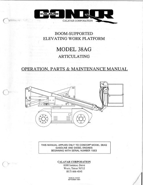
BOOM-SUPPORTEDELEVATING WORK PLATFORMMODEL <strong>38AG</strong>ARTICULATINGOPERATION, PARTS & MAINTENANCE MANUALTHIS MANUAL APPLIES ONLY TO CONDOR® MODEL <strong>38AG</strong>GASOLINE AND DIESEL ENGINESBEGINNING WITH SERIAL NUMBER 1563CALAVAR CORPORATION8300 IMPERIAL DRIVEWACO, TEXAS 76712(817) 666-4545MANUAL 92323SEPTEMBER 1994
INTRODUCTION•The primary purpose of this manual is to provide the user with a thorough understandingof the proper operating procedures necessary to comply with the intended useof the CONDOR®, and to provide the information necessary to maintain and service theCONDOR®.THE OPERATOR'S MANUAL MUST BE RETAINED ON THE UNIT AT ALL TIMES.Do not attempt to operate or service the CONDOR® until you have readand understood all information provided in this manual. Familiarize yourselfwith the functions and operations of the upper and lower controls. Agood understanding of the controls, their limitations, and their capabilitieswill maximize operating efficiency and safety. The various decals attachedto this machine also contain vital safety and operational instructions.Read the decals before operating this machine.It is YOUR RESPONIBILITY to follow safe procedures while operating the CONDOR®.The manufacturer of this unit cannot control the wide range of applications that may beused in carrying out a variety of jobs. Therefore, it is THE USER'S RESPONSIBILITY toconsider the safety of all personnel when making decisions regarding the unit's intendeduse.It is also YOUR RESPONSIBILITY to understand and obey all federal, ai id localregulations regarding the safe operation and use of aerial work platforms. A copy ofthe ANSI/SIA 92.5-1992 Manual of Responsibilities is attached for your useCalavar Corporation reserves the right to modify, improve, add, and/or delete certaindesign features of its products without any obligation to incorporate new features intoproducts previously sold. Our manuals are continually updated to reflect thesechanges.DO NOT ALTER OR MODIFY THIS UNIT WITHOUT PRIOR WRITTEN APPROVALFROM THE MANAGEMENT OF CALA VAR CORPOR4770N•.•SERVICE & MAINTENANCE••Many of the parts used in the manufacture of the CONDOR® have specific properties,and the manufacturer recommends that replacement parts be purchased through CalavarCorporation in order to ensure the original integrity of the fieoduct. Repairs andadjustments should only be made by trained and qualified personne:. 'lease refer to themaintenance and parts sections of the Calavar Operation, Maintenance, & Parts Manualfor information on service and maintenance of the CONDOR®.NOTE:Please refer to the Calavar Parts section of the Operation, Maritenance, &Parts Manual for information pertaining to your machine.MANUAL 92323SEPTEMBER 1994
CALAVAR CORPORATIONBOOM-SUPPORTEDELEVATING WORK PLATFORMMODELS <strong>38AG</strong>, 47AG, AND 47AEARTICULATINGOPERATOR'S MANUALCALAVAR CORPORATION8300 IMPERIAL DRIVEWACO, TEXAS 76712(817) 666-4545MANUAL 92265-001SEPTEMBER 1994
INTRODUCTIONThe primary purpose of this manual is to provide the user with a thorough understandingof the proper operating procedures necessary to comply with the intended useof the CONDOR®, and to provide the information necessary to maintain and service theCONDOR®.THE OPERATOR'S MANUAL MUST BE RETAINED ON THE UNIT AT ALL TIMES.Do not attempt to operate or service the CONDOR® until you have readand understood all information provided in this manual. Familiarize yourselfwith the functions and operations of the upper and lower controls. Agood understanding of the controls, their limitations, and their capabilitieswill maximize operating efficiency and safety. The various decals attachedto this machine also contain vital safety and operational instructions.Read the decals before operating this machine.It is YOUR RESPONIBILITY to follow safe procedures while operating the CONDOR®.The manufacturer of this unit cannot control the wide range of applications that may beused in carrying out a variety of jobs. Therefore, it is THE USER'S RESPONSIBILITY toconsider the safety of all personnel when making decisions regarding the unit's intendeduse.It is also YOUR RESPONSIBILITY to understand and obey all federal, state, and localregulations regarding the safe operation and use of aerial work platforms. A copy ofthe ANSI/SIA 92.5-1992 Manual of Responsibilities is attached for your use.Calavar Corporation reserves the right to modify, improve, add, and/or delete certaindesign features of its products without any obligation to incorporate new features intoproducts previously sold. Our manuals are continually updated to reflect thesechanges.DO NOT ALTER OR MODIFY THIS UNIT WITHOUT PRIOR WRITTEN APPROVALFROM THE MANAGEMENT OF CALA VAR CORPORATIONSERVICE & MAINTENANCEMany of the parts used in the manufacture of the CONDOR® have specific properties,and the manufacturer recommends that replacement parts be purchased through CalavarCorporation in order to ensure the original integrity of the product. Repairs andadjustments should only be made by trained and qualified personnel. Please refer to themaintenance and parts sections of the Calavar Operation, Maintenance, & Parts Manualfor information on service and maintenance of the CONDOR®.NOTE:Please refer to the Calavar Parts section of the Operation, Maintenance, &Parts Manual for information pertaining to your machine.MANUAL 92265-001SEPTEMBER 1994
TABLE OF CONTENTSINTRODUCTIONTABLE OF CONTENTSiiI. PREPARATION, INSPECTION, AND MAINTENANCE 1A. Overall Machine Condition 1B. Lower Control Station 1C. Platform and Upper Control Station 2D. Hydraulic System 2E. Multi-Axis Slope Sensor 2F. Batteries/Charger 2II. MACHINE OPERATION 2A. Rated Work Load 2B. Upper Controls, Gas & Diesel Power 3C. Lower Controls, Gas & Diesel Power 3D. Upper Controls, Electric Power 5E. Lower Controls, Electric Power 5F. Travel 7III. OPTIONAL EQUIPMENT 7IV. AUXILIARY LOWERING 7V. MOVING FROM JOB SITE TO JOB SITE 8A. TOWING 8B. TRANSPORTING 8VI. EMERGENCY STOPPING 8APPENDIX: DECALS ILLUSTRATION 9INSPECTION REPORTANSI/SIA 92.5-1992 MANUAL OF RESPONSIBILITIESMANUAL 92265-001SEPTEMBER 1994
IMPORTANT: A COPY OF THE ANSI/SIA 92.5-1992 MANUAL OF RESPONSIBILITIES ISATTACHED TO THIS OPERATOR'S MANUAL. IT CONTAINS IMPORTANT OPERATINGINFORMATION FOR THIS MACHINE. READ BEFORE OPERATING THIS MACHINE.I. PREPARATION, INSPECTION, STEERING:AND MAINTENANCECheck tie rod ends and steeringElThe condition of this unit is very impor-cylinder for proper and securetant, as it directly affects the operator'smounting.safety as well as the safety of others.The operator must perform a thoroughwalk-around inspection each day prior toSWING BEARING:operating the machine. Any damage orfaulty operation should be reported immediately.A DO NOT OPERATE tag outlin-securely in place.Check that all mounting bolts areing the problem should be attached to thelower control station and any discrepanciesshould be corrected before operatingDECALS:the CONDOR®.Check that all decals and warningKNOW THE UNIT AND ITS CAPABILITIES. signs are in place and are clearlyREPORT ANY UNUSUAL OPERATION,legible.SUCH AS ERRATIC SWAY OR MOTIONOF THE BOOM, ARM, OR PLATFORM.Some major areas to check daily are:A. OVERALL MACHINE CONDITIONTIRES AND WHEELS:Check for proper tire pressure,cracks, tears, cuts, or missing orloose lug nuts (a rust line runningdown the rim from the lug nutindicates a loose lug nut).CAUTION:Defective components,structural damage, missingparts, and equipment malfunctionjeopardize thesafety of the operator andother personnel and maycause excessive damage tothe unit. A poorly maintainedmachine could becomethe greatest operationalhazard you mayencounter.MISSING, BROKEN, OR DAMAGED B. LOWER CONTROL STATIONPARTS:Check cylinder mounting pins,pivot pins, retainers/fasteners,bearing pads, bolts, and nuts.STRUCTURAL:Check for damaged or crackedwelds on structural components--boom, arm, platform, skirt, chassis,and turret.Check electrical installations forloose, broken, or frayed wires andcables.Check that all functions operateproperly, and that all controlsreturn freely to center (neutral).1MANUAL 92265-001SEPTEMBER 1994
C. PLATFORM AND UPPER The slope sensor is located adjacent toCONTROL STATIONthe lower controls (see illustration).Check electrical installations forloose, broken, or frayed wires andcables. Re-check the structuralcondition of the platform, pivotpoints, pins, railings, and floor.EiCheck the general condition of theslope sensor, inspect for loose ordamaged wires, and ensure thatmounting is secure and that housingis not cracked or broken.LIIElCheck to see that slide bar is inplace and moves freely at accessopening. See that footswitchoperates properly, and that guardis secured and in its proper placeon the platform floor.Check the red EMERGENCY STOPbutton; this button disconnectspower to the controls and stops allpowered functions.Check the operation of the auxiliarylowering pump.F. BATTERIES/CHARGERLILICheck electrolyte level and ensurethat all caps are present andinstalled properly. Cable connectionsshould be tight and clean.(Electric models) Ensure thatcharger is operating properly, andinspect charger, plug, and meterfor damage.G. MOTORS/ENGINED. HYDRAULIC SYSTEMEl Check the hydraulic tank fluid levelwith the arms lowered and theboom lowered and retracted.Maintain fluid level at the full markon the sight glass. Add only ShellTellus T-32 Hydraulic Oil (orequivalent) to the system. Ensurethat the breather cap is clean andin place on the tank.LILICheck for hydraulic oil leaks at allfittings, valves, and controls, andcheck hydraulic hoses and tubesfor damage and kinks.Ensure that hydraulic lines arerouted properly to avoid pinchpoints.E. MULTI -AXIS SLOPE SENSORThe CONDOR® is equipped with a slopesensor to warn the operator of an out-ofleveloperating condition.LILICheck to see that power units areoperating properly. Inspect forloose cables or fasteners.(Gas/diesel models) Check all fluidlevels—oil, fuel, and coolant.Inspect air cleaner and muffleroperation and mounting, andperform routine maintenance asrecommended in engine manual.II. MACHINE OPERATIONA. RATED WORK LOADThe CONDOR® Models 38A and 47A havean rated work load of 500 lbs. (226.8 kg),or two occupants. This means that theplatform will support a 500-1b. combinedweight (including personnel and their toolsand equipment) throughout the workingenvelope of the machine.MANUAL 92265-001SEPTEMBER 19942
Models <strong>38AG</strong>, 47AG —Gas & Diesel PowerUPPER CONTROLSDRIVE/STEEREMERGENCY STOPBOOM LIFTENGINE STARTLP/GAS (OPTION)CHOKE/GLOWPLUGSDRIVE SPEED SELECTORAUX. LOWERING(OPTION)TURRET ROTATEPLATFORM TILTBOOM EXTENDARM LIFTLOWER CONTROLSENGINE STARTEMERGENCY STOPCHOKE/GLOWPLUGSAUX. LOWERING (OPTION)THROTTLEKEY SWITCH& UPPER/LOWERCONTROL STATIONSELECTORARM LIFTBOOM EXTENDTURRET ROTATEBOOM LIFT3MANUAL 92265-001SEPTEMBER 1994
B. UPPER CONTROLS, GAS &DIESEL POWERThe upper control station provides forcomplete operation of the machine. As asafety precaution, the footswitchmounted on the platform floor must bedepressed and held during all functions.The upper control console is equippedwith a red EMERGENCY STOP switch thatwill cease all movement and (on gas anddiesel models) stop the engine.On engine-powered units, the uppercontrol console will contain an engineSTART switch and either a CHOKE (gasengines) or GLOWPLUGS switch (dieselengines). If the CONDOR® is equippedwith an optional dual fuel system, theconsole will also contain an LP/GASswitch for selecting the mode of fuelconsumption.The upper control console also contains adrive speed selector switch, which allowsthe operator to select either FAST orSLOW speed, and a DRIVE/STEER controller.The steering control is a spring-loaded,return-to-center rocker switch located on topof the drive control handle. With the counterweightover the steer wheels, the steeringcontrol moves the unit in the direction inwhich the rocker switch is actuated.Directly in front of the control console arefive (5) handles that control the followingfunctions: ARM LIFT, BOOM EXTEND,PLATFORM TILT, TURRET ROTATION,and BOOM LIFT. The aerial functionscorrespond directly to the movement ofthe control levers in the directions indicatedon the control valve decal.When set properly, the platform on Models38A and 47A will remain levelthroughout the operational envelope ofthe machine.The CONDOR® is also equipped with ahand-operated rotating platform. Torotate the platform, turn the handlelocated on the right side of the skirt, justbelow the control station.C. LOWER CONTROLS, GAS &DIESEL POWERThe lower control station is located on theturret of the machine. The DRIVE/STEERfunctions are not operable from the lowercontrols; all other functions may beoperated from the lower control station.The main key switch is located on thelower control console. With the key inthe center (OFF) position, power is disengaged.With the key in the left (LOWER)position, the lower controls are energizedfor operation. With the key in the right(UPPER) position, the upper controls areenergized for operation.The THROTTLE switch must be depressedcontinuously in order to operate thefunctions from the lower control station.On engine-powered units, the controlconsole contains an engine START switchand either a CHOKE (gas engines) orGLOWPLUGS (diesel engines) switch toassist in starting the engine.Also located on the lower control consoleis the optional auxiliary lowering switch.This switch is used to energize the auxiliarypump and motor, which may be usedto lower the platform in the case ofprimary power failure.Adjacent to the lower control console arefour (4) handles that control the followingfunctions: ARM LIFT, BOOM EXTEND,TURRET ROTATION, and BOOM LIFT.The lift functions correspond directly tothe movement of the control levers in thedirections indicated on the control valvedecal.NOTE: The CONDOR® is not equippedwith continuous turret rotation. With thecounterweight over the drive wheels, theturret may be rotated 179° in eitherdirection until the stop is reached.MANUAL 92265-001SEPTEMBER 19944
Model 47AE —Electric PowerUPPER CONTROLSDRIVE/STEERPOWER ON/OFFBATTERYCONDITIONINDICATORDRIVE SPEEDSELECTORTURRET ROTATEBOOM LIFTBOOM EXTENDPLATFORM TILTARM LIFTLOWER CONTROLSPUMPKEY SWITCH& UPPER/LOWERCONTROL STATIONSELECTORHOUR METERARM LIFTBOOM EXTENDTURRET ROTATEBOOM LIFT5MANUAL 92265-001SEPTEMBER 1994
B. UPPER CONTROLS,ELECTRIC POWERThe upper control station provides forcomplete operation of the machine. As asafety precaution, the footswitchmounted on the platform floor must bedepressed and held during all functions.The upper control console is equippedwith a red POWER switch that will ceaseall movement and disengage the powerunit.The upper control console contains adrive SPEED selector switch, whichallows the operator to select either FASTor SLOW speed, and a DRIVE/STEERcontroller. The steering control is a springloaded,return-to-center rocker switchlocated on top of the drive control handle.With the counterweight over the steerwheels, the steering control moves the unitin the direction in which the rocker switch isactuated.The console also contains five (5) handlesthat control the following functions: ARMLIFT, BOOM EXTEND, PLATFORM TILT,TURRET ROTATION, and BOOM LIFT.The aerial functions correspond directly tothe movement of the control handles; thedirection of operation for each function isindicated on the upper control consoledecal.When set properly, the platform on Models38A and 47A will remain levelthroughout the operational envelope ofthe machine.The CONDOR® is also equipped with ahand-operated rotating platform. Torotate the platform, turn the handlelocated on the right side of the skirt, justbelow the control station.Electric models may be equipped with anoptional battery condition indicator at theupper control station.C. LOWER CONTROLS,ELECTRIC POWERThe lower control station is located on theturret of the machine. The DRIVE/STEERfunctions are not operable from the lowercontrols; all other functions may beoperated from the lower control station.The key switch is located on the lowercontrol console. With the key in thecenter (OFF) position, power is disengaged.With the key in the left(GROUND) position, the lower controlsare energized for operation. With the keyin the right (PLATFORM) position, theupper controls are energized for operation.The PUMP switch must be depressedcontinuously in order to operate thefunctions from the lower control station.Also located on the lower control consoleis the optional auxiliary lowering switch.This switch is used to energize the optionalauxiliary pump and motor, whichmay be used to lower the platform in thecase of primary power failure.The lower control console contains four(4) handles that control the followingfunctions: ARM LIFT, BOOM EXTEND,TURRET ROTATION, and BOOM LIFT.The lift functions correspond directly tothe movement of the control handles inthe directions indicated on the controlconsole.All models are equipped with an hourmeter at the lower control station.NOTE: The CONDOR® is not equippedwith continuous turret rotation. With thecounterweight over the drive wheels, theturret may be rotated 179° in eitherdirection until the stop is reached.MANUAL 92265-001SEPTEMBER 19946
D. TRAVELDriving the machine may only be accomplishedfrom the upper control station,with the boom in raised or lowered(stowed) position. Even thought thegradeability of the unit is 14° (25%),such a grade should only be negotiatedwith the boom in the fully lowered(stowed) position and in SLOW drivespeed. The CONDOR® is designed totravel with the platform elevated onlywhen on firm, level ground.The CONDOR® is designed to be drivenwith the counterweight positioned overthe drive wheels. In this configuration,the direction of travel corresponds directlyto the direction of movement of the drivecontroller. Moving the controller awayfrom the operator drives the unit forward;moving the controller toward the operatormoves the unit in reverse.The steering control is a spring-loadedreturn-to-center rocker switch located ontop of the drive controller handle. Withthe counterweight over the drive wheels,the steering direction corresponds directlyto the direction in which the rockerswitch is activated. Pushing the rockerswitch to the left turns the unit to theleft, and pushing the rocker switch to theright moves the unit to the right. Whenthe rocker switch is released and returnsto center, the sterring wheels remain inthe last directed line of travel and do notreturn to a straight line of travel; steeringis not self-centering.When the machine is driven with thecounterweight in a position other than asdescribed above, the relationship of thedrive and steer functions to the movementof the controller will change. Theoperator should move the unit slowly untilfamiliar with this change in movement.Always look in the direction of travel andmaintain a clear field of view, payingparticular attention to overhead obstructions.Avoid erratic movement of the controllerby moving smoothly into and out oftravel. Come to a complete stop beforechanging directions.The brakes on the unit are spring-appliedand hydraulically released. The brakesare automatically released when the drivecontroller is returned to the neutral position.The upper control console is equippedwith a maintained two-position toggleswitch to select either FAST or SLOWtravel speed. However, when the boomor arms are raised sufficiently to open theboom limit switch (approximately horizontal),both drive speeds are automaticallyreduced by one half.III. OPTIONAL EQUIPMENTThe following options are available on theCONDOR® Models 38A and 47A:• 110-Volt Line to Platform• Foam-Filled Tires• Motion/Travel Warning Horn• Low Voltage Warning (electric models)• Strobe Light/Rotating Beacon• Larger Platform• Air Line to Platform• Platform Work Lights• Diesel Engine• Dual Fuel (liquid, vapor)IV. AUXILIARY LOWERINGProvisions are made to return the operatorto the ground in the event of primarypower loss.The boom and arm lift cylinders on electricunits are equipped with (manual)gravity lowering cartridges on the holdingvalves. To lower the boom or arm manually,depress the red button and turncounter-clockwise. The lowering processmay be halted at any time by depressingthe red button and turning clockwise.7MANUAL 92265-001SEPTEMBER 1994
On electric models, the turret may berotated manually by placing the ROTA-TION TOOL provided (located directlybelow the rotation gearbox) over the hexhead shaft of the rotation gearbox.Optional on engine-powered units is anauxiliary power unit which is operatedfrom both control stations. This optionallows the lift functions to be operated incase of engine or main pump failure.Push and hold the AUXILIARY LOWERINGswitch while operating the desired function.V. MOVING FROM JOB SITETO JOB SITEA. TOWINGThe brakes on the CONDOR® are automaticallyapplied when the drive controlleris returned to neutral. However, fortowing purposes the drive hubs may bedisengaged by removing the two (2) bolts(.25" - 20UNC x .75" long) that securethe disconnect cap, removing the disconnectcap and reinstalling with the nipplefacing inward, and resecuring the capusing the two bolts.making sure that the controls return tocenter smoothly when released. Movethe CONDOR® slowly back and forth toensure that the brakes apply each timethe drive controller is released.It may be necessary to elevate the boomor lift the arms to clear the ramp duringloading. The unit is equipped with a slopesensor that will warn the operator of anout-of-level condition of 5° or greater.Move the unit up or down the rampslowly, allowing time for steering correctionsto be made, and keep the unit inalignment with the ramp and carrierduring loading and unloading operations.The . CONDOR® may be transported easilyand safely to and from the work site bycompleting the following procedures:block all wheels to prevent forward andreverse movement during transportation;tie down the CONDOR® using chains,straps, or cables of sufficient strength;set the platform on wooden pallets and tiethe boom down near the skirt; turn off thepower at the key switch and remove thekey. [See diagram below]FACTORY RECOMMENDED• TRANSPORTATION DIAGRAMB. TRANSPORTINGThe CONDOR® Model 47A weighs approximately12,500 lbs.; Model 38Aweighs approximately 11,500 lbs. Themeans of loading or unloading must be ofsufficient strength to withstand theweight of these machines.When using a ramp, it should be set at anangle no greater than 14° or 25% (30"rise in 10 feet).Remember that the normal driving positionof the CONDOR® is with the counterweightover the drive wheels, and thatany other position will change the operationof the drive and steer functions.Before driving the unit onto the ramp, testeach of the controls and the brakes,[Decal located on chassis—both sides]VI. EMERGENCY STOPPINGAs stated previously, the EMERGENCYSTOP button may be used in an emergencyto stop movement from both theupper and lower control stations. However,the foot may be taken off of thefootswitch to 'panic stop' any function,including drive and steer.MANUAL 92265-001SEPTEMBER 19948
APPENDIX: DECALS ILLUSTRATION[Model 47AG Shown]21151917110.MAINIJICIRI0 035269MANUAL 92265-001SEPTEMBER 1994
APPENDIX: DECALS ILLUSTRATION47AG 47AD 47A <strong>38AG</strong> 38ADITEM PART NUMBER DESCRIPTION QTY QTY QTY QTY QTY1 34271 Decal, 47A 2 2 2 N/A N/A37290 Decal, 38A N/A N/A N/A 2 22 50172 Decal, CONDOR® 2 2 2 2 23 35366 Decal, Gen. Op. Instructions 1 1 1 1 14 21882-001 Decal, Electrocution Hazard 2 2 2 2 25 21882-002 Decal, This Unit Not Insulated 2 2 2 2 26 21882-003 Decal, Danger: Qual. Operator 1 1 2 1 17 52759 Decal, Stand Clear/Operating 2 2 2 2 28 37348 Decal, Lower Valves (see NOTE 1) 1 1 1 1 19 34270 Decal, Upper Valves 1 1 1 1 110 21850 Decal, Hydraulic Fluid 1 1 2 2 211 50070 Decal, Battery Service 1 1 2 1 112 37354 Decal, Aux. Lwrg. (see NOTE 2) 1 1 N/A 1 167880 Decal, Emergency Lowering (47A) N/A N/A 1 N/A N/A13 35042 Decal, Forward (Arrow) 1 1 1 1 114 35043 Decal, Forward 1 1 1 1 115 67938-100 Decal, Tire Press. 100 PSI (47AG) 4 4 N/A N/A N/A34523 Decal, Tire Pr. 60 PSI (<strong>38AG</strong>/47A) N/A N/A 4 4 416 21849 Decal, Gas 1 N/A N/A 1 N/A15376-012 Decal, Diesel 1 1 N/A N/A 117 21971-002 Decal, Do Not Lift Wheels w/Boom 2 2 2 2 218 37784 Decal, Transportation Diagram 2 2 2 2 219 35656 Decal, Made in U S A —6 00" 1 1 1 1 120 68859 Decal, Oil Dipstick Inside 1 1 N/A 1 121 81417 Decal, Rated Work Load 1 1 1 1 122 36885 Decal, 500 LBS 1 1 1 1 123 54416 Decal, Caution: Tie-Down Ring 3 3 3 3 324 37419 Decal, Panic Stop/Ramping Control 1 1 1 1 125 58419 Tape, Orange/Red 5.00" (linear ft.) 39 39 39 39 3926 38176 Decal, Manual Lowering Procedure 2 2 N/A 2 227 32200 Decal, Warning Power Lines 1 1 1 1 128 37958-500 Decal, Rated Work Load 500 LBS 1 1 1 1 129 Nameplate, Booms Identification 1 1 1 1 130 38072 Decal, Lower Control Console 1 N/A N/A 1 N/A37365 Decal, Lower Control Console N/A 1 N/A N/A 137024 Decal, Pump (electric models) 1 N/A 1 N/A N/A31 37969 Decal, Key Switch—Upper/Lower 1 1 N/A 1 137025 Decal, Key Switch—Ground/Plat. N/A N/A 1 N/A N/A32 38144 Decal, Upper Control Console 1 1 N/A 1 137080 Decal, Upper Control Console N/A N/A 1 N/A N/A33 67812 Decal, Glowplugs (diesel models) N/A 2 N/A N/A 234 52735 Decal, 110 Volts option .. option ...option .. option . option35 15376-024 Decal, 110V Power To Platform option .. option ...option .. option . option36 67881 Decal, Rotation Tool Inside 1 1 1 1 137 34767 Decal, Aux. Lowering (plat. cntrl.) .... option .. option ...option .. option . option(see NOTE 2)- Indicates Items Not ShownNOTE: 1. Decal #37348, showing lower control valve operation, replaces decal #34502.2. Decal #34767 is used to indicate the pushbutton control for Auxiliary Lowering on unitsequipped with an optional auxiliary power unit. Decal #37354 contains the instructionsfor auxiliary lowering on units equipped with the optional power unit.MANUAL 92265-001SEPTEMBER 199410
NOTESMANUAL 92265-001SEPTEMBER 1994
CA la R.VA RCALAVAR CORPORATIONCondor® Self-Propelled Aerial Work PlatformsWARRANTYCalavar Corporation ("Calavar") warrants to the purchaser that each new aerial work platformmade by Calavar is free from defects in material and workmanship arising under normal useand service—in the case of major weldments, (chassis, turret, and booms), for a period of five(5) years after the original shipment of the aerial work platform from Calavar's plant; and inthe case of all other parts, for a period of one (1 ) year after the aerial work platform is placedin service or two (2) years after the original shipment of the aerial work platform from Calavar'splant, whichever comes first.The obligation and liability under this Warranty is expressly limited to repairing or, at Calavar'soption, replacing free of charge at its factory or at an authorized repair facility designated byCalavar, the defective part. In no event shall Calavar or its suppliers be liable to the purchaseror any other person for transportation charges or for any incidental, collateral, special, orconsequential damages, including without limitation damages for loss of profits, loss ofcustomers, loss of goodwill or work stoppage, claims by any party other than the purchaser,or any other similar damage or loss even if Calavar, its suppliers, or its representatives havebeen advised of the possibility of such damages.Parts claimed to be defective and for which repair or replacement is desired shall be returnedtransportation prepaid to Calavar's factory for inspection. This Warranty applies toreplacement parts provided under the terms of this Warranty only for the remainder of theWarranty period applicable to the original purchase.Any operation of the equipment beyond rated capacity, improper use or application of theequipment, substitution upon it of parts not approved by Calavar or alteration or repair of theequipment by any person not authorized by Calavar shall, at Calavar's option, void thisWarranty. Calavar shall have no liability or responsibility for damages resulting from accidentor the malfunction of equipment and components not supplied by Calavar.No agent, employee, distributor, dealer, or other representative of Calavar is authorized tomodify this Warranty in any way. Accordingly, additional statements or presentations by anysuch representative, whether oral or written, do not constitute warranties by Calavar andshould not be relied upon as limited warranties of Calavar, and no attempt, effort, or promiseto repair equipment by Calavar or any such representative at any time shall modify or extendthis Warranty in any way. If the purchaser has used its own order form, no additional ordifferent warranty terms contained in the purchaser's form will be honored by Calavar. ThisWarranty covers only new and unused aerial work platforms manufactured by Calavar.Products or parts manufactured by others are covered only by such warranties as are extendedto the purchaser by Calavar's suppliers.This Warranty is in lieu of all other warranties, expressed or implied, including but not limitedto warranties of merchantibility and fitness for a particular purpose. Any applicable impliedwarranty shall be limited in duration to the warranty period.8300 Imperial Drive, P.O. Box 21447, Waco, Texas 76702-1447817-666-4545, FAX 817-666-4544Printed in U.S.A.MANUAL 92265-001SEPTEMBER 1994
NOTESMANUAL 92265-001SEPTEMBER 1994
CALAVAR CORPORATIONBOOM-SUPPORTEDELEVATING WORK PLATFORMMODEL <strong>38AG</strong>ARTICULATINGMAINTENANCE MANUALTHIS MANUAL APPLIES ONLY TO CONDOR® MODEL <strong>38AG</strong>GASOLINE AND DIESEL ENGINESBEGINNING WITH SERIAL NUMBER 1563CALAVAR CORPORATION8300 IMPERIAL DRIVEWACO, TEXAS 76712(817) 666-4545MANUAL 92323-002SEPTEMBER 1994
INTRODUCTIONThe primary purpose of this manual is to provide the user with a thorough understandingof the proper operating procedures necessary to comply with the intended useof the CONDOR®, and to provide the information necessary to maintain and service theCONDOR®.THE OPERATOR'S MANUAL MUST BE RETAINED ON THE UNIT AT ALL TIMES.Do not attempt to operate or service the CONDOR® until you have read and understoodall information provided in this manual. Familiarize yourself with the functions andoperations of the upper and lower controls. A good understanding of the controls, theirlimitations, and their capabilities will maximize operating efficiency and safety. Thevarious decals attached to this machine also contain vital safety and operational instructions.Read the decals before operating this machine. The parts and maintenancesections of this manual will serve as a tool to be used in servicing the machine and inordering parts. When referring to this manual, please note the publication date and anySerial Number information pertaining to this manual and its corresponding model(s).It is YOUR RESPONIBILITY to follow safe procedures while operating the CONDOR®.The manufacturer of this unit cannot control the wide range of applications that may beused in carrying out a variety of jobs. Therefore, it is YOUR RESPONSIBILITY to considerthe safety of all personnel when making decisions regarding the unit's intendeduse. It is also YOUR RESPONSIBILITY to understand and obey all federal, state, andlocal regulations regarding the safe operation and use of aerial work platforms. TheANSI/SIA Manual of Responsibilities pertaining to this model is attached for your use.Calavar Corporation reserves the right to modify, improve, add, and/or delete certaindesign features of its products without any obligation to incorporate new features intoproducts previously sold. Our manuals are continually updated to reflect thesechanges.DO NOT ALTER OR MODIFY THIS UNIT WITHOUT PRIOR WRITTEN APPROVALFROM THE MANAGEMENT OF CALA VAR CORPORATIONSERVICE & MAINTENANCEMany of the parts used in the manufacture of the CONDOR® have specific properties,and the manufacturer recommends that replacement parts be purchased through CalavarCorporation in order to ensure the original integrity of the product. Repairs andadjustments should only be made by trained and qualified personnel. Please refer to themaintenance and parts sections of the Calavar Operation, Maintenance, & Parts Manualfor information on service and maintenance of the CONDOR®.NOTE:Please refer to the Calavar Parts section of the Operation, Maintenance, &Parts Manal for information pertaining to optional parts.MANUAL 92323-002SEPTEMBER 1994
CONDOR® MODEL <strong>38AG</strong>BEGINNING WITH SERIAL NUMBER 1563MAINTENANCE MANUALTABLE OF CONTENTSCONDOR® SERVICE INFORMATIONCHECK-OUT INSTRUCTION 1WARRANTY PROGRAM 3A. WARRANTY PERIOD 5B. PRE-DELIVERY INSPECTION SHEET (P.D.I.) 6C. ITEMS NOT COVERED 6D. PROCESSING OF CLAIM 7E. RETURN AUTHORIZATION 7SERIAL NUMBER LOCATION 9MANUAL 92323-002SEPTEMBER 1994
CA IL. INVII 14CALAVAR CORPORATIONCONDOR® SERVICE INFORMATION1. If you need assistance or have any service or maintenance questions, Calavar serviceand parts personnel are always available by phone or fax. The telephone numbers are:(817) 666-4545 Telephone(817) 666-5125 Voice Mail(800) 443-5803 FAX2. There are numerous written Maintenance Procedures available for this machine. Theseprocedures are available through the Calavar Service Department to anyone whorequests them.3. Service and maintenance are not a substitute for trained, qualified service technicians.Calavar conducts service schools on a continuing basis. Call any of our service or salespersons for a schedule. Remember, training of mechanics is the responsibility of theiremployer, but Calavar Service Schools help you provide this training.4. Calavar Service School Training Manuals are available for purchase through the partsdepartment. The part numbers for these manuals are: #92333 for self-propelled models;and #92334 for truck-mounted models.CALAVAR CORPORATION8300 IMPERIAL DRIVE, P.O. Box 21447, WACO, TEXAS 76702-1447 • 817-666-4545, 817-666-4544 FAXMANUAL 92323-002SEPTEMBER 1994
CHECK-OUT INSTRUCTIONThe following instructions are a step-by step procedure for checking out the selfpropelledCONDOR®, as well as for acquainting operating personnel with the unit'soperation. This procedure will not take more than one hour and is time well-spent,as it will give both operating and maintenance personnel preliminary experience anda better understanding of the operation of the self-propelled CONDOR®.Prior to placing the unit into service, a full check-out of the unit should be made andthe Installation Inspection Report should be completed and returned to Calavar.Each unit has undergone a thorough Quality Control Inspection, and each unit leavesCalavar in first-class condition. Unfortunately, some units may be damaged intransportation; all such damage should be recorded on the consignee copy of thefreight bill. Calaver Corporation is not responsible for damage to units in transit.1. Visually inspect all exposed components. Check for loose nuts and bolts,damaged hydraulic lines, broken wires, and structural damage.2. IMPORTANT: Check tire pressure. Tires must be properly inflated beforeoperating the unit. Do not over-inflate. Proper P.S.I. rating appears ondecals applied to both sides of the carriage.3. Check hydraulic oil level and add Shell Tellus T-32 hydraulic oil, if required.4. Fill fuel tank using unleaded gasoline or diesel fuel.5. Check battery with an hydrometer. Battery must have a full charge.6. Inspect all hydraulic valves located in the front carriage compartment beforeputting the unit into service.7. Turn on the key switch at the lower control station; IF D1ESEL-POWERED,first activate glowplugs and allow 30 seconds before starting engine. Depressthe start button and allow engine to warm up at idle. After the unithas warmed up, and with the UPPER/LOWER control station selector switchin the LOWER position, the unit may be operated by activating the controlhandles on the lower control valve. While wheel drive is not available fromthe lower control station, the engine may be started and stopped from bothcontrol stations.8. With the key switch ON, switch to the UPPER control station. Position theunit in an area that is free from any overhead obstruction. At the uppercontrol station, engage the footswitch and activate a control lever whilemaintaining pressure on the footswitch. Ensure that when released, thecontrol levers return to center. Learn to operate the controller slowly toobtain the smoothest possible operation.MANUAL 92323-002SEPTEMBER 19941
9. The CONDOR® has been designed to drive with the counterweight over thedrive wheels. This configuration will provide the best traction and a familiardriving position.10. A series/parallel drive valve is located in the front carriage compartmentbetween the drive wheels. This valve performs the necessary functions ofdividing the hydraulic oil for slow speed travel with adjustable differentialaction to round corners, and diverting the oil flow for high speed travel. Thecounterbalance valve softens the brake release and application efficientlywithout an accumulator.1 1 . The wheel drive has the following features:A. There is a FAST/SLOW speed selector (toggle switch) on the uppercontrol box.B. FAST speed is only available in stowed position.C. In FAST speed mode, no aerial functions may be operated, even if thecontrollers are activated. When the boom is elevated off of the turret,HIGH speed is not available and boom functions become operable.D. A CREEP speed mode is automatically engaged when the lift arm israised or the boom is elevated out of its stowed position.1 2. Operate the boom at a horizontal position until you are familiar with theoperation and feel of the controls. The unit will respond more smoothly tothe controls when they are activated properly.1 2. Gradually operate the unit up to its maximum elevation and extension.13. All CONDOR® models are equipped with a slope-sensing device which sensesa 5° out-of-level condition. This safety system is operational when theignition circuit is on and the boom is above horizontal. When the unit issubjected to an out-of-plumb condition of 5° or more, the system will soundan audible alarm at both control stations. The operator should correct thecondition by reversing the drive direction or by selecting an alternate path,observing normal safety precautions when operating the equipment. Theslope-sensing device is a safety system and must not be disconnected.Should the system be found inoperable, the unit must be taken out of serviceand must not be used until the system has been repaired.2MANUAL 92323-002SEPTEMBER 1994
CA EWA 14CALAVAR CORPORATIONCondor® Self-Propelled Aerial Work PlatformsWARRANTYCalavar Corporation ("Calavar") warrants to the purchaser that each new aerial work platformmade by Calavar is free from defects in material and workmanship arising under normal useand service—in the case of major weldments, (chassis, turret, and booms), for a period of five(5) years after the original shipment of the aerial work platform from Calavar's plant; and inthe case of all other parts, for a period of one (1) year after the aerial work platform is placedin service or two (2) years after the original shipment of the aerial work platform from Calavar'splant, whichever comes first.The obligation and liability under this Warranty is expressly limited to repairing or, at Calavar'soption, replacing free of charge at its factory or at an authorized repair facility designated byCalavar, the defective part. In no event shall Calavar or its suppliers be liable to the purchaseror any other person for transportation charges or for any incidental, collateral, special, orconsequential damages, including without limitation damages for loss of profits, loss ofcustomers, loss of goodwill or work stoppage, claims by any party other than the purchaser,or any other similar damage or loss even if Calavar, its suppliers, or its representatives havebeen advised of the possibility of such damages.Parts claimed to be defective and for which repair or replacement is desired shall be returnedtransportation prepaid to Calavar's factory for inspection. This Warranty applies toreplacement parts provided under the terms of this Warranty only for the remainder of theWarranty period applicable to the original purchase.Any operation of the equipment beyond rated capacity, improper use or application of theequipment, substitution upon it of parts not approved by Calavar or alteration or repair of theequipment by any person not authorized by Calavar shall, at Calavar's option, void thisWarranty. Calavar shall have no liability or responsibility for damages resulting from accidentor the malfunction of equipment and components not supplied by Calavar.No agent, employee, distributor, dealer, or other representative of Calavar is authorized tomodify this Warranty in any way. Accordingly, additional statements or presentations by anysuch representative, whether oral or written, do not constitute warranties by Calavar andshould not be relied upon as limited warranties of Calavar, and no attempt, effort, or promiseto repair equipment by Calavar or any such representative at any time shall modify or extendthis Warranty in any way. If the purchaser has used its own order form, no additional ordifferent warranty terms contained in the purchaser's form will be honored by Calavar. ThisWarranty covers only new and unused aerial work platforms manufactured by Calavar.Products or parts manufactured by others are covered only by such warranties as are extendedto the purchaser by Calavar's suppliers.This Warranty is in lieu of all other warranties, expressed or implied, including but not limitedto warranties of merchantibility and fitness for a particular purpose. Any applicable impliedwarranty shall be limited in duration to the warranty period.8300 Imperial Drive, P.O. Box 21447, Waco, Texas 76702-1447817-666-4545, FAX 817-666-4544Printed in U.S.A.MANUAL 92323-002SEPTEMBER 19943
NOTES4MANUAL 92323-002SEPTEMB ER 1994
Effective January 1, 1993WARRANTY PROGRAMWarranty is a function of a manufacturing company to back up the product it manufactures.It is a guarantee against defects in design and workmanship of components utilized in theproduct, and is offered for a fixed period of time following the purchase of the product bya customer.Calavar Warranty states, in general, that Calavar will replace free of charge anycomponents found to be defective within the time frame of the warranty period. There areexceptions to some components which are not the responsibility of Calavar. These will beoutlined in subsequent paragraphs.A. WARRANTY PERIOD1 . The Self-Propelled Boom and Scissor Warranty is one (1 ) year from placingthe unit in service or two (2) years following shipment from Calavar,whichever comes first. In the case of major weldments (chassis, turret, andbooms), the Warranty Period is five (5) years following shipment fromCalavar.2. The Truck-Mounted unit Warranty Period is one (1 ) year from shipment of theunit from Calavar's plant.3. For parts sold through the Parts Department, the Warranty Period is six (6)months from utilizing the component or placing it in service, or twelve (1 2)months following shipment from Calavar, whichever comes first, unless thepart is furnished to correct a defective part on the original shipment still underWarranty.4. Replacement parts provided under the terms of the Warranty are for theWarranty Period applicable to the unit in which they were installed as if suchparts were original components of the aerial work platform.5. During the Warranty Period, in addition to covering the parts replaced underWarranty, Calavar will pay a Dealer Warranty Labor Rate which is based ona percentage of your standard shop labor rate.NOTE:The term IN SERVICE" means that the Warranty starts at the time the unitis first used for any purpose. An example: The dealer may have purchaseda unit to have in stock, but may not use it. After three months, the unit issold or the dealer decides to put the unit into its rental fleet. In this situation,the Warranty Period begins the day the dealer puts the unit into the fleet orwhen the unit is delivered to the end user.The submittal of a warranty claim against a stock machine constitutes it asbeing "in service," initiating the warranty period.MANUAL 92323-002SEPTEMBER 19945
B. PRE-DELIVERY INSPECTION SHEET (P.D.I.)1 . Each Self-Propelled Boom or Scissor unit shipped from Calavar's facility willhave a Pre-Delivery Inspection (P.D.I.) sheet enclosed in the Safety Manualholder tube.2. It will be the responsibility of the original recipient of the unit from Calavar,whether it will be the dealer or the end user, to complete this form and returnit to Calavar's facility within 45 days from the date of receipt to set up theWarranty Account.3. Failure to complete the P.D.I. sheet and return it to Calavar within the timeframe given will result in voiding the Warranty on the unit.NOTE:The form must be filled out completely, giving the name of the dealer,address, model number, serial number, person inspecting the units, signature,and date of inspection. (The date of inspection does not constitute theIn Service" date.)C. ITEMS NOT COVEREDSome components are used on the machine which are not warranted by Calavar.However, these are warranted by the component manufacturer. Some of these are:1 . Engine: Manufacturers used include Wisconsin, Ford, Deutz, Isuzu, Kubota,Onan, Cummins, John Deere, and others. To apply for warranty on theengine, contact should be made with the engine manufacturer's dealer in yourarea. Calavar can advise you who the dealer is if unknown to you.2. Tires and Batteries: These are normal wear items and are considered normalmaintenance items. However, if they are found to be defective, contact canbe made with the manufacturer's local dealer.3. Hydraulic Filters and Fluid: These are considered general maintenance andservice items, and are not covered by warranty.4. Other components: Products or parts manufactured by others are coveredonly by such warranties as are extended to Calavar by its suppliers.5. Freight and Charges: The warranty does not include any transportation, othercharges, or the cost of installation or any liability for direct, indirect, orconsequential damages or delay resulting from the defect.6. Travel Time I Mileage: Travel time and the mileage to and from dealer facilitiesto machine location are not covered or reimbursable.7. Troubleshooting: Troubleshooting is not covered or reimbursable. However,Calavar Warranty will cover reasonable labor charges for the removal andreplacement of defective components.6MANUAL 92323-002SEPTEMBER 1994
D. PROCESSING OF CLAIMDuring the Warranty Period, should a component failure be encountered within theguidelines of the Calavar Warranty Policy, the following procedure is to be followed:1. Upon identifying the defective component, the replacement can be obtainedby:a. Issuing an order to our Parts Department through normal channels,which entails your being invoiced.b. You may have previously purchased the part from Calavar for yourstock and will utilize it for this replacement.The above two methods will enable you to indicate on the claim the Calavarinvoice number to substantiate the parts purchase and the amount to becredited.C. Although not recommended, you may purchase the part locally.When this is done, a copy of the purchase order or receipt MUSTaccompany the claim. Calavar has the option to ship a replacementpart at no charge if the local cost would be greater, in lieu of issingcredit for locally purchased parts.d. When parts are puchased from Calavar, part numbers with invoicenumbers MUST be referenced in the appropriate section of the claimform.2. Complete the Warranty Claim as noted in the "Warranty Claim Procedure"section. Provide as much information as possible to enable Calavar tothoroughly evaluate the claim and process it in the shortest amount of timepossible.NOTE:CLAIMS NOT RECEIVED BY CALAVAR WITHIN 45 DAYS OF FAILUREWILL BE DENIED3. Provided no return parts are required and all the information has been verified,the claim will be processed and credit will be issued against your account.E. RETURN AUTHORIZATION1 . If a component is found to be defective within the normal guidelines of theWarranty, a Warranty Claim Form must be completed.2. It will be necessary for you to call the Calavar Service Department and askto be issued a Return Authorization (R/A) number. You will be asked for aDealer Claim Number. As noted in Section 2, Item A, of the Warranty ClaimProcedure, this is a number assigned by the dealer for the purpose of trackingthe claim, as there may be more than one claim for the same unit. The R/Anumber issued must be logged in the appropriate section of the claim form,and the gold copy (R/A) of the form must be returned with the parts beingreturned.MANUAL 92323-002SEPTEMBER 19947
NOTE:DO NOT SHIP ANY RETURN PARTS WITHOUTA RETURN AUTHORIZATION (R/A) NUMBERDoing so may result in parts getting lost in the system and may delayprocessing the claim, or may cause denial dut to the time element of theclaim.3. All R/A parts must be received at Calavar within 45 days from the date theR/A number was issued. Failure to do so will cause the claim to be denied.4. All parts claimed under Warrranty will be required to be shipped back toCalavar FREIGHT PREPAID. No freight collect shipments will be accepted.8MANUAL 92323-002SEPTEMBER 1994
CONDOR® Model <strong>38AG</strong> Serial Number LocationSTAMP ON TURRET PLATESTAMP ON STEER AXLESTAMP ON DATA PLATEThe CONDOR® Model <strong>38AG</strong> Serial Number is stamped in three locations on the machine.1. The first place to find the serial number stamp is on the data plate affixed tothe chassis, as indicated on the illustration above.2. Another serial number stamp is located on the steer axle, as shown above.3. The third serial number stamp is located on the turret plate, near the lowercontrol console, as shown above.MANUAL 92323-002SEPTEMBER 19949
NOTES10MANUAL 92323-002AUGUST 1994
OEM Drive Controller Adjustment ProcedureCAUTION: Have another person in the platform to assure safe driving during this procedure.1. Turn 'RAMP RATE' all the down counterclockwise.2. Threshold Adjustment:• Put arm and boom all the way down.• Switch to fast drive speed.• Move handle slowly off center until LED comes on and hold it there.• Adjust 'THRESHOLD' until unit will just start to creep with control handle moved 1" to2" after LED has come on. Also, unit should slow and stop just prior to LED turningoff.NOTE: Move handle slowly to allow system to respond.3. High Range Adjustment:• Turn 'HIGH RANGE' all the way down counterclockwise.• Push handle all the way to drive forward and hold it in maximum position.• Turn 'HIGH RANGE' up clockwise and 1/2-turn at a time. Each time you will feel unitaccelerate. After several turns, there will be no further acceleration. Stop adjustmentand driving at this point.• While driving forward at maximum, move control handle slowly toward neutral a fewdegrees. There should be a definite sensation of slowing. If not, then HIGH RANGEis set too high and needs to be slowed by turning counterclockwise about 1/4-turn to1/2-turn.4. Low Range Adjustment (see NOTE at 'Fine Tune" below):• Lift boom off limit switch. (This will de-energize terminal 'R' on the controller.)• Switch to slow drive speed.• Adjust 'LO RANGE' to a speed of .75 mph. (This is 80 sec in 88 feet.)5. Ramp Rate Adjustment:• Put arm and boom all the way down.• Switch to FAST drive speed.• Turn 'RAMP RATE all the way up clockwise.• Turn 'RAMP RATE' down counterclockwise 6 turns.• Check ramp rate performance. While driving at maximum speed, pull handle rapidlyand fully in opposite direction. Unit should stop and reverse its direction in approximately3 feet. If stopping distance is excessive, turn ramp rate down, counterclockwise,one to two turns, and recheck.6. Fine Tune:• Repeat Threshold Adjustment.• Check High Range setting.NOTE: Low Range may not be functional on units shipped prior to August 1991.If not, then skip this step.MANUAL 92323-002AUGUST 1994
NOTES12MANUAL 92323-002SEPTEMBER 1994
•BCrRENOTH ( T IOF LOAD INGRADE (195,)GRADE 5STRESSSIZE BASIC AREAMAJOR Mal28■ 33E1v3LY TORQUELOAD01A 1)5-c00 DRY R 150 LUB 1831 R-.200 DRY4-40 1120 . 006 12 151‘4 1150M 112018 1N/L83 6 1N/L83 5404-48 ..20 0064 120h4 85h4;150M112011/1IN/L83 7 IN/LBS6-32 HI380 00909 120M1f — 1150M1120M u1 0 IN/L133 12 IN/LBS®4 .1380 ® 01015 120M1 50M1120Mi 4s 13 IN/1_83 920 Z5 IN/L83 19 IN/LBS8-32 I 1640 rtthnIA30 IN/LBS 22 IN/L133 1260 41 IN/1.33 31 IN/LBS1111111111111111ILzUMIJMI 944.t 31 IN/LEIS 23 !NABS 120 43 IN/LBS 32 IN/LBS19 0 I ZOM150,A 120M 1120 43 IN/L83 32 IN/L83 1580 80 IN/LBS 45 IN/LBS1900 02000 12mAl01.41120M! 1265 49 IN/LBS 38 IN/LBS 1800 88 INIUM 51 IN/LBS1/4-20 2500 $. 0316COM I1ZOMI 2020 8 FT/LBS 75 IN/LBS Z880 12 FT/L113 9 FT/LBS1/4-28 2.500 1. 038 I OM11ZOMI 20 10 FT/LBS 88 IN/LBS 3280 14 FT/LBS 10 FT/LBS5/18 - i8 2125 I.Q5Z )5M 1150/41120W, 33 ,-.0 17 FT/LBS 13 FT /LBS 4720 5 FT/L153 16 FT/LBS5/16-243/8-16.3125 r.-6.7100 tI4V1641 d5M 1150L411201. 2750 .0775011ZOM1 85M 1150M1120M t 4019 FT/LBS30 FT/LBS14 FT/LBSZ3 FT/LBS52207000 43 T/L133ZO FT/LBS35 FT /LBS -3/8-2-1 .3750 .08780 120M 85M 1150M11ZOM 5800 35 FT/LBS I 25 FT7900 50 FT/1153 35 FT/LBS7/17-14 1 .43757/18-20 I .437510630 120M 85M 1150M1120M1 680011870 120M 85M 1150M1120M1 755050 FT/LBS55 FT/LBS35 FT/LBS40 FT/LBS9550 70 FT/LBS 55 FT/LBS1/Z-13 .5000120M$851.4 1150141120M 9050 75 FT/L830700 80 FT/LBS 60 FT /LBS2750 110 FT/LBS4400 120 FT/LBS 90 FT/LBS8400 150 FT/LBS 110 FT/LBS8250 170 FT/LBS 130 FT/LBS,1 / Z- 20 . 5000 15990 85M 1150).41120M 10700 90 FT/LBS 65 FT/LBS85M 15014 120M 1 11800 110 FT/LBS 80 FT/LBS9/ 1111- 18 . 56z5 .z0300 120M 85k4 150M 120M 12950 120 FT/LBS 90 FT /L8SU 8-11 IIMNUEZ4 85M 150/441120M 14400 150 FT/LBS 110 FT/LBS 20350 220 FT/LBS 170 FT/1.83.6250 . 25800 MEM 85M 1501441120M1 16950 180 FT/LBS 130 FT/LBS180 FT/LBS280 FT/L83 ZOO FT/LBS 0100 380 FT/ILM 280 FT /LBS220 FT/LBS 33600 1420 FT/LBS 320 FT/LBS390 FT/LBS 41800 ' ZS 460 FT/LBS430 FT/LBS 45800 I 860 I580 FT/LBS 54500 1 900 FT/L153 880 FT/LBS630 FT/LBS 1 59700 11000 FT/LBS 740 FT/LBS600 FT/LBS 66700 280 FT/LBS 960 FT/LBS1/8 - 12 11.1250 1 851500 105M 1 74M 115nu Ii7oh4 47500 880 FT/LBS 680 FT/LBS 770001 440 FT/LBS 1080 FT/LBS1/4-7.25001 969001105M1 74M 1151 120 FT/LB87200 1820 FT/L83 1350 FT/LBS96800 -. 1/4- 1211 . 2500I 0730 t105M 74h4 t1501411ZOM m 11248 FT/L83 420 FT/LBS2000 FT/LBS 1500 FT/LBSJim •A 11.37" v . ,j474)4 i15014i1ZOM nri 468 FT/LBS 1001FT/LBS 104000 2380 FT/LB.,105M 74M 115 - 1ZOM UUU Jew FT/L83 1250 FT/LBS 118400 !ZO FT/L113 2040 FT/LBS1 / 2-6 .A 150 105M 74M 115 1120M 000 1 940 FT/LBS 460 FT/LBS 126500 3160 FT/LBS 2360 FT/LBSIi. 5%Mn 1105M 1 74M 115- 4120k41 &InT &BS 142200 3560 FT/LBS 2660 FT/LBSOTES:1 . THIS CHART SHOWS STANDARD BnLT TORQUESTO E3 'F LIED UNLESS OTHER' IE SPECIFIEDa. CLAMP LOAD = 7h X PROOF X STkESS AR_3 . TORQUE (FL) = R 0 TR = . ZOO FOR DRY CONDITIONSR = . 130 FOR LUB CONDITIONSLUB CONDITIONS a NCLUDES LUBRICANTS, LUBRIZING,PLATING AND H/V.L.)ENEE) WASHERS .D = NOMINAL 2IAMETEER IN INCHEST DESIRED CLAMP LOAD IN pouNo
APPENDIX EIAILSO/011111CALAVAR CORPORATIONT( RCI C7 3, Suggested assembly torques in 7eat-. ounci.(* Values in Inch-Pounds)The tai_r_for anriProperty Class 8.8 Property Class 9.8 PropAy Class 10.C..' .-)roperty C ass 12.9DIAMETERDryThreadsLubricatedThreadsDryThreadsLubricatedThreadsDryThreadsLubricatedThreadsDryThreadsLubricatedThreadsM438.5k 24*53* 32.5M6180* 109*M8`L 37 22M10i4:1292 55 127 76L.;16116 69 146 89 203 12218u 08 230 38 316 19035L-,167 617 370M24562 .237 609 38f 775 465 `.06 '40M30 1111 1210 726 1E0 1271=IL
CALAVAR CORPORATIONBOOM-SUPPORTEDELEVATING WORK PLATFORMMODEL <strong>38AG</strong>ARTICULATINGVENDOR INFORMATIONTHIS MANUAL APPLIES ONLY TO CONDOR® MODEL <strong>38AG</strong>GASOLINE AND DIESEL ENGINESBEGINNING WITH SERIAL NUMBER 1563CALAVAR CORPORATION8300 IMPERIAL DRIVEWACO, TEXAS 76712(817) 666-4545MANUAL 92323-004SEPTEMBER 1994
NOTESMANUAL 92323-004SEPTEMBER 1994
This catalog covers:FD620D-[1S03PARTS CATALOG4-STROKE AIR-COOLED ENGINEFE)62013PRODUCT CODEFD620D-AS03NOTE111-1C Kawasaki Motors Corp., US AENGINE DIVISIONP.O. BOX 388285P/N 99910-2831 GRAND RAPIDS, MI 49588-8285Printed in U.S.A. 900APC-4/92
GRI D NO.This catalog covers:This grid covers:FD620D LI S03 NUivi ERI CAL PARTS Ii4DE; ,',Firts No. Grid No. Parts No. Grid No. Parts Jo. Grid No. Ptr ts No. G- d No. Parts No. Grid N o.11004-2107.. ....... B-03 130G0845 8-08 180B0616 B-10 49078-2063 B-05 92033-2081.........13-1411008-2087.. ....... B-03 130G0860.. .. .... ..8-03 18080635.... . .....8-10 49085-2052.. ..... 8-07 92036-021..........8-0411008-6015.. ....... B-03 130G0865 B-03 21039-2059 B-14 49103-2123 8-10 92037-2209.........8-1011009-2546.. ....... 8-03 130G0870 B-08 21040-2052 B-14 49110-2073 B-10 92037-2210.........8-0711009-2566.. ....... B-06 130H0665...........13-08 21066-2070.........13-09 49113-2102.. .... 8-10 92042-014..........13-0611009-2766.. ....... B-09 13001-2136.........8-04 21080-2054 ......... B-14 49118-2082.. . .. 8-05 92043-1037.........8-0311009-3028... ...... B-03 13002-1013.... ..... B-04 21119-2120 8-09 49119-2130 B-04 92043-2196... ...... 8-1111011-222.. ...... B-12 13008-6025.........8-04 21121-2064 B-09 49120-6059 B-03 92045-2191.........8-0711011-2239.. ....... B-12 13024-6004.........8-04 21130-2060.. ... ...B-09 49120-6075 B-03 92049-2097 ......... B-0311013-2114.. ....... B-12 13025-6007.........8-04 21163-2101 B-14 510A5100 B-09 92049-2109.........8-0511013-2139 ...... ...B-12 13025-6008 B-04 21169-2055. ........ B-09 52005-2108.........8-06 920.9-2110.. ...... .B-0311022-2056.........8-03 13027-2064... 8-04 21169-2055.... ..... B-13 551A0314 B-08 920-39-2111.........8-0711022-2063 ..... ....8-03 13029-2108... . ..B-04 21188-2006 ...... ...B-11 55140408 B-04 92055-2086 ......... B-0611029-2005.........8-12 13029-2109 8-04 21193-2115 B-09 55140416.... ....... B-08 92055-2175.........B-11110'.7-2036-9H......B - 09 13045-2051 B-06 21480512 B-06 56032-6060 C-03 92063-2241.........B-1111047-2056-9H......B - 07 13070-2093 B-07 225B0414 B-09 59011-2056 B-07 92064-2093.... ..... B-111107-2057-9H......B-12 13081-2108.. ..B-14 23480525 . ..... .. ..B-12 59026-2054 B-09 92066-2099.........B-061107-2111-9H......B - 12 13091-2068 B-14 241B0406 B-09 59031-2096.. .. . ... B-09 92070 - 2072.........B-0911047-2112-9H......B - 07 13107-2097.. . ..... B-07 242 8 0516 8-12 59041-2063 B-07 92093-2092.........B-1111047-2113-9H......B-07 13107-2099.. ....B-06 26030-2073 . ..... . .. B-09 59051-2112 . .... .. B-04 92093-2093.........8-1111047-2114-9H......B - 07 13107-2246... ...... B-07 26030-2081 ...... ...B-09 59051-2113 B-07 92141-2110.........B-0311047-2115-9H......B - 07 13116-2057 ...... ...B-05 27010-2122.........B-14 59051-2114 B-06 92143-2010.........B-0311060-2072 B-11 13168-2131 B-14 27010-2170 ......... B-09 59076-2056 B-11 92143-2178.........B-1211060-2073.........B - 11 13183-2120... ...... B-03 27010-2182 B-09 59091-2052-9H B-07 92143-2187.........B-0611060-2079.........B - 12 13183-2419 B-06 31180600 B-10 59091-2053-9H.. ...B-07 92143-2189.........B-1211060-2080.........B - 03 13251-6022.........B - 04 311G0600 B-12 59221-2099 B-09 92143-2191.........B-1111060-2081. ...... ..B-07 13251-6026... ...... B-04 311509-3595-00 B-10 59221-2156.. . ..8-13 92143-2192 ...... ...B-1111060-2082.........B - 07 13304-6005.. ..... ..B-07 314401-5121B ..... B-10 59256-2051 B-07 9214 .-2052.........B-1011060-2084. ......... ... ..... B-07 14024-2113.........B-06 315B1000 B-08 59336-2052 B-07 92144-2053.........B-0611060-2087.........8 - 11 14024-2205 B-14 315601-32454........B-04 600A1300 B-06 9214 ,;-2287.........6-1011060-2088.........B - 11 14024-2292 B-03 316644-8577A B-09 670B1507 . ..... . ..B-08 92144-2306... ... ..B-1111060-2089.. ......... ....... B - 03 14024-2293 B-07 316691-8577A B-09 670B2010 B-03 92144-2307 B-1111060-2090.........B - 11 14037-2128.. B-07 317B0800 B-14 670B2011 B-06 92150-2182.........B-10....... .. .. . ...12004-2094.........B-05 14083-2051.. ....... B-09 317472-5332A B-10 92002-220.. . .. ...B-12 92150-2230.........B-0712005-2083... ..... .8-05 15003-2243... ...... B-11 32085-2066 B-14 92002-2263 B-04 92150-2231 ...... ...B-0712009-2061.........B - 05 16004-2051.. ....... B-11 32085-2089 B-11 92002-2269 ..... ....B-10 92150-2254.........B-0312016-2056... ..... .B-05 16014-2066.... ..... B-11 32150-2076-9H B-03 92002-2277 B-14 92150-2255.........B-0212020-2059.........B-05 16025-2163 B-11 352101-1349A B-07 92009-1109. ..... ..B-05 92160-2034.........B-0312032-2064.. ....... B-05 16030-2085'. ..... ...B-11 39003-2064... . B-10 92009-2273 ..... ....B-09 92170-2002.........B-03130B0520...........B - 09 16031-2071.........B - 11 39061-2056 B-07 92009-2308 B-03 92170-2056. ...... ..B-091308061 ,4 .. ..... ...B-06 16035-2073 ..... ....B-11 39062-2051... ...... B-07 92009-2330 B-11 92170-2075.........B-12130B0614...........B - 09 16035-2074 B-11 39062-2062 B-07 92009-2331 B-11 92180-2013... ......... ...... B-08130B0616...........B-08 16041-2218.........B-11 39062-2063... ...... B-07 92009-2332...... B-11 92180-2014.........B-08130B0616 .. ... ... ...B-09 16041-2219... ...... B-11 39108-2057 B-05 92009-2333...... ..B-11 92190-2064.........B-12130B0620...........B - 11 16060-2173.........B - 12 39129-2043 B-10 92009-2334.........B-11 92190-2086.........B-03130B0625...........B - 03 16073-2098 B-14 410B0800.. ...... ...B-03 92015-1014...... ..B-07 92200-2036.........B-10130B0635.. ...... ...B-08 16115-2090 B-0-6 41081000....'.......8-08 92015-1137 ..... . ..8-05 92200-2044 B-0813080645.. ..... ....B-11 16126-2146.........8-03 41180600...........13-10 92015-1143 8-07 92200-2059-9H......8-1213080816.. ...... ... B-03 16126-2185 B-11 461F0600 B-12 92015-1143 B-1113080816...........8-12 16142-2066.........8-07 461F0800..... ...... B-14 92015-2146 . .... . 8-1413080820... . . ...... B-06 16146-2186.. . . ..8-14 480J1200...........8-05 92015-2147 B-1413080820... . . ...... B-08 16146-2187 B-14 481J2800 B-08 92015-2167 B-09130n0825... .. ..... B-08 16154-2053.. . . ..8-06 49015-6130.........8-03 92022-1517 B-0913080830... . . ...... 8-08 16154-2054.. . . . ..8-06 49040-2065 ...... ...8-13 92022-2194 8-0413080830... ...... B-14 16169-2092 B-10 49044-2055 B-07 92022-2218 B-14130808.".0. . . . ...... B-08 16171-2065.........8-10 49054-2054.........8-07 92022-2245.. . . . . 8-0913000812.. . ...... B-03 171G0818...-........8-08 49063-2056.........8-07 92026-2311.. . B-07130G0645 B-08 171G0880 B-11 49065-2071 8-06 92027-1568.. . . ...B-09130G0-675.. ......... B-08 172G0616.. ....... ..8-03 49065-2072...... B-06 92027-2096.. .. ...B-09130G0845.. .. ...... . 8-03 172G0618...........8-03 49070-2593-9Y 8-12 92027-271... . .. ..8-07
This catalog covers:FD620D- fl so3GR I LThis grid cover s:PART NAME INDEXAIR—FILTER .... . ....... 0 019 2 SIDS ..... ... B-12 PISTON ........ ...... .. . 80. . 08..0. . a . .. B-04CAMSHAFT ..... . . .. BOOBOO S.S.19.1.6 0.80 a •• B-05 STARTER ......... .... .... . . ..... .. . . . .. B-14CARBURETOR . .. . . . . . . .0 0 0 0 88 2.88 0.0 a .... B-11 VALVE ................................. B-05CONTROL—EQUIPMENT.. .. . . .....a a .00....8 B-10COOLING—EQUIPMENT ... 0 BO a 0 a 0. .0 8 802. 08. B-07COOLING—EQUIPMENT..... .. . . ............ B-08CRANKCASE ....... .. 000.8. .0.0.008.0M B-03CRANKSHAFT ... 88.09 0 00 0.0.8.... a .8. OS. B-04CYLINDER ........ 8.0 0 9.8... 00.0..0 •• B-03ELECTRIC—EQUIPMENT .... 9 0000.0.0 200018 B-09FUEL—TANK . .. 0.. ........ 0 0 0 9 8.020 IS B-13FUEL—VALVE ... .0. . . . .. . . 00 8.008.... B-13LABEL ....... . 8.8 8 .8 0 0 0 0 0.0800 • . C-03LUBRICATION—EQUIPMENT .... a 9 0.208.9 ... B-06MUFFLER .... ......... ... ......... B-12
ITThis catalog covers:_'D620D- 11 S0392150cee41011000130921431102211009130E920431100492009131833126921904 ---921701,02411060A130A11009172A11022AEOM) -2291A -C9243921503R1 D NO.I B130130EL—'1 11008A 130E9204:3Ref.ND. Parts No. Description11004 11004-210711008 11008-208711008A 11008-601511009 11009-254611009A 11009-302811022 11022-205611022A 11022-206311060 11060-208011060A 11060-208913183 13183-2120Thi s grid covers:1402', 14024-229216126 16126-214632150 32150-2076-9H49015 49015-613049120 49120-6059CYLINDER/CRANKCASEGASKET-HEAD 2HEAD-001:.?-CYLINDER 1HEAD-C<strong>OMP</strong>-CYLINDERIGASKET,ROCKER CASE 2GASKET 2CASE - ROCKER 1CASE-ROCKER 1GASKET,CRANKCASE COVER 1GASKET 1PLATE 1COVER 1VALVE 1PIPE 1COVER-CRANKCASE 1CRANKCASE-C<strong>OMP</strong> 1( - FD620-001309)49120A 49120-6075 CRANKCASE-C<strong>OMP</strong> 1( FD620-001310 - )92009 92009-2308 SCREW 192043 92043-1037 PIN 692049 92049-2097 SEAL-OIL 192049A 92029-2110 SEAL-OIL 292141 92141-2110 BEARING-PLANE 192143 92143-2010 COLLAR 892150 92150-2254 BOLT 2AQuantity49015q!) (,.‘ >00 0\,11004 92049A921411130811009A49120.AC;) 9204392170 92170-2002 CLAMP 192190 92190-2086 TUBE 1130 130B0625 BOLT-FLANGED 8130A 13060816 BOLT-FLANGED 4130B 13000812 BOLT-FLANGED 2130C 13000845 BOLT-FLANGED 6130D 13000860 BOLT-FLANGED 2130E 13000L65 BOLT-FLANGED 8172 17200616 BOLT-STUD 2172A 172G0618 BOLT-STUD 292049A13C -130D11060 '32150670410 410B0800 W - PLAIN - S 2670 670B2010 0 RING 1
This catalog covers:SO3GRIDThi s grid covers:PISTON/CRANKSF:AFE0120-2223A-CRef.No. arts No. DescriptionAQuantity92036130011300213008130241302513001-213613002-101313008-602513024-600413025-6007PISTON-ENGINEPIN-PISTONRING-SET-PISTONRING-SET - PISTON LL,0.75RING-SET-PISTON L,0.25222ARAR130081302413025•A130011302713029.A9203613251.A9200292002C)13251.A13002r2036130011302713029.A130081302413025.A13025A 13025-6008 RING-SET-PISTON L,0.50AR13027 13027-2064 PISTON-ENGINE LL,0.75 AR13029 13029-2108 PISTON-ENGINE L,0.25 AR13029A 13029-2109 PISTON-ENGINE L,0.50 AR13251 13251-6022 ROD-ASSY-CONNECTING 213251A 13251-6026 ROD-ASSY-CONNECTING,U/S=0.50 AR49119 49119-2130 CRANKSHAFT-ASSY 159051 59051-2112 GEAR-SPUR 192002 315601-3245A BOLT 492002A 92002-2263 BOLT,10X28 192022 92022-2194 WASHER 192036 92036-021 RING-SNAP 4551 55140408 PIN-DOWEL 11300292036551to'590519202292002A49119
Thi s catalog covers::D620D- LI S03, B-05(iR1 U NU.This grid covers:VALVE/CAMSHAFTE0130-2081A-CRef.No. Par ts No. Descr iptionAQuanti ty131161311612004 12004-209412005 12005-208312009 12009-206112016 12016-205612020 12020-2059VALVE-INTAKE 2VALVE-EXHAUST 2RETAINER-VALVE SPRING 4ARM-ROCKER 4SHAFT-ROCKER 212032 12032-2064 TAPPET 413116 13116-2057 ROD-PUSH 439108 39108-2057 RETAINER-SPRING 449078 49078-2063 SPRING-ENGINE VALVE 449118 49118 - 2082 CAMSHAFT - C<strong>OMP</strong> 112032120321311692009 92009-1109 SCREW 492015 92015-1137 NUT 492049 92049-2109 SEAL - OIL 4480 480J1200 CIRCLIP 4480120169200992015920159200912016 N12020480120094907812009\N 4907839108920493910892049120051200412020 120164804801201692015920094907812009 --CD49078—39 108rn 1-61-92049391089204912005120040-12009*---9201592009
Thi s catalog covers:FD620D- Q 203GRIDThi s grid covers:LUBRICATION -EQUIPMENTE0140-2146ARef.No. Parts No. DescriptionQuant i ty49065luso,1611511009 11009-2566 GASKET,DRAIN PLUG13045 13045-2051 RECEIVER - OIL13107 13107-2099 SHAFT13183 13183-2419 PLATE14024 14024-2113 COVER16115 16115-2090 CAP-OIL FILLER16154 16154-2053 ROTOR-PUMP,IN16154A 16154-2054 ROTOR-PUMP,OUT49065 49065-2071 FILTER-OIL49065A 49065 - 2072 FILTER-OIL920556709214460092042920421305200552005 52005 - 2108 GAUGE,OIL 159051 59051-2114 GEAR-SPUR 192042 92042-014 PIN 292055 92055-2086 RING-0 192066 92066-2099 PLUG,DRAIN 192143 92143-2187 COLLAR,8.2X10X10 292144 92144 - 2053 SPRING 1130 130B0614 BOLT-FLANGED 3130A 130B0820 BOLT-FLANGED 2214 214B0512 SCREW-PAN+ - 21402459051 13045600 60041300 BALL - STEEL 1670 670B2011 0 RING 113107161542141318349065A9206611009130A
Thi s catalog covers:FD620D- [11 S03GRI D NO.B-07Thi s gri d covers:COOLING-EQUIPMENT39061E0150-2374A-CRef.No.?art s No.Descr i pt i onAQuant i ty11047A11047C92015133041 - 11 920459202648192045130D13070490851403792150B130C920274921601104711047A11047B11047C11047D11047-2056-9H11047-2112-9H11047-2113-9H11047-2114-9H11047-2115-9HBRACKETBRACKETBRACKETBRACKETBRACKET1106011060A11060-208111060-2082GASKET,PUPE COVERGASKET,PUPE CASE110608 11060-2084 GASKET, THERMOSTAT COVER13070 13070-2093 GUIDE13107 13107-2097 SHAFT,IMPELLER13107A 13107-2246 SHAFT,PULLEY13304 13304-6005 HOUSING-ASSY14024 14024-2293 COVER, THERMOSTAT14037 14037-2128 SCREEN16142 16142-2066 COVER-PUMP410130E92180.A13107A130A 11047059091A551A92037A 551130J)7039062B490U35925T I92037A130GliC201301 16142130F3906292037130590415905i9220059336920A913 07130F11060A110479201592037A39062A92037A9215092150A140241106084905439061 39061-2056 RADIATOR-ASSY39062 39062-2051 HOSE-COOLING39062A 39062-2062 HOSE-COOLING39062B 39062-2063 HOSE-COOLING49044 49044-2055 PUMP-WATER49054 49054-2054 THERMOSTAT49063 49063-2056 SEAL-MECHANICAL49085 49085-2052 CAP-ASSY-PRESSURE59011 59011-2056 BELT,FAN59041 59041-2063 FAN59051 59051-2113 GEAR-SPUR59091 59091-2052-9H PULLEY59091A 59091-2053-9H PULLEY59256 59256-2051 IMPELLER59336 59336-2052 CASE-PUMP92015 92015-1014 NUT 292015A 92015-1143 NUT 392026 92026-2311 SPACER,12X18X1.4 192027 92027-271 COLLAR 492037 352101-1349A CLAMP 292037A 92037-2210 CLAMP 492045 92045-2191 BEARING-BALL,6001DDUC3 292049 92049-2111 SEAL-OIL 192150 92150-2230 BOLT,6X40 192150A 92150-2231 BOLT,6X20 1
This catalog covers:F0620D- LI S03GRI D Nu.This grid covers:COOLING-EQUIPMENT39061E0150-2374A-CRef.ro. Parts No. DescriptionAQuantity11047A13304110470920154908514037.0492150B 92150-2255 BOLT92160 92160-2034 DAMPER92180 92180 - 2013 SHIM,T=0.692180A 92180 - 2014 SHIM,T=1.292200 92200-2044 WASHER130 130B0616 BOLT-FLANGED130A 130B0635 BOLT-FLANGED130B 130B0820 BOLT - FLANGED130C 130B0825 BOLT-FLANGED130D 130B0830 BOLT-FLANGED14ARAR14214192045130E 130B0840 BOLT - FLANGED130F 130G0645 BOLT-FLANGED130G 130G0675 BOLT-FLANGED130H 130G0845 BOLT-FLANGED1301 130G0870 BOLT-FLANGED13111(56410315130J 130H0665 BOLT-FLANGED171 171G0818 BOLT-STUD315 315B1000 NUT-HEX-FINE410 410B1000 W-PLAIN-S481 481J2800 CIRCLIP13111551 551A0314 PIN - DOWEL551A 551A0416 PIN-DOWEL670 670B1507 0 RING11159091A92037A130J3906285905192200593369204910792037AA45---92150AP---92150A1402411060B4905492037A130G 110601301 16142130F3906292037130F11060A11047
GRI D NO.This catalog covers:FDG2OD - LI S03 B-09 Thi s gr i d covers:ELECTRIC -EQUIPMENT21130 21130E0160-2734A-CRef.No.Par t s No.Descr i pt i onAQuant i t y27010A11009110091104714083210662111911009-276611047 - 2036 - 9H14083-205121066-207021119-2120GASKETBRACKETCOVER-FLYWHEELREGULATOR-VOLTAGEIGNITER59026211212113021169211932603021121-206421130 - 206021169-205521193 - 211526030 - 2073COIL-IGNITIONCAP - SPARK PLUGTERMINALFLYWHEEL-ASSYHARNESS2261121121 225920271408326030A 26030-2081 HARNESS27010 27010-2170 SWITCH27010A 27010 - 2182 SWITCH59026 59026 - 2054 COIL-PULSING59031 59031-2096 COIL-CHARGING130210669217092022A920 5225130859221 59221 - 2099 CONNECTOR-CORD 192009 92009 - 2273 SCREW 492015 92015-2167 NUT 192022 92022-1517 WASHER 292022A 92022 - 2245 WASHER 1270109202292027:920722603092027 92027-1568 COLLAR 292027A 92027 - 2096 COLLAR,6.2X7.8X5 292070 92070-2072 PLUG-SPARK,BMR4A(NGK) 292072 316644-8577A BAND 292072A 316691-8577A BAND 292170 92170 - 2056 CLAMP 1130 130B0520 BOLT-FLANGED 4130A 13080614 BOLT-FLANGED 4130B 130B0616 BOLT-FLANGED 2225 225B0414 SCREW-PAN-WSP-CROS 45903192072A26030A241 241B0406 SCREW-PAN-WP+-510 51045100 KEY-WOODRUFF592212116921119 130A
GRI D nu.This catalog covers:FD620D- 11 SO3B-10This grid covers:COrTEOL-7ECWIPMEN'T491131617192144:.1809202292150-92037E0170-2301B160A920221616992027Ref.No.1616916171390033912942036PEr t s No.16169-209216171-206539003-206439129-2043314401-5121BDescriptionLINK-CHOKELINKARM-PIVOTSPRING-GOVERNORSLEEVE49103 49103-2123 ARM-GOVERNOR 149110 49110-2073 GOVERNOR-ASSY 149113 49113-2102 PANEL-C<strong>OMP</strong>-CONTROL 192002 92002-2269 BOLT 192022 311509-3595-00 WASHER 2AQuantity491039214492027 317472-5332A COLLAR 192037 92037-2209 CLAMP 292144 92144-2052 SPRING 192144A 92144-2287 SPRING 192150 92150-2182 BOLT,5X18 23912992002V.31141192200 92200-2036 WASHER180 180B0616 BOLT-UPSET-WS180A 180B0635 BOLT - UPSET-WS311 311B0600 NUT-HEX411 411B0600 WASHER-PLAIN3900342036
Thi s' catalog covers:FD620D [1] S03GKl D NU.Thi s gri d covers:CARBURETORE0180-2A05ARef.No.Par t s No.DescriptionQuantity920099205516035A-1920098 \16126 1604192093A92143A9214311060 11060-207211060A 11060-207311060B 11060-208711060C 11060-208811060D 11060-2090GASKETGASKETGASKET,INTAKE MANIFOLDGASKET,INTAKE MANIFOLDGASKET, CARBURETOR1E003X120159206311060A2118816025_7 92144A92009160311106092009A32085X920649209316041A92009C1601492009D15003 15003-224316004 16004-205116014 16014-206616025 16025-216316030 16030-208516031 16031-207116035 16035 - 207316035A 16035-207416041 16041-221816041A 16041-221916126 16126-218521188 21188-200632085 32085-208959076 59076-205692009 92009-233092009A 92009-233192009B 92009-233292009C 92009-233392009D 92009-233492015 92015-1143CARBURETOR-ASSY.CAP-CHAMBERSCREW-PILOT AIRVALVE-THROTTLEVALVE-FLOATFLOATJET-AIR,#1.8JET-AIR,#0.9SHAFT-CARBURETOR, CHOKESHAFT-CARBURETOR, THROTTLEVALVE,CHOKE 1SOLENOID 1STOPPER 1MANIFOLD-INTAKE 1SCREW 3SCREW 1SCREW 4SCREW 1SCREW 1NUT 217111060B 59076110600130A11060C92043 92043 - 219692055 92055-217592063 92063-224192064 92064-209392093 92093-209292093A 92093-209392143 92143-219192143A 92143-219292144 92144-230692144A 92144-2307130 130B0620130A 130B0645171 171G0880PINRING-0JET-MAIN,#112JET-PILOT,#58SEALSEALCOLLARCOLLARSPRINGSPRINGBOLT-FLANGEDBOLT-FLANGEDBOLT-STUD11121532
GRI D Nu.This catalog covers:FD62OD jIJSO IL_BThis grid covers:AIR-FILTER/MUFFLERE0190-2i96A-CRef.No.Parts No.DescriptionAQuantity160601101111011.411013-11013411029•11011-222411011-223911013-211411013-213911029-2005CASE-AIR FILTERCASE-AIR FILTERELELENT-AIR FILTERELEMENT-AIR FILTERELEMENT-ASSY-AIR FILTER921701104711047A11060160604907011047-2057-9H11047-2111-9H11060-207916060-217349070-2593-9YBRACKETBRACKETGASKET,MUFFLRTPIPE-INTAKEMUFFLER-C<strong>OMP</strong>11211--11013A1101324292143A92002 92002-2230 BOLT 292143 92143-2178 COLLAr1,5.1X6.3X1/1 392143A 92143-2189 COLLAR,6.2X7.8X7.5 492170 92170-2075 CLAMP 192190 92190-2064 TUBE 192200 92200-2059-9H WASHER 2130 130B0816 BOLT-FLANGED 2234 234B0525 SCREW-PAN-WSP+- 3242 242B0516 SCREW-PAN-WSP+- 4311 311G0600 NUT-HEX 4461 461F0600 WASHER-SPRING 41301104761311
This catalog covers:FD620D- LI S03GRI D NO.This grid covers:FUEL -TANK/FUEL -VALVE59221E0200-2434A-CRef.No. Part s No. DescriptionAQuantity2116921169 21169-2055 TERMINAL 249040 49040-2065 PUMP-FUEL 159221 59221-2156 CONNECTOR-CORD 149040
GRI D NO.This catalog covers:Thi s grid covers:FD620D Eli S03 14 STARTEREQ210-21126Ref.No.rar t s No.•13081 13081-210813091 13091-206813168 13168-213114024 14024-220516073 16073-2098CLUTCH-ASSYHOLDER,BRUSHLEVER,SHIFTCOVERINSULATORDescriptionAQuantity16146 16146-218616146A 16146-218721039 21039-205921040 21040-205221080 21080-205421163 21163-210127010 27010-212232085 32085-206692002 92002-227792015 92015-214692015A 92015-214792022 92022-221892033 92033-2081130 130B0830317 317B0800COVER-ASSYCOVER-ASSYBRUSHSPRING - BRUSHARMATURESTARTER-ELECTRICSWITCHSTOPPERBOLTNUTNUTWASHERRING-SNAPBOLT-FLANGEDNUT-HEX-SMALL114111122211122461 461F0800 WASHER-SPRING22116313046131714024
This catalog covers:FD620D- Eli S03GRI D NO.This grid covers:C-03 LABELF0290-2809ARef.No. Parts No. DescriptionAQuantity5603256032 56032-6060 LABEL - SET 1BEFORE STARTINGFILL CIANICASE VITN OILUSE CLASS . SO.SE.SE/CC.IF .1111:1111IIMIEZ:11111101:11131110111311311E=130111111X111*CONSULT OPERATOR'S MANUALDUAL ELEMENT AIRCLEANER MAINTENANCEFOAM ELEMENT:CLEAN EVERY26 HRS.AWASH IN DETERGENT ANOWATER. AND ORY THOROUGHLY.2.OATURATE IN ENGINE OILANO 1000000 OUT EXCESS.PAPER ELEMENT CLEAN EVERY100 HRS.S. IF PAPER ELEMENT IS DIRTY.TAP GENTLY ON YCUR HANDED REMOVE OUST.2. IF PAPER ELEMENTEXTREMELY DIRTY.INSTTALL NEWELEMENT.OPERATING IN DUETYCONDITIONS MAYREQUIRE DAILYMAINTENANCE.LIQUID COOLED V-TWIN13
CALAVAR CORPORATIONBOOM-SUPPORTEDELEVATING WORK PLATFORMMODEL <strong>38AG</strong>ARTICULATINGILLSTRATED PARTS MANUALTHIS MANUAL APPLIES ONLY TO CONDOR® MODEL <strong>38AG</strong>GASOLINE AND DIESEL ENGINESBEGINNING WITH SERIAL NUMBER 1563CALAVAR CORPORATION8300 IMPERIAL DRIVEWACO, TEXAS 76712(817) 666-4545MANUAL 92323-003SEPTEMBER 1994
INTRODUCTIONThe primary purpose of this manual is to provide the user with a thorough understandingof the proper operating procedures necessary to comply with the intended useof the CONDOR®, and to provide the information necessary to maintain and service theCONDOR®.THE OPERATOR'S MANUAL MUST BE RETAINED ON THE UNIT AT ALL TIMES.Do not attempt to operate or service the CONDOR® until you have read and understoodall information provided in this manual. Familiarize yourself with the functions andoperations of the upper and lower controls. A good understanding of the controls, theirlimitations, and their capabilities will maximize operating efficiency and safety. Thevarious decals attached to this machine also contain vital safety and operational instructions.Read the decals before operating this machine. The parts and maintenancesections of this manual will serve as a tool to be used in servicing the machine and inordering parts. When referring to this manual, please note the publication date and anySerial Number information pertaining to this manual and its corresponding model(s).It is YOUR RESPONIBILITY to follow safe procedures while operating the CONDOR®.The manufacturer of this unit cannot control the wide range of applications that may beused in carrying out a variety of jobs. Therefore, it is YOUR RESPONSIBILITY to considerthe safety of all personnel when making decisions regarding the unit's intendeduse. It is also YOUR RESPONSIBILITY to understand and obey all federal, state, andlocal regulations regarding the safe operation and use of aerial work platforms. TheANSI/SIA Manual of Responsibilities pertaining to this model is attached for your use.Calavar Corporation reserves the right to modify, improve, add, and/or delete certaindesign features of its products without any obligation to incorporate new features intoproducts previously sold. Our manuals are continually updated to reflect thesechanges.DO NOT ALTER OR MODIFY THIS UNIT WITHOUT PRIOR WRITTEN APPROVALFROM THE MANAGEMENT OF CALA VAR CORPORATIONSERVICE & MAINTENANCEMany of the parts used in the manufacture of the CONDOR® have specific properties,and the manufacturer recommends that replacement parts be purchased through CalavarCorporation in order to ensure the original integrity of the product. Repairs andadjustments should only be made by trained and qualified personnel. Please refer to themaintenance and parts sections of the Calavar Operation, Maintenance, & Parts Manualfor information on service and maintenance of the CONDOR®.NOTE:Please refer to the Calavar Parts section of the Operation, Maintenance, &Parts Manal for information pertaining to optional parts.
CONDOR® MODEL <strong>38AG</strong>—Serial Number 1563 and FollowingILLUSTRATED PARTS MANUALTABLE OF CONTENTSFIGURE DESCRIPTION PAGEGENERAL INFORMATIONA Serial Number Location 3B Recommended Spare Parts List 4C How to Order Parts 6D Parts Groups Breakdown 8FINAL INSTALLATION1.1 Final Assembly 91.2 Decals Installation 101.3 Cover Installation 12CARRIAGE INSTALLATION2.1 Carriage Assembly 142.2 Steering Installation 162.3 Drive Installation (Two-Wheel Drive) 182.3A Torque Hub Assembly 202.3B Drive Motor Assembly 222.3C Brake Assembly 232.4 Wheels Installation 242.5 Fuel Tank & Battery Installation 252.6 Carriage Hydraulic Installation 262.7 Hydraulic Tank Assembly 282.8 Lift/Steer Manifold Assembly 292.9 Series/Parallel Drive Valve Assembly 302.10 Proportional Drive Valve Assembly 312.11 Speed Control (2-Position/3-Way) Valve Assembly 322.12 Kawasaki Gasoline Engine Assembly 34TURRET INSTALLATION3.1 Turret Installation 363.2 Rotation Installation 383.3 Rotation Gearbox Assembly 403.4 Rotation Motor Assembly 413.5 Turret Hydraulic Installation 423.6 Turret Electrical Installation 463.7 Lower Control Box Assembly 483.8 Electrical Box Assembly, Kawasaki Engine 50LIFT INSTALLATION4.1 Lift Installation 524.2 Arm Lift Cylinder Assembly 53(Continued Next Page)MANUAL 92323-003SEPTEMBER 19941
TABLE OF CONTENTS (Continued)FIGUREDESCRIPTIONBOOM INSTALLATION5.1 Boom Installation 555.2 Aluminum Boom Assembly 565.3 Boom Extension Cylinder Assembly 585.4 Boom Extension Cylinder Parts Breakdown 605.5 Master Leveling Cylinder Parts Breakdown 625.6 Slave Leveling Cylinder Assembly 645.7 Slave Leveling Cylinder Parts Breakdown 665.8 Holding Valve Assembly 685.9 Boom Hydraulic Installation 705.10 Hose Installation Diagram 725.11 Track Assembly 74PLATFORM/SKIRT INSTALLATION6.1 Platform Installation 766.2 Platform Assembly 786.3 Platform Wiring 816.4 Platform Hydraulic Installation 83OPTIONS INSTALLATION7.1 Kubota Diesel Engine Installation (Option) ........ ........ .... ...... ...847.1A Diesel Engine Electrical Installation 867.1B Kubota D850-B2 Diesel Engine 877.1C Radiator Installation, Diesel Engine 887.1D Electrical Box Assembly, Diesel Engine 897.2 Auxiliary Lowering Power Unit Assembly (Option) 917.3 Strobe Light Assembly (Option) 927.4 Dual Fuel Carburetor Assembly-Liquid (Option) 937.5 Dual Fuel Tank Assembly-Liquid (Option) 947.6 Dual Fuel Carburetor Assembly-Vapor (Option) 957.7 Dual Fuel Tank Assembly-Vapor (Option) 967.8 Travel Alarm Assembly (Option)' 977.9 Motion Alarm Assembly (Option) 987.10 Air Line to Platform Assembly (Option) 997.11 110-Volt Line to Platform Assembly (Option) 1007.12 Foam-Filled Tires Assembly (Option) 1017.13 Self-Closing Platform Gate Assembly (Option) 1027.14 Five-Foot Wide Platform Assembly (Option) 1037.15 Platform-Mounted Work Light (Option) 104SCHEMATICS & DIAGRAMS8.0 List of Schematics/Diagrams Appearing in This Section 1052MANUAL 92323-003SEPTEMBER 1994
FIGURE A—Serial Number LocationSTAMP ON TURRET PLATESTAMP ON STEER AXLESTAMP ON DATA PLATEThe CONDOR® Model <strong>38AG</strong> Serial Number is stamped in three locations on the machine.1. The first place to find the serial number stamp is on the data plate affixed tothe chassis, as indicated on the illustration above.2. Find another serial number stamp on the steer axle, as indicated on theillustration above.3. The third serial number stamp is located on the turret plate, near the lowercontrol console.MANUAL 92323-0033° SEPTEMBER 1994
FIGURE B—Recommended Spare Parts ListCONDOR® MODEL <strong>38AG</strong> (1 UNIT-1 YEAR OPERATION)BEGINNING WITH SERIAL NUMBER 1563QTY PART NUMBER1 580791 368411 584251 362871 362851 362861 674011 503164 674081 803771 67947-0102 672802 BVQ010041 348901 348182 344641 368782 519141 675931 510361 510371 510391 320021 343691 350331 325866 678651 378091 346441 348361 343831 803051 500772 408801 371651 360831 36083-1004 36847-0244 36847-0344 36847-0534 92265-0011 343542 345271 321111 381001 67280DESCRIPTION2-Position/3-Way (Solenoid) ValveShuttle ValveTorque Hub Vent, 5 PSINC Logic CartridgeNO Logic CartridgeCounterbalance CartridgeCartridge, Flow Divider CombinerHydraulic Filter CapElement, Hydraulic FilterRelayCircuit Breaker, 10 AMP Auto-ResetRelayDust Cover, SteeringControl Handle Kit, Lower ControlsControl Handle Kit, Upper ControlsContact Block, NO/NCKey SwitchContact Block, NCRelayBody, Limit SwitchOffset Head, Limit SwitchAdjustable Arm, Limit SwitchSlope Sensor, 2-Axis 5°Logic Cartridge, NOCartridge, Counterbalance ValveCartridge, ReliefRepair Link, Hose/Cable TrackMounting Bracket Set, Hose/Cable TrackAlarmOperator, Pushbutton—WhiteContact Block, NOToggle SwitchToggle SwitchGuard, Toggle SwitchController, Drive/SteerFootswitchService Kit, Footswitch (includes internal switch, fasteners)Pin, GroovedPin, GroovedPin, GroovedOperator's Manual, Models 38/47AG (including diesel), 47AEHolder, Operator's ManualLatchSolenoid, Throttle (Kawasaki gasoline engine)Solenoid Assembly, Choke (Kawasaki gasoline engine)Relay (Kawasaki gasoline engine)NOTE: For ordering replacement decals, please refer to Decals Installation in your Operator'sManual or in the Illustrated Parts section of your CONDOR® Operation, Parts,& Maintenance Manual.4MANUAL 92323-003SEPTEMBER 1994
FIGURE B—Recommended Spare Parts ListCONDOR® MODEL <strong>38AG</strong> (1 UNIT-1 YEAR OPERATION)BEGINNING WITH SERIAL NUMBER 1563Units Equipped with Kubota D850 Diesel Engine (Option)QTY PART NUMBERDESCRIPTION1 34999 Solenoid Module2 80303 Motor Mount1 37395 Solenoid, Shut-Off1 40808 Solenoid, Throttle1 NNV01008 Throttle Rod End1 67947-010 Circuit Breaker, 10 AMP Auto-Reset1 67280 RelayMANUAL 92323-003SEPTEMBER 19945
FIGURE C—How to Order Parts1. When ordering parts for your CONDOR®, ensure that you are able to give themodel and serial numbers of all units for which parts are needed.. The serialnumber(s) will assist the Calavar Parts Department in providing the correct partsfor your machine(s). Please refer to FIGURE A for Serial Number Location onthis model.2. If known, please specify the Calavar part number(s) for the part(s) you require,and always provide a complete description of all parts.3. Fax orders are preferable, though parts may also be ordered by mail and telephone.A sample parts order (with fax number) follows this page.4. Parts needed for a warranty repair must be purchased through the Calavar PartsDepartment. Credit will be authorized through the Service Department after aWarranty Claim has been submitted to Calavar. A Warranty Claim is to be filedfor any part received as "defective".5. Calavar will ship parts as per our customers' request at the time of the orderi.e.,UPS, Federal Express, or preferred truck line. When shipping Federal Express,your customer account must be given at the time of the order.6. Calavar classifies its orders in the following ways:Emergency Top priority. All efforts are made to ship the order the day theorder is received; when possible, parts may be pulled off of theassembly line.StandardStockOrder to be shipped within a 48-hour period.Order to be shipped within 2 weeks.7. Calavar has a $25.00 Net Minimum Billing charge per order.8. All price quotations will be valid for 30 days.9. Parts shown as shipped on the Calavar packing list and subsequent invoice butnot received by the dealer/customer MUST be reported within 10 days after thedate of shipment. If the parts are still required, a NEW parts order must besubmitted. Shortages and discrepancies will be reviewed on an individual basisby the Parts staff and adjustments will be made accordingly.10. Invoice discrepancies regarding incorrect prices or discounts should be reportedimmediately to the Parts Department. Report the Sales Order number, PurchaseOrder number, and Invoice number. Your request will be reviewed and adjustmentswill be made accordingly.6MANUAL 92323-003SEPTEMBER 1994
FIGURE C—How to Order PartsiL3iccount #I NameI C NI'U! ( 1 Address710 M1m A CityIE TiRCALAVAR PARTS DEPARTMENTFax Order Fax No. 800-443-5803State'PurchaserZipSH T 0IPI Sales Order #NameAddressCity State ZipOlPhone Fax Phone FaxCust.Purchase Order NoShipping InstructionsOrder Date Request Date Special Marks & NumbersPART NUMBER QTY. DESCRIPTION . NOTESFOR ORDER STATUS PLEASE CHECKAPPROPRIATE BOX BELOWEMERGENCYROUTINESTOCKMANUAL 92320-003AUGUST 19947
CONDOR® MODEL <strong>38AG</strong> —Serial Number 1563 and FollowingPARTS GROUPS BREAKDOWN51ITEM PART NUMBER DESCRIPTION QTY1 38229 Carriage Installation (see Fig. 2.1) 12 38230 Turret Installation (see Fig. 3 1) 13 37314 Lift Installation (see Fig. 4.1) 14 37316 Boom Installation (see Fig. 5.1) 15 34046 Platform Installation (see Fig. 6 1) 1- Indicates Items Not Shown8MANUAL 92323-003SEPTEMBER 1994
FIGURE 1.1—Final Assembly765432ITEM PART NUMBER DESCRIPTION QTY1 34354 Holder, Operator's Manual 12 67793 Clamp, 2.75" 23 BOW30029 Bolt, Hex .3125" - 18UNC x 1.00" long 24 BOW31432 Washer, Flat .3125" ID x 6875" OD 25 BOW36726 Washer, Split Lock .3125" ID 26 BOW31202 Nut, Hex .3125" - 18UNC 27 92265-001 Operator's Manual-<strong>38AG</strong>, 47AG, 47AE 1-8 66126 Service Manual, Kawasaki FD620D V-Twin Engine 1- Indicates Items Not ShownMANUAL 92323-003SEPTEMBER 19949
FIGURE 1.2—Decals Installation2115192I U. =I : INGO CIIR 38A003526NOTE: Model 47AG Shown10MANUAL 92323-003SEPTEMBER 1994
FIGURE 1.2—Decals InstallationITEM PART NUMBER DESCRIPTION QTYRef. 37564 Decal Kit, <strong>38AG</strong> (does not include * items) 11 37290 Decal, 38A 22 50172 Decal, CONDOR® 23 35366 Decal, Self-Propelled CONDOR® Operating Instructions 14 21882-001 Decal, Danger: Electrocution Hazard 25 21882-002 Decal, Danger: This Unit Not Insulated 26 21882-003 Decal, Danger: Training/Safe Operation 17 52759 Decal, Stand Clear While Operating 28 37348 Decal, Lower Control Valves (see NOTE 1) 19 34270 Decal, Upper Control Valves 110 21850 Decal, Hydraulic Fluid 211 50070 Decal, Battery Service 112 37354 Decal, Aux. Lowering Instructions (Option; see NOTE 2) 167880 Decal, Emergency Lowering (47A) 113 35042 Decal, Forward (Arrow) 114 35043 Decal, Forward 115 34523 Decal, Tire Pressure-60 PSI 416 21849 Decal, Gas 115376-012* Decal, Diesel (option) 117 21971-002 Decal, Do Not Lift Wheels w/Boom 218 37784 Decal, Transportation Diagram 219 35656 Decal, Made in U S A —6 00" 120 68859 Decal, Oil Dipstick Inside 121 81417 Decal, Rated Work Load 122 36885 Decal, 500 LBS 123 54416 Decal, Caution: Tie-Down Ring 324 37419 Decal, Panic Stop/Ramping Control 125 58419 Tape, Orange/Red 5.00" 39L.F.26 38176 Decal, Manual Lowering Procedure 227 32200 Decal, Warning Power Lines 128 37958-500 Decal, Rated Work Load 500 LBS 129 * Nameplate, Booms Identification 130 38072* Decal, Lower Control Console (gas units) 137365* Decal, Lower Control Console (diesel units) 131 37969* Decal, Key Switch—Upper/Lower 132 38144* Decal, Upper Control Console 133 67812* Decal, Glowplugs (diesel models) 234 52735* Decal, 110 Volts (option) 135 15376-024* Decal, 110V Power To Platform (option) 136 67881 Decal, Rotation Tool Inside 137 34767* Decal, Auxiliary Lowering—Platform Control (see NOTE 2) 1- Indicates Items Not ShownNOTE: 1 . Decal #37348, showing lower control valve operation, replaces decal #34502.2. Decal #34767 is used to indicate the pushbutton control for Auxiliary Loweringon units equipped with an optional auxiliary power unit. Decal #37354 containsthe instructions for auxiliary lowering on units equipped with the optional powerunit.MANUAL 92323-003SEPTEMBER 199411
FIGURE 1.3—Cover Installation3 REF12MANUAL 92323-003SEPTEMBER 1994
FIGURE 1.3—Cover Installation20 2119ITEM PART NUMBER DESCRIPTION QTYRef. 37355 Cover Installation 11 Ref. Carriage Weldment 12 37113 Wear Pad, Sliding Cover 23 37115 Cover, Engine Compartment—Top 14 37116 Cover, Engine Compartment 15 37118 Door, Side (right-hand) 16 37126 Cover, Front 17 LBL00210 Latch, Vertical Mounting 28 LBL00256 Bracket 29 BOW30000 Bolt, Hex .25" - 20UNC x .50" long 1610 BOW30002 Bolt, Hex .25" - 20UNC x 75" long 811 BOW30004 Bolt, Hex .25" - 20UNC x 1.00" long 812 BOW30009 Bolt, Hex .25" - 20UNC x 2.25" long 413 BOW36725 Washer, Split Lock .25" ID 3014 BOW31444 Washer, Flat .25" ID x 625" OD 2415 BOW34272 Nut, Hex Lock 25" - 20UNC 1216 37117 Door, Side (left-hand) 117 34527 Spring Latch 218 38164 Cover, Pump/Engine 119 37351 Cover, Lower Control Valves (top plate only) 120 34394 Cover, Boom 121 34454 Cover, Boom 1-22 BOW36726 Washer, Split Lock .3125" ID 5-23 BOW30200 Bolt, Hex .3125" - 24UNF x .50" long 5-24 BOW31412 Washer, Flat .3125" ID 5- Indicates Items Not ShownMANUAL 92323-003SEPTEMBER 199413
FIGURE 2.1 —Carriage Assembly517 (INSIDE COVER)8NOTE: Model 47AG Shown14MANUAL 92323-003SEPTEMBER 1994
FIGURE 2.1—Carriage AssemblyITEM PART NUMBER DESCRIPTION QTYRef. 38229 Carriage Assembly 11 38159 Carriage Weldment 12 34213 Steering Installation (see Fig. 2.2) 13 38086 Drive Installation (see Fig. 2.3) 1-4 38081 Hydraulic Installation (see Fig. 2.6 15 34388 Fuel Tank & Battery Installation (see Fig. 2.5) 16 37573 Wheel Installation (see Fig. 2.4) 17 38079 Engine Installation (see Fig. 2.12) 18 38205 Tube, Fuel 1- Indicates Items Not ShownMANUAL 92323-003SEPTEMBER 199415
FIGURE 2.2—Steering InstallationITEM PART NUMBER DESCRIPTION QTYRef. 34213 Steering Installation 11 34877 Knuckle, Left-Hand 12 34876 Knuckle, Right-Hand 13 34350 Tie Rod, 43.50" 14 51170 Cylinder, Steering (Hy Power; Seal Kit #91109) 14A 51170-100 Clevis, Threaded (see item 20 for pin) 15 37009 Pin Weldment, Steering 26 34145 Bushing, Self-Lube 47 34336 Bearing, Thrust 28 34342 Bushing, Self-Lube 29 34341 Rod End, Male 210 36924 Washer, Flat 211 BOW36475 Bolt, Hex .75" - 16UNF x 2.75" long 212 BOW36066 Bolt, Hex .375" - 16UNC x 4.00" long 213 36847-073 Pin, Grooved .25" x 2.50" 214 BOW32288 Nut, Jam .75" - 16UNF 415 BOW34274 Nut, Hex Lock .375" - 16UNC 216 BOW36720 Washer, Flat 1 00" ID 117 02793 Straight, MJ04 MPO6 218 BOW34288-1 Nut, Hex Lock (Flex) .75" - 16UNF 219 BOW34991 Pin, Spiro! .25" x 2.00" 220 51170-101 Pin, Clevis for Steering Cylinder #51170 2- Indicates Items Not ShownMANUAL 92323-003SEPTEMBER 199417
FIGURE 2.3—Drive Installation (Two-Wheel Drive)18MANUAL 92323-003SEPTEMBER 1994
FIGURE 2.3—Drive Installation (Two-Wheel Drive)ITEM PART NUMBER DESCRIPTION QTYRef. 38086 Drive Installation (Two-Wheel Drive) 11 35317 Torque Hub, 18.25:1 Ratio (see Fig. 2.3A) 22 58425 Vent, 5 PSI .25" NPT Relief (used on torque hubs) 23 34460 Brake, B-Mount Modular (see Fig. 2.3C) 24 34883 0-Ring 25 38085 Motor, Hydraulic 5.4 cu. in. (see Fig. 2.3B) 16 BOW31331 Washer, Split Lock .625" ID 127 BOW36149 Bolt, Hex .625" - 11UNC x 2.00" long 128 BOW36729 Washer, Split Lock 50" ID 49 BOW33675 Bolt, Socket Head .50" - 13UNC x 4.50" long 410 BOW31413 Washer, Flat .375" ID x 1.00" OD 411 BOW36727 Washer, Split Lock .375" ID 412 BOW36054 Bolt, Hex .375" - 16UNC x 1.00" long 413 00560 Straight, MJO8 M010 414 02236 Elbow, 90° MJ04 M004 (used only on left side) 2- Indicates Items Not ShownMANUAL 92323-003SEPTEMBER 199419
FIGURE 2.3A—Torque Hub Assembly3525323321 334520MANUAL 92323-003SEPTEMBER 1994
FIGURE 2.3A—Torque Hub AssemblyITEM PART NUMBER DESCRIPTION QTY-1 35317 Torque Hub, 18.25:1 Ratio 22 EQE01037 Coupling 1-3 EQE01069 Assembly, Hub-Spindle (includes items 4-14) 14 EQE01070 —Spindle 15 EQE01071 —Seal 16 EQE01073 —Cone Bearing 17 EQE01072 —Cup Bearing 18 EQE01074 —Hub 19 EQE01014 —Stud 910 EQE01013 —Pipe Plug 211 EQE01008 —Cup Bearing 112 EQE01009 —Cone Bearing 113 EQE01011 —Spacer 114 EQE01012 —Retaining Ring 115 EQE01015 Internal Gear 116 E .QE01055 Assembly, Input Shaft (includes items 17-20) 117 EQE01075 —Input Shaft 118 EQE01020 —Spacer 219 EQE01032 —Spring 120 EQE01031 —Retaining Ring 121 EQE01036 Thrust Washer 222 EQE01057 Thrust Spacer 123 EQE01054 Input Gear 1-24 EQE01016 Carrier Assembly (includes items 25-31) 125 EQE01017 —Carrier 126 EQE01021 —Planet Shaft 327 EQE01023 —Roll Pin 328 EQE01018 —Thrust Washer 629 EQE01022 —Cluster Gear 3-30 EQE01019 —Roller, Needle 9631 EQE01020 —Spacer 332 EQE01053 Thrust Spacer 133 EQE02300 0-Ring 234 EQE01024 Ring Gear 1-35 EQE01025 Cover Assembly (includes items 36-46) 136 EQE01590 —Bolt, Hex 1237 EQE02310 —Bolt, Shoulder 438 EQE01038 —Washer, Flat 1639 EQE02000 —Cover, Hub 140 EQE01632 —0-Ring 141 EQE01026 —Cap, Cover 142 EQE01628 —0-Ring 143 EQE01028 —Rod, Disconnect 144 EQE01027 —Cap, Disconnect 145 BOW39002 —Bolt, Hex .25" - 20UNC x .75" long (Grade 8) 446 EQE01595 —Pipe Plug 1- Indicates Items Not ShownMANUAL 92323-00321SEPTEMBER 1994
FIGURE 2.3B—Drive Motor AssemblyITEM PART NUMBER DESCRIPTION QTYRef. 38085 Hydraulic Motor, 5.4 cu in. displacement 2 (2WD)1 (see item 28) Seal, Dust 12 (see item 28) Ring, Wire 13 (see item 28) Shim, Back-Up 14 (see item 28) Seal, High-Pressure 15 (see item 28) Shim, Back-Up 16 (see item 28) Seal, Teflon 17 (see item 28) Seal, Shaft 18 (see item 28) Seal, Body 49 (see item 28) Seal, Commutator 110 (see item 28) Seal, 0-Ring 111 (see item 28) Seal, Teflon 112 38085-001 Carrier, Seal 113 38085-002 Washer, Thrust 214 38085-003 Bearing, Thrust 215 38085-004 Bearing, Shaft 216 38085-005 Plate, Wear 117 38085-006 Manifold 118 38085-007 Commutator Assembly 119 38085-008 Piston, Endcover 120 38085-009 Spring, Piston 121 38085-010 Endcover, 875"-14 Rear Ports 122 Nameplate, HB-05565070 Identification 123 B0W36065 Bolt, Hex .375" - 24UNF x 3.75" long 424 38085-011 Housing, SAE 'A'-Style, 2-Bolt Flange 125 38085-012 Link, Drive 126 38085-013 Rotor Assembly 127 38085-014 Shaft, 13-Tooth Spline 128 38085-015 Seal Kit, #38085 Hydraulic Motor (includes items 1-11) 1- Indicates Items Not Shown22MANUAL 92323-003SEPTEMBER 1994
FIGURE 2.3C—Brake AssemblyITEM PART NUMBER DESCRIPTION QTY-1 34460 Brake 2 (2WD)2 LHB01002 Bearing 13 LHB01003 Bolt, Flat Head 24 LHB01004 Cover Plate5 LHB01005 Shaft 16 LHB01006 Outer Spline 17 LHB01007 Bolt, Socket Head Shoulder 48 LHB01008 Disc, Primary 19 LHB01009 Disc, Rotor 210 LHB01010 Disc, Stator 111 LHB01011 Bolt, Socket Head 212 LHB01012 Plate, Spring 113 LHB01013 Spring, Red 214 LHB01014 Spring, Blue 415 LHB01015 Piston 116 LHB01016 Plate, Pressure 117 LHB01017 Screw, Bleeder 1-18 93156 Seal Kit (includes items 19-26) 119 —Retaining Ring 120 —Snap Ring 121 —Seal, Oil 122 —Gasket, Case 223 —Ring, Back-Up 124 —0-Ring 125 —Ring, Back-Up 126 —0-Ring 1- Indicates Items Not ShownMANUAL 92323-003SEPTEMBER 199423
FIGURE 2.4—Wheels InstallationITEM PART NUMBER DESCRIPTION QTY-1 34217 Wheels Installation (2WD) 12 34536 Tire & Wheel Assembly, Drive 2includes qty two (2) item 7 tire, qty two (2) item 5 rim3 34545 Tire & Wheel Assembly, Steer 2Includes qty two (2) item 7 tire, qty two (2) item 6 wheel4 a ^ t-104,4 Nut, Wheel •50" - 20UNF (6/steer hub, 9/drive hub) 305 34332 Drive Wheel 26 34015 Steer Wheel 27 34531 Tire, 7.50 R16-60 PSI 48 34017 Steer Hub (each includes shown qty of items 11-17) 29 34749 Washer, Keyed 210 345-1 ....: .::‘,.. Nut, Castle alb 211 91114 Grease Seal 112 91113 Inner Cone Bearing 113 91112 Inner Cup Bearing 114 BVQ01005 Hub 115 91024 Outer Bearing Cup 116 91023 Outer Bearing Cone 117 BVQ01004 Dust Cap 1- Indicates Items Not Shown24MANUAL 92323-003SEPTEMBER 1994
FIGURE 2.5—Fuel Tank & Battery Installation145ITEM PART NUMBER DESCRIPTION QTYRef. 34388 Fuel Tank Installation 11 51306 Fuel Tank, 12 GAL 151306-001 Cap Replacement 151306-002 Gauge, Replacement 12 51307 Bracket Set, Fuel Tank Mounting 13 BOW9749 Hose, Fuel Line .25" ID (from tank to fuel tube) 8L.F.4 BOW24110 Hose Clamp 15 67624 Hose End 16 01160 Straight, MJ04 MPO4 17 Counterweight, Carriage (Right-Hand) NSS*8 Counterweight, Carriage (Left-Hand) NSS*9 BOW30027 Bolt, Hex .3125" - 18UNC x .75" long 410 BOW36726 Washer, Split Lock .3125" ID 4-11 38205 Tube, Fuel Line (from fuel hose to engine compartment) 112 BOW31201 Nut, Hex .25" - 20UNC 213 BOW36725 Washer, Split Lock .25" ID 214 37722 Bracket, Battery Hold-Down 8.25" 115 BOW32488 Threaded Rod, .25" - 20UNC x 12.00" (cut to 9") 216 BOW36780 Nut, Hex Lock .25" - 20UNC 217 121-96822-00 Battery, 12V DC 1- Indicates Items Not Shown*NSS — Not Sold SeparatelyMANUAL 92323-003SEPTEMBER 199425
FIGURE 2.6 — Carriage Hydraulic Installation3217 283129103013AUX. LOWERINGPOWER UNIT (OPTION)SEE FIG. 7.2514 (x2)26MANUAL 92323-003SEPTEMBER 1994
FIGURE 2.6— Carriage Hydraulic InstallationITEM PART NUMBER DESCRIPTION QTYRef. 38081 Carriage Hydraulic Installation 11 36768 Lift/Steer Manifold Assembly (see fig. 2.8) 12 36707 Drive Valve Assembly, Series/Parallel (see Fig. 2.9) 1-3 34219 Hydraulic Tank Assembly (see Fig. 2.7) 1-4 38202 Tube Assembly 25 38203 Spacer Plate, Pilot-Operated Check Valve (item 14) 1-6 00388 Straight, FJO8 MJ06 47 [Not Used]8 37171 Valve, Solenoid 19 36922 Valve, Check/Choke (see Fig. 2 11) 110 38148 Drive Valve Assembly, Proportional (see Fig. 2.10) 1-1 1 37757 Elbow, 90° Modified .375" NPT 1-12 00218 Straight, MJ12 M010 113 58079 Valve, 2-Position/3-Way (see Fig. 2 11) 114 38186 Valve, Pilot-Operated Check 2-15 02473 Straight, MJ06 M008 1-16 02319 Elbow, 45° MJ06 FJO6 117 35052 Assembly, Wire Harness Connector 6-18 02671 Elbow, 90° MJ06 M008 2-19 02857 Elbow, 90° MJ04 M006 2-20 00326 Tee, MJ08 FJO8 MJ08 4-21 00348 Straight, FJO8 MJ04 2-22 02219 Elbow, 90° MJ04 FJO4 1-23 BOW30037 Bolt, Hex .3125" - 18UNC x 3.00" long 2-24 BOW36702 Washer, Flat .3125" ID 2-25 BOW30010 Bolt, Hex 25" - 20UNC x 2.50" long 2-26 BOW36701 Washer, Flat .25" ID 2-27 67295-019 Cable, 2 Conductor/16AWG Type SO 8L.F.28 37422 Accumulator 129 37421 Relief Valve 130 36841 Shuttle Valve 131 67169-005 Clamp, 2.25u 132 33430 Filter, Return (Replacement element #67408) 1-33 02674 Elbow, 90° MJ10 MP12 1-34 02675 Elbow, 90° MJ12 MP12 1- Indicates Items Not ShownMANUAL 92323-00327SEPTEMBER 1994
FIGURE 2.7—Hydraulic Tank AssemblyITEM PART NUMBER DESCRIPTION QTYRef. 34219 Hydraulic Tank Assembly 11 37808 Filler Breather 12 52049 Gauge, Fluid Level 13 34209 Strainer, Tank 14 BOW13402 Nipple, 1.00" NPT 15 34212 Ball Valve, Low Pressure 16 02400 Tee, MJ16 MP16 MJ16 17 04019 Straight, FJ16 MJ06 18 BOW13372 Plug, 50" NPT 19 BOW13400 Nipple, 50" NPT 110 67051 Coupling, Quick Disconnect Male .50" 111 67053 Dust Cover, Quick Disconnect 1- Indicates Items Not Shown28MANUAL 92323-003SEPTEMBER 1994
FIGURE 2.8—Lift/Steer Manifold AssemblyITEM PART NUMBER DESCRIPTION QTY-1 36768 Assembly, Manifold and Fittings 12 36720 Lift/Steer Manifold Assembly (includes items 3-10) 13 51616 —Cartridge, Relief Valve 14 C0001007 --Seal Kit 15 34784 —Valve, 3-Position/4-Way DO1 26 BOW33596 —Capscrew, Socket Head #10 - 24UNF x 2.00' long 87 36721 —Manifold, Lift/Steer 18 BOW33627-1 —Capscrew, Socket Head .3125" - 18UNC x 3.00" long 29 35052 —Connector, Wire Harness 410 [Not Used]11 02473 Straight, MJ06 M008 512 04012 Nut, Cap #8 113 00480 Plug, M008 114 04134 Straight, MJ04 M008 215 00353 Tee, MJ06 MJ06 FJO6 216 02298 Elbow, 90° MJ06 FJO6 117 04148 Straight, FJO6 MJ04 1MANUAL 92323-00329- Indicates Items Not Shown SEPTEMBER 1994
FIGURE 2.9—Series/Parallel Drive Valve AssemblyITEM PART NUMBER DESCRIPTION CITY-1 Assembly, Series/Parallel Drive Manifold 12 00456 Straight, MJ04 M006 (P1) 13 02447 Plug, M006 24 02664 Elbow, 90° MJ08 M012 (Al A2, B1, B2) 45 00303 Straight, MJ08 M012 (A3, B3) 26 36707 Drive Manifold (includes items 7-14) 17 34967 —Body, Manifold 18 36287 —Cartridge, Logic Element NC 52 29 36285 —Cartridge, Logic Element NO 52 210 RTM01009 --Seal, Logic Element 411 36286 —Cartridge, Counterbalance Valve 212 RTM01011 --Seal, Counterbalance Valve 213 67401 —Cartridge, Flow Divider Combiner 114 COQ01001 --Seal, Flow Divider Combiner 115 00326 Tee, MJ08 FJO8 MJ08 ........ .............................. ............. 616 00388 Straight, FJO8 MJ06 6- Indicates Items Not Shown30MANUAL 92323-003SEPTEMBER 1994
FIGURE 2.10—Proportional Drive Valve AssemblyITEM PART NUMBER DESCRIPTION QTYRef. 38148 Assembly, Proportional Drive Valve 11 38132 Drive Valve, 18 GPM 12 00353 Tee, MJ06 MJ06 FJO6 13 04017 Straight, FJ10 MJ06 24 00560 Straight, MJ08 M010 25 00327 Tee, MJ10 FJ10 MJ10 26 00222 Straight, MJ10 M010 27 00417 Plug, M004 18 02393 ........ ............. Plug, M010 1Indicates Items Not ShownMANUAL 92323-003SEPTEMBER 199431
FIGURE 2.11 —Speed Control (2-Position/3-Way) Valve Assembly32MANUAL 92323-003SEPTEMBER 1994
FIGURE 2.11—Speed Control (2-Position/3-Way) Valve AssemblyITEM PART NUMBER DESCRIPTION QTY-1 Assembly, Speed Control Valve (2-Position/3-Way) 12 02793 Straight, MJ04 MPO6 33 02458 Tee, MPO4 FP04 FP04 14 04537 Straight, MPO4 FJO4 15 36922 Valve, Check/Choke 16 58079 Valve, Control 17 35031 —Cartridge, 2-Position/3-Way 18 34374 —Coil, 12V DC 19 —Valve Body NSS*- Indicates Items Not Shown*NSS — Not Sold SeparatelyMANUAL 92323-003SEPTEMBER 199433
FIGURE 2.12—Kawasaki Gasoline Engine Installation34MANUAL 92323-003SEPTEMBER 1994
FIGURE 2.12—Kawasaki Gasoline Engine InstallationITEM PART NUMBER DESCRIPTION QTYRef. 38079 Kawasaki Gasoline Engine Installation 1-1 38082 Engine Assembly 12 38169 — Kawasaki Gasoline Engine Modified (with heatshield) 12A 38099 --Engine, Kawasaki FD620D 13 38033 —Plate, Engine Mounting 14 38224 —Adapter, Pump Mounting (Modified) 1-5 BOW36056 —Bolt, Hex 375" - 16UNC x 1 50" long 4-6 BOW31327 —Washer, Split Lock 375" ID 47 38084 —Pump Triplex 18 38118 —Coupling Assembly 1-9 BOW46055 —Bolt Hex 375" - 16UNC x 1 25" long 2-10 BOW31327 —Washer, Split Lock 375" ID 2-11 38102 —Tailpipe 1-12 67169-001 —Clamp, Muffler 1 25" 1-13 38100 —Choke Assembly Remote-Mount 114 32111 —Solenoid Throttle 12V DC 115 38103 —Support Bracket Throttle Solenoid 4 00" 1-16 38104 —Throttle Link Bellcrank-Throttle 117 38105 —Throttle Link Bellcrank-Solenoid 1-18 38106 —Bellcrank 1-19 BOW2120 —Clevis Pin, 25" x 75" long 1-20 BOW2023 —Clevis Steel for 25" diameter rod 1-21 BOW38217 —Cotter Pin 09375" x 1 00" long 1-22 BOW30000 —Bolt Hex 25" - 20UNC x 50" long 2-23 BOW31201 —Nut Hex 25" - 20UNC 2-24 BOW31325 ......•• ...... —Washer, Split Lock .25" ID 2-25 BOW31430 —Washer Flat #10 ID 3-26 BOW32281 —Nut Hex Jam 25" - 28UNF 2-27 BOW31 146 —Screw, Slotted Round Head #10 - 32UNF x 1.00" long •••• 2-28 BOW31829 —Screw, Self-Tapping 2-29 BOW31233 —Nut Hex Keps #10 - 32UNF 1-30 37987 Engine Mount 4-31 BOW39058 Bolt Hex 375" - 16UNC x 2 00" long (Grade 8) 4-32 BOW31327 Washer, Split Lock 375" ID 4-33 BOW31413 Washer, Flat 375" ID x 1 00" OD 434 67157-003 Oil Pressure Switch 4 PSI 1- Indicates Items Not ShownMANUAL 92323-003SEPTEMBER 199435
FIGURE 3.1 —Turret Installation36MANUAL 92323-003SEPTEMBER 1994
FIGURE 3.1—Turret InstallationITEM PART NUMBER DESCRIPTION QTYRef. 38230 Turret Installation 11 37289 —Turret Weidment 12 38220 —Rotation Installation (see Fig. 3.2) 13 34812 —Turret Hydraulic Installation (see Fig. 3.5) 14 38080 —Turret Electrical Installation (see Fig. 3.6) 15 34521 —Pad, Arm Rest 16 37783 —Boom Rest, 38A 1-7 BOW36836 —Bolt, Socket Flathead 375" - 16UNC x 1 50" long 2- Indicates Items Not ShownMANUAL 92323-003SEPTEMBER 1994. 37
FIGURE 3.2 Rotation Installation38MANUAL 92323-003SEPTEMBER 1994
FIGURE 3.2 Rotation InstallationITEM PART NUMBER DESCRIPTION QTYRef. 38220 Rotation Installation, <strong>38AG</strong> 11 34033 Ring Gear 12 34034 Rotation Gearbox (see Fig. 3.3 for assembly) 13 32762 Hydraulic Motor, Turret Rotation (see Fig. 3.4) 14 32763 Assembly Cross-Port Relief Valve (id. items 5, 6) 15 RTM01004 —Valve Body 16 67486 —Cartridge Relief Valve 1100 PSI 27 BOW36155 Bolt, Hex .625" - 11UNC x 3.50" long 248 BOW36151 Bolt, Hex .625" - 11UNC x 2.50" long 189 BOW36717 Washer, Flat .625" ID x 1 31" OD 410 BOW36717-HD Washer, Flat .625" ID (Hardened) 4611 BOW36726 Washer, Split Lock .3125" ID 412 BOW36035 Bolt, Hex .3125" - 18UNC x 2.50" long 413 BOW36729 Washer, Split Lock .50" ID 214 BOW36105 Bolt, Hex .50" - 13UNC x 1.25" long 215 BOW32277 Nut, Jam .625" - 11UNC 116 BOW36185 Bolt, Square Head .625" - 11UNC x 2.75' long 117 BOW7588 Lube Fitting, 90° .125" NPT 218 02298 Elbow, 90° MJ06 FJO6 219 34966-401 Orifice Fitting Assembly 2- Indicates Items Not ShownMANUAL 92323-003SEPTEMBER 199439
FIGURE 3.3—Rotation Gearbox Assembly15ITEM PART NUMBER DESCRIPTION QTY-1 34034 Rotation Gearbox 12 93098 —Retainer, Motor Shaft 13 BOW36081 —Bolt 44 93097 —Bearing Cup 25 93096 —Bearing Cone 26 93095 —Worm Shaft 17 93094 —Housing, Cast 18 93099 —Retainer, Hex End Shaft 19 BOW36080 —Bolt 410 93100 —Seal Kit (includes items 1 1-15) 111 --Seal, Bearing 212 --Seal, Shaft 113 --Shim, Bearing .003" 114 --Shim, Bearing .007" 115 --Shim, Bearing .020" 1- Indicates Items Not Shown40MANUAL 92323-003SEPTEMBER 1994
FIGURE 3.4—Hydraulic Motor, Turret Rotation1117ITEMPART NUMBERDESCRIPTIONQTY- 1-234567832762330879 VGH0100210 9311411 9311512 9311313 CLK00011-00414 VGH0100615 9311216 9311117 9310918 VGH0101419 9311020 9310821 93107Hydraulic Motor, Turret Rotation 1Seal Kit (includes items 3-8) 1—Dust Seal 1—Wire Snap Ring 1—Seal Spacer 1—Shim, Back-Up 1—Seal, Housing 1—Seal, Body 3Thrust Washer 1Thrust Bearing 1Housing, 2-Port Manifold 1Shaft 1Key, Shaft 1Plug, Cooling 1Link, Drive 1Plate, Wear 1Pin, Drive Link 1Ball 1Rotor Set 1Endcover 1Bolt, Hex (torque to 50 ft -Ibs ) 1- Indicates Items Not ShownMANUAL 92323-003SEPTEMBER 199441
FIGURE 3.5—Turret Hydraulic Installation42MANUAL 92323-003SEPTEMBER 1994
FIGURE 3.5—Turret Hydraulic InstallationITEM PART NUMBER DESCRIPTION QTY-1 34812 Turret Hydraulic Installation 12 [Not Used]3 [Not Used]4 [Not Used]5 [Not Used]6 [Not Used]7 34221 Lower Control Valve Assembly (includes items 1 1-20) 18 BOW31201 Nut, Hex .25" - 20UNC 29 BOW36725 Washer, Split Lock .25" ID 210 BOW31444 Washer, Flat .25" ID x .625" OD 211 ENR01020 —Banking Kit 112 ENR01008 —Inlet Section ("PRESS") 113 ENR01023 —Load Check Kit 114 ENR01016 --Ball, Load Check 215 ENR01017 --Retainer, Load Check 216 ENR01019 —Valve Section 417 ENR01009 —Outlet Section ("TANK") 118 34890 —Handle Kit, Lower Control Valve 119 ENR01002 --Handle 420 ENR01022 --Knob 421 00488 Tee, MJ06 FJO6 FJO6 222 04038 Straight 123 04012 Cap Nut 124 04563 Straight, MJ06 M006 (long) 425 02298 Elbow, 90° MJ06 FJO6 826 04100 Straight, MPO6 FJO6 427 02662 Elbow, 90° MJ06 M006 528 36841 Shuttle Valve, .375" NPT 429 02448 Straight, MJ06 M006 730 52661 Flow Control Valve 131 04151 Elbow, 90° M006 MPO4 132 04141 Elbow, 90° 133 02447 Plug, M006 1- Indicates Items Not ShownMANUAL 92323-003SEPTEMBER 199443
FIGURE 3.5 — Turret Hydraulic Installation23INLET(PRESS)3122212525BOOM LIFT/BOOM EXTENSIONTURRETROTATION44MANUAL 92323-003SEPTEMBER 1994
FIGURE 3.5—Turret Hydraulic Installation252233ITEM PART NUMBER DESCRIPTION QTY-1 34812 Turret Hydraulic Installation 12 [Not Used]3 [Not Used]4 [Not Used]5 [Not Used]6 [Not Used]7 34221 Lower Control Valve Assembly (includes items 1 1-20) 18 BOW31201 Nut, Hex .25" - 20UNC 29 BOW36725 Washer, Split Lock 25" ID 210 BOW31444 Washer, Flat 25" ID x .625" OD 211 ENR01020 —Banking Kit 112 ENR01008 —Inlet Section ("PRESS") 113 ENR01023 —Load Check Kit 114 ENR01016 —Ball, Load Check 215 ENR01017 --Retainer, Load Check 216 ENR01019 —Valve Section 417 ENR01009 —Outlet Section ("TANK") 118 34890 —Handle Kit, Lower Control Valve 119 ENR01002 --Handle 420 ENR01022 --Knob 421 00488 Tee, MJ06 FJO6 FJO6 222 04038 Straight 123 04012 Cap Nut 124 04563 Straight, MJ06 M006 (long) 425 02298 Elbow, 90° MJ06 FJO6 826 04100 Straight, MPO6 FJO6 427 02662 Elbow, 90° MJ06 M006 528 36841 Shuttle Valve, .375" NPT 429 02448 Straight, MJ06 M006 730 52661 Flow Control Valve 131 04151 Elbow, 90° M006 MPO4 132 04141 Elbow, 90° 133 02447 Plug, M006 1- Indicates Items Not ShownMANUAL 92323-003SEPTEMBER 199445
FIGURE 3.6 —Turret Electrical Installation6(7-14)46MANUAL 92323-003SEPTEMBER 1994
FIGURE 3.6—Turret Electrical InstallationITEM PART NUMBER DESCRIPTION QTYRef. 38080 Turret Electrical Installation 11 32002 Slope Sensor, 2-Axis 12 38071 Lower Control Box Assembly 1-3 BOW31444 Washer, Flat .25" ID x .625" OD 4-4 BOW36725 ......... Washer, Split Lock .25" ID 2-5 BOW31201 Nut, Hex .25" - 20UNC 46 34509 Limit Switch Assembly (includes items 7-14) 17 51036 Body, Limit Switch 18 BOW31145 Screw, Round Head 29 BOW31323 Washer, Split Lock 210 BOW31233 Nut, Hex Keps 211 51037 Offset Head, Limit Switch 112 51039 Adjustable Arm, Limit Switch 113 67114-002 Strain Relief 114 34982 Harness, Limit Switch 1-15 67123-001 Seal, Electrical Connector 50" 1-16 BOW17351 Nut, Conduit Connector .50" 117 38075 Electrical Box Assembly, Kawasaki Engine (see Fig. 3.8) 118 37553 Bracket, Electrical Box 2- Indicates Items Not ShownMANUAL 92323-003 47SEPTEMBER 1994
FIGURE 3.7- Lower Control Box AssemblyJOIDICIIIL AMINO-C+211 rg+) CfrL311 • 115.3 531'pa rlim c+7iionfir -moor0•SEE NOTE 3SEE NOTE 20 < (,)CID ,r)/SEE NOTE 10 CO e 00 0 4 PLct. 50cotairmailasaaaIN=ma•11111kkk411 ILIS waiminu.... 1112Or g+)141•itig+) gA NI rs ±)llair oo 11;+5 E3Op00 00 GONOTES:1. CIRCUITS 5A, 5C AND 22/23 (INSIDE BOX) ARE TO BE 12 GAUGE (ITEM 16).2. CABLE SHOWN IS FOR REFERENCE ONLY. •3. CONNECTORS AND DECALS ARE NOT ILLUSTRATED.4. SEE ELECTRICAL SCHEMATIC #38069.48 MANUAL 92323-003SEPTEMBER 1994
FIGURE 3.7—Lower Control Box AssemblyITEM PART NUMBER DESCRIPTION QTYRef. 38071 Lower Control Box Assembly 11 38001 Control Box 12 52671 Key Switch, 3-Position 13 52983 Operator, Push-Twist (Emergency Stop) 14 52669 Operator, Pushbutton—Black 15 69145 Operator, Pushbutton—Yellow 16 69146 Operator, Pushbutton—Green 17 52672 Contact Block, 1 NO w/Base 38 52029 Contact Block, 2 NO w/Base 29 34383 Contact Block, 1 NO 410 34552-012 Terminal Strip 111 BOW31234 Screw, Round Head #10 - 24UNC x 375" long 212 BOW31134 Nut, #10 - 24UNC 213 67114-009 Strain Relief 114 67124-002 Nut, Conduit Connector 115 67123-002 Seal, Electrical Connector 116 58251 Wire, 12 GA 417 58292 Wire, 16 GA 1018 34836 Operator, Pushbutton—White 119 51914 Contact Block, 1 NC w/Base 120 38073 Decal Lower Control Box Electrical Tags 121 37969 Decal Upper/Lower Selector Switch 122 38072 Decal, Lower Controls 1- Indicates Items Not ShownMANUAL 92323-003SEPTEMBER 199449
FIGURE 3.8—Electrical Box Assembly, Kawasaki Engine0 CIO • 04 PL MB 2 P fre 2 PL 00 000 0003 PL Oe 2 PL 00WOBBULATOR11 SNEC (-)4 SPK5 (ERN5 5.. TOW.05 (Oa)4)REGULATOR (ID12 M.SEE NOTE 3IWGTOUGH TSn ONFirlo 41116lc, TS•111,14STARTLOCKOU Ta)LOCKOUTDELAYX/27AviHOUR METERS t26/27E5VOLT METEROPTION000 2 PL12 AWG*12M112 H. :LA0 0 000 3 PL0 2 pt. 0 06 PLNOTES:(Revision 'C' Shown Above)1. REFER TO WIRING DIAGRAM #38076 AND TO ELECTRICAL SCHEMATIC#38069.2. USE 12 GAUGE WIRE WHERE SHOWN. ALL OTHER WIRE TO BE 16 GAUGE.3. WIRE BETWEEN WOBBULATOR AND SPEAKER IS SUPPLIED WITH SPEAKER.4. ITEMS 16, 17, 52, 53, 54, 62, 63, 64, 72, 73, AND 74 NOT ILLUSTRATED.5. ITEMS 31 AND . FOLLOWING ARE LISTED FOR REFERENCE ONLY.ITEM 41 IS A C<strong>OMP</strong>ONENT OF THE 110-VOLT LINE TO PLATFORM OPTION.ITEMS 51-57 ARE C<strong>OMP</strong>ONENTS OF THE TRAVEL/MOTION ALARM OPTIONS.(TRAVEL ALARM IS POWERED BY CIRCUIT 62; MOTION ALARM IS POWEREDBY CIRCUIT 8A)ITEMS 61-67 ARE C<strong>OMP</strong>ONENTS OF THE SIGNAL HORN OPTION.ITEMS 71-74 ARE C<strong>OMP</strong>ONENTS OF THE HEAD & TAIL LIGHTS OPTION.ITEM 81 IS A C<strong>OMP</strong>ONENT OF THE VOLTMETER OPTION.6. VOLTAGE REGULATOR (ITEM 31) IS SUPPLIED WITH KAWASAKI ENGINE.7. WIRES SHOWN OUT OF PLACE FOR CLARITY.50MANUAL 92323-003SEPTEMBER 1994
FIGURE 3.8—Electrical Box Assembly, Kawasaki EngineITEM PART NUMBER DESCRIPTION QTYRef. 38075 Electrical Box Assembly, Kawasaki Engine1 38087 Relay Box, 47AG-Kawasaki2 29163 Circuit Breaker, 15 AMP3 67280 Relay, 12V DC4 [Not Used]5 21342 Solenoid, Starter 12V DC6 80045 Relay, 12V DC7 34552-016 Terminal Strip8 BOW31 124 Screw, Slotted Round Head #6 - 32UNF x 50" long9 BOW31231 Nut, Keps #6 - 32UNF10 BOW33886 Screw, Slotted Pan Head .25" - 2OUNC x 50" long1 1 BOW33888 Screw, Slotted Pan Head .25" - 2OUNC x 1 00" long12 BOW31288 Nut, Keps .25" - 2OUNC13 34542 Jumper14 58251 Wire, 12 GA—White15 58292 Wire, 16 GA—White16 38092 Decal, Circuit Breaker17 38093 Decals, J-Box18 80024 Relay19 80049 Socket, 8-Pin Octal20 BOW31127 Screw, Slotted Round Head #6 - 32UNF x 1 00" long21 BOW31231 Nut, Keps #6 - 32UNF22 80027 Hour Meter23-30 [Not Used]31 Voltage Regulator (see NOTE 6, left)32-40 [Not Used]41 29163 Circuit Breaker, 15 AMP (see Note 5, left)42-50 [Not Used]51 80188 Wobbulator and Speaker (see Note 5, left)52 67114-001 Strain Relief, 50" NPT .1251.25"53 67123-001 Seal, Electrical Connector .50"54 BOW17350 Nut, Conduit Connector .50"55 BOW31148 Screw, Slotted Pan Head #10 - 32UNF x 1 75" long56 BOW31144 Screw, Slotted Pan Head #10 - 32UNF x .50" long57 BOW31233 Nut, Keps #10 - 32UNF58-60 [Not Used]61 80335 Horn, Auto-Type62 67114-001 Strain Relief, .50" NPT .125"/.25"63 67123-001 Seal, Electrical Connector .50"64 BOW17350 Nut, Conduit Connector .50"65 BOW31144 Screw, Slotted Pan Head #10 - 32UNF x 1 75" long66 BOW31233 Nut, Keps #10 - 32UNF67 67295-035 Cable, 2 Conductor/16 GA (bulk)68-70 [Not Used]71 67280 Relay72 67114-001 Strain Relief, .50" NPT .1251.25"73 67123-001 Seal, Electrical Connector .50"74 BOW17350 Nut, Conduit Connector .50"75-80 [Not Used]81 67830 Voltmeter11221138842664L.F.20L.F.1111221NSS*211114371111112L.F.11111- Indicates Items Not Shown*NSS—Not Sold SeparatelyMANUAL 92323-003SEPTEMBER 199451
FIGURE 4.1—Lift Installation_5ITEM PART NUMBER DESCRIPTION QTYRef. 37314 Lift Installation 11 37561 Lift Hydraulic Installation (includes items 2-5) 12 37002 —Arm Lift Cylinder Assembly (see Fig. 4.2) 13 36870 — —Lift Cylinder (Texas Hydraulics; Seal Kit #36870-100) ... 14 37485 — —Manifold Assembly (see Fig. 4.2) 15 38131 —Arm Hose Kit (see Fig. 5.9) 16 37274 • Boom Pivot Weldment 17 37284 Lift Arm Weldment 18 34145 Bushing, Self-Lube 49 37318 Leveling Arm Weldment 210 34672 Bushing, Self-Lube 411 36930 Pin Weldment 112 BOW36724 Washer, Flat 1.50" ID x 3.00" OD 213 36924 Washer, Flat 114 36847-073 Pin, Grooved .25" x 2.50" long 115 37400 Pin Weldment 116 BOW36052 Bolt, Hex .375" - 16UNC x 75" long 217 BOW31327 Washer, Split Lock .375" ID 2- Indicates Items Not Shown52MANUAL 92323-003SEPTEMBER 1994
FIGURE 4.2—Arm Lift Cylinder AssemblyITEM PART NUMBER DESCRIPTION QTYRef. 37002 Arm Lift Cylinder Assembly (does not include 6, 7, 8) 11 36870 Lift Cylinder (Texas Hydraulics; Seal Kit #36870-100) 12 37485 Manifold Assembly 13 37484 —Manifold 14 35033 —Cartridge, Counterbalance 15 54623 —Needle Valve 16 BOW9977 0-Ring, .375" ID x .50" OD 27 BOW31326 Washer, Split Lock .3125" ID 28 BOW30207 Bolt, Hex .3125" - 24UNF x 1.75" long 29 34145 Bushing, Self-Lube (included with cylinder) 4- Indicates Items Not ShownMANUAL 92323-003SEPTEMBER 199453
NOTES54MANUAL 92323-003SEPTEMBER 1994
FIGURE 5.1—Boom InstallationITEM PART NUMBER DESCRIPTION QTYRef. 37316 Boom Installation, 38A 11 37335 Aluminum Boom Assembly, <strong>38AG</strong> 12 37385 Track Assembly, 38A 13 51325 Cable, 24 Conductor/16GA 50L.F.-4 37398-001 Hose Wrap, Skirt/Boom 1-5 37398-002 Hose Wrap, Track/Boom 1-6 37398-003 Hose Wrap, Boom/Pivot 1- Indicates Items Not ShownMANUAL 92323-003SEPTEMBER 199455
FIGURE 5.2—Aluminum Boom Assembly56MANUAL 92323-003SEPTEMBER 1994
FIGURE 5.2—Aluminum Boom Assembly23ITEM PART NUMBER DESCRIPTION QTYRef. 37335 Aluminum Boom Assembly 11 37678-002 Retaining Ring, 1 50" shaft diameter 22 37334 Outer Boom Weldment 13 37758 Inner Boom Weldment, Aluminum 14 02236 Elbow, 90° MJ04 M004 25 34025 Master Leveling Cylinder (see Fig. 5.5) 16 34184 Pin Weldment 17 36951 Pin Weldment 18 BOW36834 Bolt, Socket Flathead .375" - 16UNC x 1 00" long 49 34145 Bushing, Self-Lube 210 37674 Nylon Screw, .375" x .75" long 811 37390 Boom Extension Cylinder Assembly (see Fig. 5.3) 112 37679 Pin, Extension Cylinder 113 37680 Pin, Slave Cylinder 114 37678-001 Retaining Ring, 1.25" shaft diameter 215 SQK00111 Trim, Black A/R16 34147 Bushing, Self-Lube 517 34441 Slave Leveling Cylinder Assembly (see Fig. 5.6) 118 37654 Shim, Small (only if needed) 1619 37264 Shim (only if needed) 820 37502-001 Bearing Pad, Top 221 37502-002 Bearing Pad, Bottom 222 37653 Bearing Pad, Small 823 37503 Nylon Screw, .375" x 625" long 2424 [Not Used]25 BOW36603 Nut, Hex .375" - 16UNC 1626 02317 Elbow, 90° MJ04 MB04 227 00334 Nut, Bulkhead #4 2-28 37040-002 Bearing Pad 2- Indicates Items Not ShownA/R = As requiredMANUAL 92323-003SEPTEMBER 199457
FIGURE 5.3—Boom Extension Cylinder AssemblyIr-----14 STARTING WITH S/N 1349458MANUAL 92323-003SEPTEMBER 1994
FIGURE 5.3—Boom Extension Cylinder AssemblyITEM PART NUMBER DESCRIPTION QTY-1 37390 Boom Extension Cylinder Assembly 12 34814 Assembly, Regenerative Manifold (includes items 5-8) 13 BOW36727 Washer, Split Lock .375" ID 44 BOW36064 Bolt, Hex .375" - 16UNC x 3.50" long 45 34369 —Cartridge, Logic Element NO 26 35033 —Cartridge, Counterbalance 27 38167 —Plug 18 34799 —Manifold, Regenerative 19 02448 Straight MJ06 M006 210 02298 Elbow, 90° MJ06 FJO6 211 BOW9977 0-Ring, 375" ID x 50" OD 212 34884 Cylinder, Boom Extension (see Fig. 5.4 for breakdown) 113 34411 Wear Pad 114 BOW36815 Bolt, Socket Flathead .25" - 20UNC x 1.00" long 215 37292 Wear Pad 116 BOW36817 Bolt, Socket Flathead .25" - 20UNC x 1.50" long 2- Indicates Items Not ShownMANUAL 92323-003SEPTEMBER 199459
FIGURE 5.4—Boom Extension Cylinder Parts Breakdown60MANUAL 92323-003SEPTEMBER 1994
FIGURE 5.4—Boom Extension Cylinder Parts BreakdownITEM PART NUMBER DESCRIPTION QTY-1 34884 Boom Extension Cylinder (Texas Hydraulics) 12 Plug, Test Port 23 Tube Weldment 14 Locknut 15 Piston 16 Spacer 17 Head 18 Rod Weldment 1-9 SBW01030 Seal Kit (includes items 10-18) 110 —Wear Ring 211 —Seal, AQ 112 —0-Ring, Rod-Piston 113 —0-Ring, Head 114 —Ring, Back-Up 115 —Wear Ring 216 —0-Ring 117 —U-Cup, Polypak 118 —Wiper 1- Indicates Items Not ShownMANUAL 92323-003SEPTEMBER 199461
FIGURE 5.5—Master Leveling Cylinder Parts Breakdown1514131217101162MANUAL 92323-003SEPTEMBER 1994
FIGURE 5.5—Master Leveling Cylinder Parts BreakdownITEM PART NUMBER DESCRIPTION QTY-1 34025 Master Leveling Cylinder (Texas Hydraulics) 12 34147 Bushing, Self-Lube 43 Tube Weldment 14 Piston 15 Head 16 End Cap 17 Rod Weldment 1-8 35111 Seal Kit (includes items 9-18) 19 —Locknut 110 —Wear Ring 111 —Seal, AQ 112 —0-Ring, Piston-Rod 113 —0-Ring, Head 114 —Back-Up Ring, Head 115 —U-Cup, Polypak 116 —Wiper, Rod 117 —Set Screw 118 —Nylon Plug 1- Indicates Items Not ShownMANUAL 92323-003SEPTEMBER 199463
FIGURE 5.6—Slave Leveling Cylinder Assembly464MANUAL 92323-003SEPTEMBER 1994
FIGURE 5.6—Slave Leveling Cylinder AssemblyITEM PART NUMBER DESCRIPTION QTY-1 34441 Slave Leveling Cylinder Assembly 12 34026 Slave Leveling Cylinder (Texas Hydraulics; see Fig. 5.7) 13 34443 Tube Assembly (left-hand) 14 34442 Tube Assembly (right-hand) 15 01160 Straight, MJ04 MPO4 26 30322 Holding Valve (see Fig. 5.8) 17 BOW30181 Bolt, Hex .25" - 28UNF x 1.50" long 38 BOW36725 Washer, Split Lock .25" ID 39 BOW31444 Washer, Flat .25" ID x .625" OD 310 02202 Clamp 111 21479 Needle Valve 112 02683 Straight, MJ04 MJ04 1- Indicates Items Not ShownMANUAL 92323-003SEPTEMBER 199465 .
FIGURE 5.7—Slave Leveling Cylinder Parts Breakdown66MANUAL 92323-003SEPTEMBER 1994
FIGURE 5.7—Slave Leveling Cylinder Parts BreakdownITEM PART NUMBER DESCRIPTION QTY-1 34026 Slave Leveling Cylinder (Texas Hydraulics) 12 Tube Weldment 13 Piston 14 Head 15 End Cap 16 Rod Weldment 17 34147 Bushing, Self-Lube 4-8 35111 Seal Kit (includes items 9-18) 19 —Locknut 110 —Wear Ring 111 —Seal, AQ 112 —0-Ring, Rod-Piston 113 —0-Ring, Head 114 —Back-Up Ring 115 —U-Cup, Polypak 116 —Wiper 117 —Nylon Plug 118 —Set Screw 1- Indicates Items Not ShownMANUAL 92323-003SEPTEMBER 199467
FIGURE 5.8—Holding Valve Assembly456781068MANUAL 92323-003SEPTEMBER 1994
FIGURE 5.8—Holding Valve AssemblyITEM PART NUMBER DESCRIPTION QTY-1 30322 Holding Valve, Slave Leveling Cylinder 12 QZB01013 Body 13 QZB01015 Piston 14 QZB01016 Poppet 25 QZB01017 Ball 26 QZB01018 Spring 27 QZB01019 Spring 28 QZB01020 Plug 29 QZB01014 Seal Kit (includes items 10-12) 110 —0-Ring, Plug 211 —0-Ring, Piston 112 —0-Ring, Body 2- Indicates Items Not ShownMANUAL 92323-003SEPTEMBER 199469
FIGURE 5.9—Boom Hydraulic Installation12° 1911881 12 13 11470MANUAL 92323-003SEPTEMBER 1994
FIGURE 5.9—Boom Hydraulic InstallationITEM PART NUMBER DESCRIPTION QTY-1 37563 Boom Hydraulic Installation 12 36841 Shuttle Valve 43 02796 Straight, MJ06 MPO6 44 00498 Elbow, 90° MJ06 MPO6 75 02795 Straight, MJ06 MPO4 16 52661 Flow Control Valve 17 04597 Elbow, 90° 18 34062 Valve, Dual Counterbalance 19 BOW31444 Washer, Flat .25" ID x .625" OD 210 BOW36725 Washer, Split Lock .25" ID 211 BOW30181 Bolt, Hex .25" - 28UNF x 1 50" long 212 RTM01005 Body, Counterbalance Valve 113 35033 Cartridge, Counterbalance Valve 214 02219 Elbow, 90° MJ04 FJO4 315 02857 Elbow, 90° MJ04 M006 316 00456 Straight, MJ04 M006 117 00344 Tee, MJ04 FJO4 MJ04 218 37002 Boom Lift Cylinder Assembly 119 36870 —Lift Cylinder (Texas Hydraulics; Seal Kit #36870-100) 120 37485 —Manifold Assembly (see Fig. 4.2, Lift section) 1-21 34145 Bushing, Self-Lube (included with cylinder) 4- Indicates Items Not ShownMANUAL 92323-003SEPTEMBER 199471
FIGURE 5.10—Hose Installation DiagramBUON INNERBOOM3810PA.2P 9P 3P 7P28 €405Pei 11P1Gs 12F:41 •I 4a1 04PBP1P18VALVE 34041ON PLATFORM1 P(BOTTOM vc-vo r"- 1P e/X. C)313 C)11P ek5\P \®Seac® q2'®6TO LIFT 6p 4PVALVE IN BOOM TURRET PLIFIN BOOM EXT ARM UFTe4CARRIAGE LET ROT 11.T IN/OUT UP /DN,o2PBBBOOMUFTCYL7A115C8Cir3AE 989AREFCOUPUNG. 6 PL28 2ATO TMKN,4,CARRIME7Avi 34062 v2,12B12C Cf 2A11C11A108•1 DABOOMUFTUP/ONVALE 34040 ON TURRET•11R. BOOM ARM 1GCROT. EX1D UFTLFT/R t•I /OUT UP /DN•4,4 'Ll3fr 2763 , :::J=A.3„L-4RELES FS bL14TO LIFTti VALVE IN. CARR! AGEI10AFLOWCONTROLDCARM UFT C•LEREMIL1. BUBEtE LEGEND:0 -HOSE KIT, PLTFRM (SEE 8/1438128 IN C<strong>OMP</strong>UTER)al -HOSEKIT, BOOM (SEE 8,44A 38129 IN C<strong>OMP</strong>UTER)bx -HOSEKIT. ARM (SEE 8,4438131 IN C<strong>OMP</strong>UTER)cp -HOSE 10T CYLNOERS (SEERIM 38130 IN C<strong>OMP</strong>UTER)2. NUMBERS NEXT TO HOSES AREIN DINAOUAL HOSE LABELS.72MANUAL 92323-003SEPTEMBER 1994
FIGURE 5.10- Hose Installation DiagramITEM PART NUMBER DESCRIPTION QTYNOTE:Descriptions indicate the inner diameter, length, and fittings for hose assemblies.The description 'ST-ST indicates straight fittings at both hose ends.The description 'ST-90' indicates one straight fitting and one 90° fitting.ITEMPART NUMBERDESCRIPTIONQTYRef. 381291 66045-2892 66045-2773 66043-2814 66043-2735 66045-2846 66045-2907 66045-2768 66045-2889 66045-27410 66045-2551 1 66043-25212 66043-246Hose Kit, BoomHose Assembly, #5 289.00" long ST-STHose Assembly, #5 277.00" long ST-STHose Assembly, #3 281 00" long ST-STHose Assembly, #3 273.00" long ST-STHose Assembly, #5 284.00" long ST-STHose Assembly, #5 290.00" long ST-STHose Assembly, #5 276.00" long ST-STHose Assembly, #5 288.00" long ST-STHose Assembly, #5 274.00' long ST-STHose Assembly, #5 255.00" long ST-STHose Assembly, #5 252.00" long ST-STHose Assembly, #3 246.00" long ST-ST1111111111111Ref. 381301 66035-0232 66035-0223 66045-0514 66045-0455 66045-1176 66045-1137 66045-0578 66043-2599 66043-25010 66001-026Hose Kit, CylindersHose Assembly, #4 23.00" long 4/6 ST-STHose Assembly, #4 22.00 long 4/6 ST-STHose Assembly, #5 51.00" long ST-STHose Assembly, #5 45.00" long ST-STHose Assembly, #5 117 00" long ST-STHose Assembly, #5 113 00" long ST-STHose Assembly, #5 57.00" long ST-STHose Assembly, #3 259.00" long ST-STHose Assembly, #3 250.00" long ST-STHose Assembly, #4 26.00" long ST-9011111111112Ref. 381281 66045-0762 66045-0793 66043-0764 66043-079Hose Kit, PlatformHose Assembly, #5 76.00" long ST-STHose Assembly, #5 79.00" long ST-STHose Assembly, #3 76.00" long ST-STHose Assembly, #3 79.00' long ST-ST15331Ref. 381311 66045-3672 66045-3293 66043-3294 66043-3385 66045-3236 66045-3207 66045-3378 66045-3349 66045-34410 66043-12111 66043-128-Indicates Items Not ShownHose Kit, ArmHose Assembly, #5 367.00" long ST-STHose Assembly, #5 329.00" long ST-STHose Assembly, #3 329.00" long ST-STHose Assembly, #3 338.00" long ST-STHose Assembly, #5 323.00" long ST-STHose Assembly, #5 320.00' long ST-STHose Assembly, #5 337.00" long ST-STHose Assembly, #5 334.00" long ST-STHose Assembly, #5 344.00" long ST-STHose Assembly, #3 121.00" long ST-STHose Assembly, #3 128.00' long ST-STMANUAL 92323-003SEPTEMBER 199411111111111173
FIGURE 5.1 1 —Track Assembly425674MANUAL 92323-003SEPTEMBER 1994
FIGURE 5.11—Track AssemblyITEM PART NUMBER DESCRIPTION QTYRef. 37385 Track Assembly 11 38289 Hose Support 12 38295 Channel, Track 13 37810 Link, Chain (Repair Link #67865) 204 37809 Mounting Bracket (set of two) 2 SETS5 34373 Plate, Track 8.375" 16 34392 Plate, Track 27 38294 Retainer, Hose 1-8 BOW31326 Washer, Split Lock .3125" ID 13-9 BOW34273 Nut, Hex Lock .3125" - 18UNC 15-10 BOW30007 Bolt, Hex .25" - 20UNC x 1 75" long 3-11 BOW34272 Nut, Hex Lock .25" - 20UNC 6-12 BOW36726 Washer, Split Lock .3125" ID 9-13 BOW30200 Bolt, Hex .3125" - 24UNF x .50" long 5-14 BOW31444 Washer, Flat .25" ID x .625" OD 3-15 BOW31412 Washer, Flat 3125" ID 8- Indicates Items Not ShownMANUAL 92323-00375SEPTEMBER 1994
FIGURE 6.1 —Platform Installationlit, 1171111011 , ioll!lio ° 0.....:.0,d di, •, ,ik• ,,...* V *--- , ...,.... • '.-- • • •-..r.4*.••• ,... . ......•-• a id., * 41■•• 0 • ' . ' -ill ., 4 ,. *tow ■dr ..- .4 4 4, • 41, Ill 4 . .' a .. • • . • # #• • *••' ... • • •- a•#••• * • • s". , • 0 ••'.••••••• 11„. ji •• #.. - . • •-# t.'..II.' '' 4....ar:44;4;0'.*;a • —76MANUAL 92323-003SEPTEMBER 1994
FIGURE 6.1—Platform InstallationCNO NCFOOTSWITCH CABLE3 CONDUCTOR 16 AWGcccaI-ITEM PART NUMBER DESCRIPTION QTY-1 Ref. Platform Installation Ref.2 34112 Platform Weldment 13 34046 Platform Assembly (see Fig. 6.2) 14 34609 Plate, Upper Control Box 15 Ref. Platform Wiring (see Fig. 6.3) Ref.6 BOW36004 Bolt, Hex 25" - 20UNC x 1.00" long 67 BOW31444 Washer, Flat .25" ID x .625" OD 68 BOW36725 Washer, Split Lock .25" ID ........ ........ ..... ............. . ...... ..... 69 BOW31201 Nut, Hex 25" - 20UNC 610 34226 Platform Hydraulic Installation (see Fig. 6.4) Ref.11 [Not Used]12 BOW36029 Bolt, Hex 3125" - 18UNC x 1.00" long 213 BOW31445 Washer, Flat 3125" ID x .6875" OD 414 BOW36726 Washer, Split Lock .3125" ID 215 BOW34273 Nut, Hex Lock .3125" - 18UNC 216 34667 Retainer, Footswitch 117 36083 Footswitch 136083-100 Kit, Footswitch (microswitch, hardware) 118 36084 Guard, Footswitch 119 BOW36005 Bolt, Hex .25" - 20UNC x 1.00" long (USS) 220 BOW36701 Washer, Flat 25" ID 221 BOW36601 Nut, Hex .25" - 20UNC 222 37193 Cover, Switch 1- Indicates Items Not ShownMANUAL 92323-003SEPTEMBER 199477
FIGURE 6.2—Platform AssemblyREF. PLATFORMWELDMENT3423242678MANUAL 92323-003SEPTEMBER 1994
FIGURE 6.2—Platform Assembly141379121016ITEM PART NUMBER DESCRIPTION QTY-1 34046 Platform Assembly 12 34274 Platform Rotation Gearbox Assembly (id. items 5-16) 13 BOW34276 Nut, Hex Lock .50" - 13UNC 44 BOW36106 Bolt, Hex 50" - 13UNC x 1.50" long 45 34409 —Handle, Modified 16 36847-034 —Pin, Grooved Type A 3125" dia. x 1 50" long 17 34819 —Washer, Modified 28 34244 .......... ........... —Worm Shaft 19 34238 —Bushing, Flanged 210 34798 —Worm, Modified 111 36847-024 —Pin, Grooved Type A 3125" dia. x 1 25" long 112 34239 —Weldment, Gearbox 113 BOW31208 —Nut, Hex .75" - 10UNC 114 BOW32278 —Nut, Hex Jam .75" - 10UNC 115 [Not Used]16 36986 —Platform Rotation Gear 117 BOW32585-1 Clamp, Wire Loom 1.00" 218 BOW31201 Nut, Hex 25" - 20UNC 419 BOW36725 Washer, Split Lock .25" ID 220 34147 Bushing, Self-Lube 621 38284 Thrust Washer, 1 26" ID x 2.50' OD 122 36936 Pin Weldment 123 34251 Pin Weldment 124 BOW36705 Washer, Flat .50" ID x 1 06" OD 425 BOW361 14 Bolt, Hex 50" - 16UNC x 3.50" long 226 BOW36102 Bolt, Hex .50" - 16UNC x .75" long 227 37839 Skirt Weldment 128 [Not Used]29 37014 Pin Weldment 130 37012 Pin Weldment 131 36934 Washer 332 BOW35058 Pin, Spring Rolled .25" diameter x 1 75" long 333 B0W40541 Set Screw, Socket Head .375" - 16UNC x .50" long .... ..... 434 BOW36004 Bolt, Hex .25" - 20UNC x 1 00" long 135 37822 Hose Guard 136 BOW36817 Bolt, Socket Flathead .25" - 20UNC x 1 50" long 2MANUAL 92323-00379- Indicates Items Not Shown SEPTEMBER 1994
NOTES80MANUAL 92323-003SEPTEMBER 1994
•= •1°FIGURE 6.3-Platform WiringEMERGENCY /STOP222121A4-0-110 r-ACHOKELPGAS21AOH 2521A zO-k0r,STARTSEE NOTE 322HORN5919cD18• 920212223oNOTES:1. ITEMS 11, 12 AND 19 THRU 26 ARE NOT ILLUSTRATED.2. REFER TO SCHEMATIC 38069.3. REFER TO DRAWING 38076 FOR CIRCUIT DESCRIPTION.5559160626364BLANK0 eJI-6717-3-7W6221 11/24/94 IRAK5990 I 11/10/23 RAK2.c.A. NO. DATE IAPPR. DRAM4100 i 11/21/93 RAXI'I 28 BOW31231 4.00 _I EA NUT, KEPS f3-32UNF27 BOW31124 4.00 1 EA SCR„ SLT RD #6 -32UNF X.5026 34767 1.00 1 EA DECAL EMERGENCY PUMP25 38144 1.00 I EA DECAL PLATFORM CONTROL BOX24 67124-002 ' 1.00 I EA I CONNECTOR, LOCKNUT 3 /40112.),A, ; . EA SEAL CONNECTOR ELECT 3/422 67114-009 1.00 lEA STRAIN REUEF. 3/4 NPT .625475021 67124-001 1.00 I EA CONNECTOR, LOCKNUT 1/220 67123-001 1.00 I EA SEAL, CONNECTOR ELECT 1/219 67114-003 1.00 I EA STRAIN RELIEF. 1/2 NPT .375/.50018 58251 6.00 I LF WIRE, 12GA-WHITE17 58292 20.00 I IF WIRE, 16GA-WHITE16 67295-022 8.00 IF CABLE. 3 CONDUCTOR 120A. SJO15 34552-012 2.00 I EA TERMINAL STRIP14 34644 1.00 l EA ALARM13 37165 1.00 EA OEM DRIVE CONTROLLER12 38032 4.00 EA WASHER, SEAL11 40880 4.00 EA GUARD, TOGGLE SWITCH MICRO10 50077 2.00 EA SWUTCH, TOGGLE, 2-POS. MAINTAINED9 80305 2.00 EA SWITCH, TOGGtE, 2-POS, MOMENTARY**s REF EA52029 1.00 EA CONTACT BLOM 2 NO6 51914 1.00 EA CONTACT BLOCK, 1 NC5 52672 1.00 EA CONTACT BLOCK, 1 NOI4 34836 1.00 EA OPERATOR. WHITE PUSH-BUTTON69145 1.00 EA OPERATOR, YELLOW PUSH-BUTTON51913 1.00 EA OPERATOR, RED PUSH-PULL38095 1.00 EA CNIRL BOX, PLTFRM KAWASAKIITEM PART NUMBER Q TY UM DESCRIPTIONPROPRIETARY INFORIAATIONis WOMB RIO MinIMPSWIL 10111WWWWMUSK WIPSIMI. WINWAS Wb Saint AVIPartW MAWR OWPWW3W. /WM It UMW, AMMO •ara s Wain at MAW 11 IX MIK NOW VI*011g MR MEM arsor W CALAIS 1111111141110111. MIMSmosUMMIWCYMMINIEWWCWEDIOWADMCPSAWLMOKIMEWWUMMKOVOlt mlioW mmmomJ.CARMICALr/7/-r3 aC DRAWS 38097wAco, TEXASTIREWIRING, 47AG KAWASAKI PLTFRIER.N. NO. I DATE *PPM serows RAK 11/21/.3 =Au 3/4 1 OF 1
FIGURE 6.4—Platform Hydraulic Installation1, 5118, 9, 1027REF. 6211ITEM PART NUMBER DESCRIPTION QTYRef. 34226 Platform Hydraulic Installation 11 34817 Upper Control Valve Assembly 12 02337 Elbow, 90° 103 00425 Straight 24 34966-402 Orifice Fitting Assembly 25 34041 Upper Control Valve (includes items 6 715) 16 ENR01021 —Banking Kit 17 ENR01008 —Inlet Section ('PRESS') 18 ENR01023 —Kit, Load Check (includes items 9 and 10) 19 ENR01016 --Ball, Load Check 210 ENR01017 --Retainer, Load Check 211 ENR01019 —Valve Section 512 ENR01009 —Outlet Section ('TANK') 113 34818 —Handle Kit (includes items 14 and 15) 114 ENR01022 --Knob 515 ENR01002 --Handle 5-16 BOW31201 Nut, Hex .25" - 20UNC 2-17 BOW36725 Washer, Split Lock 25" ID 2-18 BOW31444 Washer, Flat .25" ID x .625" OD 2- Indicates Items Not ShownMANUAL 92323-003SEPTEMBER 199483
FIGURE 7.1 —Kubota Diesel Engine Installation (Option)2123 1924 18/ 2584MANUAL 92323-003SEPTEMBER 1994
FIGURE 7.1 —Kubota Diesel Engine Installation (Option)ITEM PART NUMBER DESCRIPTION QTY-1 37371 Diesel Engine Installation 1-2 Ref. Engine Electrical Installation (see Fig. 7.1A) 1-3 37297 Engine/Pump Assembly 14 37299 —Kubota D850-B2 Diesel Engine (see Fig. 7.1B) 15 37360 --Bracket, Solenoid Mounting 16 40808 --Solenoid, Throttle 12V DC 17 BOW36701 --Washer, Flat .25" ID 18 BOW36004 --Bolt, Hex .25" - 20UNC x 1.00" long 49 BOW36000 --Bolt, Hex .25" - 20UNC x .50" long 210 BOW36725 --Washer, Split Lock .25" ID 611 BOW34272 --Nut, Hex Lock .25" - 20UNC 412 BOW32281 --Nut, Hex Jam .25" - 28UNF 113 NNV01008 --Rod End 114 67858 --Coupling 115 BOW40531 --Set Screw, Allen Head .3125" - 18UNC 216 67897 --Plate, Pump Mounting 117 37339 --Gear Pump, Tandem 118 BOW36727 --Washer, Split Lock .375" ID 619 BOW36054 --Bolt, Hex .375" - 16UNC x 1.00" long 620 02216 --Elbow, 90° MJ16 M016 221 02214 --Elbow, 90° MJ10 M010 122 01397 --Elbow, 90° MJ06 M010 123 37273/37273-001 .... —Rear Motor Mount (right-hand/left-hand) 224 BOW36705 —Washer, Flat .50" ID x 1.0625" OD 825 BOW36729 —Washer, Split Lock .50" ID 826 BOW36105 —Bolt, Hex .50" - 13UNC x 1 25" long 827 37272-001 —Front Motor Mount, left-hand 128 37272-002 —Front Motor Mount, right-hand 129 BOW42465 —Washer, Flat 10mm ID 830 BOW42455 —Washer, Split Lock 10mm ID 831 BOW42331 —Bolt, Hex 10mm - 1 25mm x 25mm long 832 80303 —Rubber Mount 433 BOW36769 —Washer, Flat .50" ID x 1.375" OD 434 BOW36784 —Nut, Hex Lock .50" - 13UNC 4-35 34999 Module, 3-Wire Solenoid Control 1-36 37299-200 Operator's Manual, Kubota D850 (Replacement part #) ....Ref.-37 37299-201 Workshop Manual, Kubota D850 (Replacement part #) Ref.- Indicates Items Not ShownMANUAL 92323-003SEPTEMBER 199485
FIGURE 7.1A—Diesel Engine Electrical Installation9 15----108 4)IITEM PART NUMBER DESCRIPTION QTY-1 Ref. Diesel Engine Electrical Installation ...... . ............ ..... . 12 Ref. —Plate, Wood 13 121-96822-00 —Battery, 12V 14 67351-008 —Battery Cable 25 37722 —Bracket, Battery Hold-Down 8.25" 16 BOW32488 —Threaded Rod, .25" - 20UNC x 12.00" long 27 37940 —Electrical Box Assembly, Diesel Engine (see Fig. 7 1D) 18 BOW31444 —Washer, Flat 25" ID x 625" OD 69 BOW36725 —Washer, Split Lock 25" ID 610 BOW31201 —Nut, Hex 25" - 2OUNC 6- Indicates Items Not Shown86MANUAL 92323-003SEPTEMBER 1994
FIGURE 7.1B—Kubota D850-B2 Diesel EngineITEM PART NUMBER DESCRIPTION QTY-1 37299 Kubota D850-B2 Diesel Engine 12 JVA01001 —Element, Oil Filter 13 JVA01002 —Fan Belt 14 37394 —Fuel Filter Kit 15 JVA01003 --Element, Fuel Filter 16 37397 —Kit, 90° Thermostat 17 JVA01004 --Cover, 90° 18 JVA01005 --Gasket 19 JVA01006 —Thermostat 110 37395 —Solenoid, Shut-Down 111 JVA01007 —Glowplug 312 37396 —Gauge, Coolant Temperature 113 37392 —Kit, Air Cleaner 114 JVA01008 —-Element, Air Filter 115 BOW36725 —Washer, Split Lock .25" ID 216 BOW36002 —Bolt, Hex .25" - 20UNC x .75" long 217 BOW24116 —Hose Clamp, 2.00" 218 67099-003 —Air Hose, Inline 119 37393 —Muffler Kit 120 67169-017 —Clamp, Muffler 121 37480 —Tip Muffler 122 37399 —Alternator Kit, 25 AMP 1-23 67157-003 —Oil Pressure Switch, 4 PSI 1- Indicates Items Not Shown 87MANUAL 92323-003SEPTEMBER 1994
FIGURE 7.1C—Radiator Installation, Diesel Engine10ITEM PART NUMBER DESCRIPTION QTY-1 37469 Radiator Installation, Diesel Engine 12 80175 —Tank, Coolant Recovery 13 BOW31431 —Washer, Flat 25" ID x 625" OD 44 BOW36725 —Washer, Split Lock 25" ID 25 BOW36001 —Bolt, Hex 25" - 2OUNC x 625" long 26 37510 —Radiator, Modified 17 37306 —Electric Fan 18 37476 —Radiator Hose (34 00") 5.679 BOW24113 —Hose Clamp, 625" - 75" - 1 25" 410 37350 —Bracket, Radiator Mounting 111 BOW36727 —Washer, Split Lock 375" ID 212 BOVV36054 —Bolt, Hex 375" - 16UNC x 1 00" long 2- Indicates Items Not Shown88MANUAL 92323-003SEPTEMBER 1994
'. ..... • • •• •••• 1 • • • • • • • • • • • • • •. * : ".-•FIGURE 7.1D-Electrical Box Assembly, Diesel EngineCABLE TO ENGINE (R)51 BU< ! ENGINE MODULE + AUX58 RED I ENGINE MODULE + HOT8A WHT ! ENGINE - THROTTLE SOLENOID 1tCABLE TO ENGINE (L)tBLK ENGINE STARTER25BRED • SOLENOID55 WHT 1 4-PSI OIL PRESSURE SWITCHi31 WHT/BLK I OIL PRESSURE SWITCHE GRN •F ORN ALTERNATORN BLU IRED/BLK 'SPARE8A84!)HIGH TEMPICUTOFF(.1 25t3125A1T, LOCKOUTi I DELAYRELAY25/1-2525CSTARTERLOCKOUT25ATO ENGINE (R)TO MURPHYBOXI.TO TURRETCONTROL BOXTO ENGINE (L)I- -- 10 GAGE WIRE 2.1 314'SqCABLE TO MURPHY ELECTRICAL BOX - 37598 1I MURPHY SWITCH -5HT BU< ;HI TEMP SHUTOFF31 WHTFAN RELAY COIL'CABLE TO TURRET CONTROL BOX1 GRN GROUNDBLK5ARED .KEYSWITCH8 WHT 1 KEYSWITCH24 ORN GLOWPLUGS _SWITCH25 BLU I ENGINE START SWITCH55 WHT/BLK I KEY SWITCHi RED/BLK I SPARE4 PL19 140-JTO GLOWPLUGSON ENGINE25B1.0" E'A VOLTAGE REGLL LA-TO Q.10 GAGE WIRENOTES:1. ALL WIRING TO BE 16 GAGE EXCEPT WHERE NOTED.2 PL8 GAGE CABLEI 20 167295-01919 67114-00118 67124-00217 67123-00216 67114-00815 BOW1735114 67123-00113 67114-00212 BOW3143111 B OW3672510 BOW360029 BOW311268 BOW314297 213426 67295-0055 67947-0154 67295-0243 34552-0162 6728037586ITEM PART NUMBER8.00 IS1.00 IEA2.002.00 I EA2.00 lEA4.00 EA4.00 1 EA3.00 I EA1.00 EA1.00 EA1.00 EA1.00 EA1.00 lEA2.00 EA8.00 LF2.00 EA22.00 lIF1.00 EA4.00 EA1.00 EAQTY UNCABLE MULT1CONDUCTOR 2C/16GA SOCONNECTOR, STRAIN RELIEFLOCKNUT CONNECTOR .75SEAL CONNECTOR ELECT 3/4CONNECTOR. STRAIN RELIEFNUT 1/2 CONDUIT CONNECTORSEAL CONNECTOR ELECT 1/2STRAIN RELIEF 1/2 NPT .25/.38WASHER FLAT .25 ID X .63 ODWASHER SPLIT LOCK .2510BOLT HEX .25-20UNC X .75SCREW, RND HD #6-32 X 3/41.WASHER #8SOLENOID STARTER 12VDCCABLE MULT1CONDUCTOR 3C/160A SOCIRCUIT BKR AUTO RESET 15 AMPSCABLE MULTICONDUCTOR 8C/16GA SOTERMINAL STRIPRELAY BOSCHBOX, MODIFICATIONDESCRIPTION-4• - •• r-11" 1.7X.6636C.C.* 140-3864Lilt. e..R.N. NO.PRDIPRIETARY INFORMATIONToRs soma MI MIK WO& 1102.02111.VMS IS IMAM 1 I I 1 Mgt Wit MK MINKTIE MR IWIIM UMW WOW,*MSS.UNLE. OINEAMIL 1P11.1ROMCARMOOMS ME Al NOW.TOLERANOLS Mt mom Amu. omm.Ames.Ayr iirtri.K ALBERTS4/204',A/ACO, TEXAS171tEDIAGRAM, ELEC BOX A524-47AG-KCAQ HO.379401 Or 1
FIGURE 7.2—Auxiliary Lowering Power Unit (Option)PUMP/MOTORLOCATION INCARRIAGEITEM PART NUMBER DESCRIPTION QTYRef. Ref . Auxiliary Lowering Power Unit 11 35659 Assembly, Auxiliary Pump/Motor 12 35244 —Motor, Auxiliary Lowering 13 AZP01005 —Solenoid 14 35245 —Pump, Auxiliary Lowering 15 50148 Inline Filter, 375" NPT 16 51634 —Element, Inline Filter 17 00368 Elbow, 90° MJ08 MPO6 18 04155 Elbow, 90° M008 MPO6 19 00458 Straight, MJ08 M008 110 BOW36002 Bolt, Hex .25" - 20UNC x .75" long 211 BOW36701 Washer, Flat .25" ID 2-12 34767 Decal, Auxiliary Lowering .......... ..... ........ 2-13 52029 Contact Block, 2 NO 2-14 34836 Operator, Pushbutton 2- Indicates Items Not ShownNOTE: Items 12 - 14 located at platform control console.MANUAL 92323-003SEPTEMBER 199491
FIGURE 7.3—Strobe Light Assembly (Option)8BRACKETSTROBE1I-,_+ITEM PART NUMBER DESCRIPTION QTYRef. Ref. Strobe Light Assembly (Option) 11 58395 Light, Amber Strobe 12-72V DC 12 37751 Mounting Bracket 1- Indicates Items Not Shown92MANUAL 92323-003SEPTEMBER 1994
FIGURE 7.4—Dual Fuel Carburetor Assembly, Liquid (Option)REGULATOR LOCATION(REF - CHASSIS WELDMEN T)LP VAPOR LINE•-■-■111110.CARBURETOR-r—C CARBURETORADAPTERrSOLENOIDVALVEGASOLINE LINEINTAKEMANIFOLDAPORI ZER6 4=GASCIRCUITREGULATORENGINECOOLANTLINES----\FILTERLOCKLIQUID LP LINEFROM LP TANK3263=LPCIRCUITWA TER JACKETWATER PUMPENGINE BLOCKREFERENCEITEM PART NUMBER DESCRIPTION QTYRef. Dual Fuel Carburetor Assembly, Liquid (Option) 11 38180 Adapter Kit, Gas/LP (Kawasaki Engine) 12 66238 Vaporizer Regulator, Liquid 13 51630 Filterlock, FL-218 LP Gas 14 68097 Valve, Fuel Shut-Off 1- indicates Items Not ShownMANUAL 92323-003SEPTEMBER 199493
FIGURE 7.5—Dual Fuel Tank Assembly, Liquid (Option)234567ITEM PART NUMBER DESCRIPTION QTY-1 Ref Dual Fuel Tank Assembly, Liquid (Option) 12 67104 Bracket, Horizontal LP Tank Mounting 23 BOW36603 Nut, Hex .375" - 16UNC 44 BOW36727 Washer, Split Lock .375" ID 45 BOW36713-HD Washer, Flat 375" ID (SAE) 46 BOW21654 Spring 27 BOW34142 Washer, Flat 48 67856-002 Tank; LP Gas (Liquid) 43.5 lb 19 67075-002 Coupling, Quick Disconnect 110 02458 Tee, MPO4 FP04 FP04 111 36428 Relief Valve, Liquid LP 112 02795 Straight, MJ06 MPO4 113 ZPN01026 ...... ....... ... Hose Assembly, LP Gas 1- Indicates Items Not Shown94MANUAL 92323-003SEPTEMBER 1994
FIGURE 7.6—Dual Fuel Carburetor Assembly, Vapor (Option)REGULATOR LOCATION(REF - CHASSIS WELDMEN T)REF CALAVAR 38180CARBURETOR KITREF CALAVAR 68097LP VAPOR LINECARBURETORADAPTERSOLENOIDVALVEGASOLINE LINETAKEMANIFOLD64=GASCIRCUIT63=LPCIRCUI TLIQUID LP LINEFROM LP TANKREF CALAVAR 51630FILTER -LOCKREF CALAVAR 66095REGULATORITEM PART NUMBER DESCRIPTION QTYRef. Dual Fuel Carburetor Assembly, Liquid (Option) 11 38180 Adapter Kit, Gas/LP (Kawasaki Engine) 12 66238 Vaporizer Regulator, Liquid 13 51630 Filterlock, FL-218 LP Gas 14 68097 Valve, Fuel Shut-Off 1- Indicates Items Not ShownMANUAL 92323-003SEPTEMBER 199495
FIGURE 7.7—Dual Fuel Tank Assembly, Vapor (Option)711ITEM PART NUMBER DESCRIPTION QTY-1 Ref. Dual Fuel Tank Assembly, Vapor (Option) 12 67104 Bracket, Horizontal LP Tank Mounting 23 BOW36603 Nut, Hex 375" - 16UNC 44 BOW36727 Washer, Split Lock 375" ID 45 BOW36713-HD Washer, Flat .375" ID (SAE) 46 BOW21654 Spring 27 BOW34142 Washer, Flat 48 67103-001 Tank, LP Gas (Vapor) 33.5 lb. 19 67075-002 Coupling, Quick Disconnect 110 02795 Straight, MJ06 MPO4 111 ZPN01026 Hose Assembly, LP Gas 1- Indicates Items Not Shown96MANUAL 92323-003SEPTEMBER 1994
FIGURE 7.8—Travel Alarm Assembly (Option)7REF.7432pi 41 ItwitiqUUtini011111•111111111AO17A18208A 2123,_J.Q_. c 222/13 ,14 : 24, 15 , 2516 25Bc . 26/1:7 726/27 D26/27ITEM PART NUMBER DESCRIPTION QTYRef. Ref. Travel Alarm Assembly (Option) 11 80188 Wobbulator and Speaker, 12V 12 67114-001 Connector, Strain Relief 13 67123-001 Seal, Electrical Connector 50" 14 67124-001 Locknut, 50" Strain Relief 15 BOW31148 Screw, Round Head #10 - 32UNF x 2.00" long 46 BOW31 144 Screw, Slotted Round Head #10 - 32UNF x .50" long 37 BOW31233 _Nut, Hex Keps #10 - 32UNF 7- Indicates Items Not ShownMANUAL 92323-003SEPTEMBER 199497
FIGURE 7.9—Motion Alarm Assembly (Option)REF.434,1175 185A,c)208A 2122/2322/231314 2415 2516 25B26/27 26/2726/27 26/27ITEM PART NUMBER DESCRIPTION QTYRef. Ref. Travel Alarm Assembly (Option) 11 80188 Wobbulator and Speaker, 12V 12 67114-001 Connector, Strain Relief 13 67123-001 Seal, Electrical Connector .50" 14 67124-001 Locknut, 50" Strain Relief 15 BOW31 148 Screw, Round Head #10 - 32UNF x 2.00" long 46 BOW31 144 Screw, Slotted Round Head #10 - 32UNF x .50" long 37 BOW31233 Nut, Hex Keps #10 - 32UNF 7- Indicates Items Not Shown98MANUAL 92323-003SEPTEMBER 1994
FIGURE 7.10—Air Line to Platform Assembly (Option)23457ITEM PART NUMBER DESCRIPTION QTYRef. Ref. Air Line to Platform Assembly (Option) 11 81389 Bulk Hose, #8 60L.F.2 67993-105 Hose End Fitting, Straight J08 H08 23 37176 Bracket, Coupling 24 02800 Straight, MJ08 M008 25 67051 Coupling, Quick Disconnect Male .50" ._ _ 16 • 67052 Coupling, Quick Disconnect Female 17 67053 Dust Cover, Quick Disconnect (for male) 18 67054 Cap, Quick Disconnect (for female) 1- Indicates Items Not ShownMANUAL 92323-003SEPTEMBER 199499
FIGURE 7.11-110-Volt Line to Platform Assembly (Option)12(3)456789101300(3)111214ITEM PART NUMBER DESCRIPTION QTYRef. Ref. 110-Volt Line to Platform Assembly (Option) 11 40956 Box, Rain-Tight Single Gang 12 67295-017 Cable, 3-Conductor/12 GA 60L.F.3 80361 Receptacle, 15 AMP/125V 14 29161 Cover, Weatherproof Duplex 15 67114-003 Strain Relief, 50" NPT 16 67123-001 Seal, Electrical Connector 50" 17 29163 Circuit Breaker, 15 AMP 18 BOW31 146 Screw, Slotted Round Head #10 - 32UNF x 1 00" long 89 BOW31430 Washer, Flat #10 ID 810 BOW31362 Washer, Split Lock #10 ID 811 52710 Plug, 110V 112 BOW23075 Butt Connector, 12-10 GA Wire 213 52735 Decal, 110 Volts (located on box @ platform) 114 15376-024 Decal, 110 Volts Power to Platform (located on turret) 1- Indicates Items Not Shown100MANUAL 92323-003SEPTEMBER 1994
FIGURE 7.12—Foam-Filled Tires Assembly (Option)ITEM PART NUMBER • DESCRIPTION QTYRef. Ref. Foam-Filled Tires Assembly (Option) 1-1 34523 Decal, Tire Pressure 60 PSI (see Fig. 1 2) 4-2 58398 Decal, Tire Replacement (located on chassis side plates) 43 37817 Tire & Wheel Assembly, Steer (Foam) 24 37818 Tire & Wheel Assembly, Drive (Foam) 2- Indicates Items Not ShownMANUAL 92323-003101SEPTEMBER 1994
FIGURE 7.13—Self-Closing Platform Gate Assembly (Option)cL_ LITEM PART NUMBER DESCRIPTION QTYRef. Ref. Self-Closing Platform Gate Assembly (Option) 11 36147 Gate Weldment 12 CLA00310-001 Angle, 3.00" x 3.00" x .25" w x 1.50" long 13 33415 Hinge Mounting Bracket 24 CLK00719-001 Flat Bar, 1 5" x 3.0" x 3.0" long 15 67170 Hinge, Self-Closing 1PAIR6 BOW36908-5 Bolt, Socket Flathead #10 - 32UNF x .25" long 127 67171 Latch, Gate 1- Indicates Items Not Shown102MANUAL 92323-003SEPTEMBER 1994
FIGURE 7.14—Five-Foot-Wide Platform Assembly (Option)ITEM PART NUMBER DESCRIPTION QTYRef. Ref. Five-Foot-Wide Platform Assembly (Option) 11 34548 Platform Weldment, 60" x 30" x 43.5" 1NOTE: Replaces standard platform weldment (48" x 30" x 43.5") #34112- Indicates Items Not ShownMANUAL 92323-003SEPTEMBER 1994103
FIGURE 7.15—Platform-Mounted Work Light Assembly (Option)REFCONTROL BOX ONPLATFORM2 PL.6 PL6 PLPLATFORM CONTROLCONSOLE GUARDREFi 0:SEE9.TE. 1iREF CONTROL BOXREFPLATFORMNOTES:1. REFER TO ELECTRICAL SCHEMATIC FOR NUMBER OFCIRCUIT THAT FEEDS THE PLATFORM WORK LIGHT.ITEM PART NUMBER DESCRIPTION QTYRef. Ref. Platform-Mounted Work Light Assembly (Option) 11 67260-027 Work Light Assembly 12 58252 Cable, 1 Conductor/12 GA 3L.F.3 67114-001 Strain Relief, .50" NPT 14 67123-001 Seal, Electrical Connector .50" 15 BOW17351 Nut, Conduit Connector .50" 16 69338 Plate, Work Light Mounting 17 69339 Clamp, Work Light 18 BOW31201 Nut, Hex 25" - 20UNC 29 BOW36701 Washer, Flat .25" ID 610 BOW30002 Bolt, Hex .25" - 20UNC x .75" long 8- Indicates Items Not Shown104MANUAL 92323-003SEPTEMBER 1994
FIGURE 8.1 —List of Schematics & DiagramsU.S. Standard Schematics/Diagrams:• 38083 (REV. E) Hydraulic Schematic, Kawasaki Engine Models, June 1994• 38069 (REV. C) Electrical Schematic, Kawasaki Engine Models, July 1994• 38076 (REV. B) Turret Wiring, Kawasaki Engine Models, July 1994• 37941 (REV. A) Electrical Schematic, Kubota Diesel Engine Models, July 1994MANUAL 92323-003SEPTEMBER 1994105
i'',so,37171• Li__ :.:',E .-ijBS 5.4 CPRyI-.... -_-.. -,—-: ......---- „,,,,:\IE MOTORS.E..2.5 ,;. 7 ---",,,, ::-_-D854--•SAHR..›,_....// ;_1-1 ::2:RAKES. < ; 34460, 33186 `. —1, it. • • ••,)'p••‘,._/'°•-.1..-te5 21;404),CA2A3,.04-0 4.DR i•/C.AOKEVALVE3692.2VALVE ASSY.34041 INPLATFORMT•.029x174—"t .329t-4-1) •r4-10-4DUAL 03AL34-062 — 1=0 PSI! PO CHECK I _ - NEEDLE IVALVE3032.2 i EL _•2479ISA ,E CY1.. 34026 ,J.AST ER 01. 34.025Rr r —1 3000 fRAI PSI44 i; 2500PSI : -: t t.BOOM EXT.CYL.34884/34815I400EL 38A MOOT 47ADRIVEMANIFOLDASSY.36707T5140--■••••••-••SHUTTLE36841 :B ! A I: .• : 7"i i • IIi!0-18GPMIraVI ■ i 1.4 ti7 30001 PSI XDRIVEVALVE38132Al ;RE EF; 1 ; ,._._,--\ I ! -1 i rt Pti—iI4- --1 . -t4 ''—i; I1I , 1.1 ....., II,1--,• 14. ..___,IVALVE •37421 , 3300PSIP3H! /LOWSPEEDVALVE58079704 150. PACCUMULATOR4--Et-;AGEPORTSTEER CYL.511703 DIA5 STROKE L..1—VALVE ASSY36720I\Av•00'os ••sHuTTLEv36AL84VE 1(8 PL)FLOWCONTROL52661I (2 PLC S)INE• • ts;_1 1 L 'REGENERATIVE MANIFOLD34-814IMANIFOLDIASSY. — 2 PL I37485.047x.047VALVE ASSY.34040 ONTURRET•X IIi *r I Ti t, AT&T1000 PSI— 3000 I0--1BOOM CYL.36871(5)36870(T)ARM CYL.36844(5) SAME AS36843(T) BOOM CYLMDL47ATURRET ROTATEHYD. MOTOR32762CROSS PORT RELIEF VALVE32763NOTE:FD620D! KAWASAKI■ 1.3800 IRP141 I• •PUMP380841000PSI•1CI-JECKVALVECKS01301POWER UNIT35659 FORAUXIUARYLOWERING(OPIION)1. (5) MEANS SIERRA(T) MEANS TEXASRETURN\ LINEFILTER33430HYDRAUUC TANKBALL VALVE34212SUCTIONSTRAINER34209VEDBALTR.6651 !VF/94I ti '6579 I 5/19/94 RAK6237 1 /26/94 I R AKE.C.N. NO.LTR. E.R.N. NO.5990 01/20/94 I R AK5841 I 10/12/93 1 RAKDATE I APPR. DRAWN4045 8/25/93 RAKDATE 1 APPR.PROPRIE2Ry INFORM AlIONS's cowstio ITS DESICA ;YET AL Daemon. Toinwas ACCOMMIE NE THE COMM WORIIMION AND COMM PRCFERTY7 CALAVAR CORPCRATION. AND Aell MOT BE TRACED. REACCUCED CR07ED IM WAR kW [ZOOM 10 AO OUTSIDE MT( WTHUJTTFE MICR NIMBI =SEM OF CALAYAR CORPoRATION. Au. RIGHTS101358,.CHECKEDAPPROVEDUNLESS OTHERWISE SPECIFIED:DIMENSIONS ARE IN INCHESTOLERANCES ON: ANC1Z DIECIMALS FRAc-noNAL* 1 /2. ±1/16oCOLEMAN 17/30/93RAK 8/25/93‘s.'TITLECaalnoMEanj...PaltATio4SCHEMATIC, 47AG—KAWASAKI HYDSIZE I DRAWING NO.C 3 8 0 8 3SCALE NONEWACO, TEXASI sHEET1 OF 1REV.E
!••22/23 cit.!, 655 65A• HEAD/TAIL LIGHTS OPTIONPLUG ONTURRETa10E00I.-•0 w▪ Z11 0V EX TEN S I ONIN PLATFORMzi00Ct•0• 22/2322/2320WIa- Ia_ I-0 I5CTiq 19 LOWER,11N22/2321....AUX'EMERGENCYSTOPotoAUX THROTTLEi 10 10—41 5591 c/EMERGENCYSTOP2120 fol211 • 21A I—L __1722/23 HORNo oP))STARTCHOKE Ic5'4''9'•; 24CHOKE21A • 2421A: START 2517 FOOTSWITCH3—POS ROTARYKEYSWITCH — 3 PLI10 -t- —17101755555515A--arta° —1E2 0U.11 00 C.)BA3464415A31 I15160 14® 1360 6262 SEE NOTE 21595B5B25A/2762NEGP05 1111111111118A25 25T25A15514 PSI551531 I31313131. 25A25C64-°°‘.? 630018REDT31 ,205_ _• 0+25B/\‹ YEL/WHTR ED 0 BL KBLK2A—04
CABLE TO PLATFORM - EF ONLY CABLE TO VALVESNO. FUNCTION NO. i COOR -iNCTION: 13 DRIVE REVERS 10 GRN "L.C/rtiER" VALVE14 DRIVE FORWARD 13 I RED -2,RIVE REVERSE15 STEER LEFT 14 REO/BLK 'DRIVE FORWARD161 STEER RIGHT 15 STEER LEFT17 POWER FROM FOOTS'f,ITCH 16 . .e.111./BLK STEER RIGHTI la DRIVE SPEED. VALVE • 17 BUJ "UPPER" VALVE19 . SLOPE ALARM 18 I 7.1_ ,K RIVE SPEED PILOT20 AUXIUARY LOWERING 18 GRN/BLK _CCKL:P RELEASE2 "RUN" FROM PLATFORM 20 • CFFI .,.:JX1UARY LOWERING22/231 POWER TO PLATFORM GRN/BLK SPARE24 I CHOKE. 25 START ENG:NE26/271 GROUND31 "RUN" FROM ENGINE55 SPARE ,IOTES:59 SIGNAL HORN OPTION • 1. REFER TO ELECTRICAL SCHEMATIC 38069.60 DRIVE SPEED RANGE 2. ITEMS 21, 22, 23, ARE C<strong>OMP</strong>ONENTS OF 110V UNE TO PLATFORM OPTION.62 I ON ?MEN DRIVING 3. ITEMS 31, 32, 33 ARE C<strong>OMP</strong>ONENTS OF BEACON/STROBE OPTION.63 LP FUEL OPTION64. I GAS DUAL FJEL65 HEAD/TAIL ,..IGHTS OPTIONBLANK ISPARE,33 BOW17350 1.00 REF I CONNECTOR, LOCKNUT 1/232 67123-001 1.00 I REF I SEAL, CONNECTOR ELECT 1/231 67114-002 1.00 I REF I STRAIN RELIEF, 1/2 NPT .250/.37523 I BOW17350 2.00 REF CONNECTOR, LOCKNUT 1/2CABLE TO Ei:IG:NE10. I COLOR FUNCTION/RENARKS2A I RED/WHTF ALTERNATOR ? S' PLUG ATI28 BLU/WHT CHARGING ; ENGINE5 REDRED/BLK?S:+12\10C CONNECT TO?S4 POWER (STARTER8A i EL:J/BLK THROTTLE. S..',1.2101D24 2U
?A5A8A1 013 11426/2726/271 a22/23172/23125826/2726/27E055T55TSBLANK596062646526/2726/27•,:1122/23'1 , 5A!eiBLK RED•WHT WHT26/27 ORN BLKW'/HTGRN0 VOLTEXTENSIONOPTIONSLOPESENSOR0;-BLESEE D',I;G 38071_OVVER COTRCS'76;27 BLK55 WHT-) BEACONSTROBEOPTIONCABLE 77) HYDRAULIC VALVESSEE CHART ON SHEET 1CABLE IO ENGINESEE CHART ON PAGE 1rLIMITSIM TCH2 PL2 PL2 PL26/27 BLK BLK31 'NHT REDFUELPUMPLThE.C.H. NO. I DATE I APPN.4100 s/25/$3 RAKLT1 LILN. NO. IDATE LAMMMMWMILAMMInaes maw na ram Kix. NormMUSK AK X COMMDOAK MOWIf W. MORM1011. /OVAL ow wawa 111.11.110COM I NW WOO Mt MUM 11 *Of ORM NWT MONse MN, giro mow cMAINt UNNIPAINI. owMOS..111 3PEZIFIEDt7,11.11110411 ARE IN INCHESTOLERANCES ONt masa maws meow..siir m)DRAMCHEOCEDj. CARMIC.A.L I 8/1/93WACO, TEXAS1TTLEWIRING, 47AG—KAWASAKI TURRETDRAG38076OffitCMED RAK 6/251,3 9CALE 3/4 Isiar 2 OF 2
•58 65A20— —HEAD/TAIL L;SHTS OPTION 17-LUG 0;1JRRETEMERGENCY50 LTC?A3—POS ROTARYKEYSWITCH — 3 PL+ • e10 — + -1724I 525A15A1 5B31I I8A24ANEG8A5 IORN2107 ON-185F RESETBLKAU XILJARY LOWERING OPTION• 12`/DC BA11ERY51813 I • MOTION ALARM OPTION04-0 • THROTT-E SOLENOID9 9g0• 11-1 R 0 TT_E RELAYGLOWPLUGSFAN• MURPHY SWITCH201 0AUX 7.-17: OTME''.0 eo o1 0' 5B3994V1/0 JUMPER31VOLTAGE REGULATORL CtCOLOR CODE A VOLTAGE REGULAISE.B = WHT F = WHT/GRNE = BLKL = WHT/RED= BLK/WHTN = 611T/BLKALTERNATOR022/2322/2322/2320cca.a.0 t117AUXLOWER621 ?•22/23 HORN'3 0EMERGENCYSTOP21 21ASTARTvc!, 25CHOKE2421 GLOWPLUGS I 1021Aj 24i 21A START 25 I 17• -1FOOTSV:ITCH175555i 55QC5> 03125 I1516138 pm 60oz 62W O0 04 PSI346443131c) I 1426/275B5B25A25A e°11,9.3U 0PULLtN4*HT 0 iREP 04-W 0-44101 0NI) Of25C--0HOLDREDWHT_105HT51kt...■■•■■■■■■■■•■■•■■■■■■■■■•■s);62>>25ASEE NOTE 26218RUNSOLENOID>>25BBLK220.1:RED04-o0-4%-oc«-t-oo4-0o÷ooo80188 1o-+-ooo>>1• HIGHTEMP SHUTOFF MURPHY SWITCHfSTARTER MOTORSTAR I ER SOLENOID• VOLT METER OPTIONS1 ISTART RELAYSTART LOCKOUT RELAYLOCKOUT DELAY RELAYHOUR METERBEACON /STROBE OPTION"UPPER" SEE NOTE 1"LOWER" SEE NOTE 1LEFTRIGHT.)GROUNDFORWARDREVERSE jSTEERINGDRIVEDRIVE SPEED RANGEIN CONTROLLERTRAVEL ALARM OPTIONSERIES/PARALLEL DRIVESPEED PILOT VALVELOCKUP RELEASE VALVE• SLOPE SENSORSLOPE ALARM80335 SIGNAL HORN OPTIONNOTES:CM. ECANal DATE !WM.110I -65• H-0 >>. DESIGNATE CONNECTORS AT ENGINE.4. GROUND IS DESIGNATED AS 26/27 OR 1 OR5. DRAWING 37941 SUPERCEDES DRAWING 37723.6636 11/d 94 /1443.564 1 4/2f/s3 RAKCM EJULNa DATEmopprTANY NFORIIATIaR0000 OS MM. MIL 00000 1010000 110MUM al VC =POCK 00110.110 NO DOME MOM• GUM WW2* MO W. 010. 11•11001UPS • 01 MON 0000 iff WOK POW IMORVC OUR WM 10110f 'QUM 01,00110.. 011180100L114/33 01140t010 0.031F12..4,010101 ME OSWW1TOLER.= OP& maul mums mown.at.• 0 1 . 1 • II 110'."/ACO, TEXASSCHEMATIC, A524-47AG—K ELDItA11010DRA101 K AU3ERTS 4/24A3000003 1.4C8379 41APP00`40RAK 4 scam NONE1 OF 1•