PICAXE EXPERIMENTER BOARD (AXE090)
PICAXE EXPERIMENTER BOARD (AXE090)
PICAXE EXPERIMENTER BOARD (AXE090)
- No tags were found...

You also want an ePaper? Increase the reach of your titles
YUMPU automatically turns print PDFs into web optimized ePapers that Google loves.
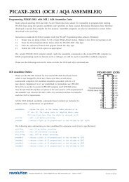
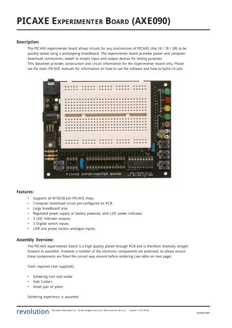
<strong>PICAXE</strong> <strong>EXPERIMENTER</strong> <strong>BOARD</strong> (<strong>AXE090</strong>)Description:The <strong>PICAXE</strong> experimenter board allows circuits for any size/revision of <strong>PICAXE</strong> chip (8 / 18 / 28) to bequickly tested using a prototyping breadboard. The experimenter board provides power and computerdownload connections, aswell as simple input and output devices for testing purposes.This datasheet provides construction and circuit information for the Experimenter board only. Pleasesee the main <strong>PICAXE</strong> manuals for information on how to use the software and how to build circuits.Features:• Supports all 8/18/28 pin <strong>PICAXE</strong> chips.• Computer download circuit pre-configured on PCB.• Large breadboard area.• Regulated power supply or battery powered, with LED power indicator.• 3 LED indicator outputs.• 3 Digital switch inputs.• LDR and preset resistor analogue inputs.Assembly Overview:The <strong>PICAXE</strong> experimenter board is a high quality plated through PCB and is therefore relatively straightforward to assemble. However a number of the electronic components are polarised, so please ensurethese components are fitted the correct way around before soldering (see table on next page).Tools required (not supplied):• Soldering iron and solder• Side Cutters• Small pair of pliersSoldering experience is assumed.revolution Revolution Education Ltd. Email: info@rev-ed.co.uk Web: www.rev-ed.co.uk Version 1.5 27/10/04 <strong>AXE090</strong>.PMD
<strong>PICAXE</strong> <strong>EXPERIMENTER</strong> <strong>BOARD</strong>2Contents:• PCB <strong>PICAXE</strong> Experimenter PCB• BB self adhesive protoboard (breadboard) *** align text correct way up• ICH08 8 pin IC socket (supplied on BB)• ICH18 18 pin IC socket “• ICH28 28 pin IC socket “• IC1 <strong>PICAXE</strong>-18X microcontroller “• H1-2 20 pin SIL connector (x2)• H3 10 pin SIL connector• A1 10k 5 pin resistor array *** text on one side of device• A2 330R 8 pin resistor array *** text on one side of device• R1 22k resistor (red red orange gold)• R2 10k resistor (brown black orange gold)• R3 4k7 resistor (yellow violet red gold)• R4 180 resistor (brown grey brown gold)• C1 100uF electrolytic capacitor *** +, - marked on PCB• C2 100nF (104) polyester capacitor• RG1 7805 5V voltage regulator *** text on device faces up• L3 red 5mm LED *** flat marked on PCB• L2 yellow 5mm LED *** flat marked on PCB• L1, PWR green 5mm LED (x2) *** flat marked on PCB• X1 4MHz 3 pin ceramic resonator• D1 1N4001 diode *** bar end marked on PCB• D2 BAT85 schottky diode *** bar end marked on PCB• LDR miniature LDR• POT 100k preset pot resistor• SW1-4 miniature push switch (x4)• CONN3 2.1mm power socket• CONN2 3.5mm stereo socket• CONN1 2 pin screw terminal block• AXE026 <strong>PICAXE</strong> serial cable(*** denotes components which must be soldered the correct way around. See notes above).(Parts D2 and R4 are only fitted on PCB version 1D and later)Assembly Instructions:1. Solder the resistors and two diodes in position, ensuring correct polarity of the diodes.2. Solder the two resistor arrays in position, ensuring correct polarity of the ‘dot’ marker (shown on thetext side of the device). The text side of both devices should ‘face’ the LED positions.3. Solder the three IC sockets in position. Solder the 10 pin, and the two 20 pin, SIL connectors inposition.4. Solder the capacitors and 7805 voltage regulator in place. Ensure the voltage regulator is connected thecorrect way around (text facing up).5. Solder the LEDs, resonator, LDR and preset pot in position. Ensure correct polarity of the LEDs.6. Solder the switches and connectors in place. Ensure the CONN2 stereo socket ‘clicks’ into position flaton the PCB prior to soldering (it does not matter if solder joins the two ‘pairs’ of contacts each side).7. Peel the protective paper off the rear of the breadboard and use the self adhesive layer to carefully stickthe breadboard in position (ensure the text is the correct way up).8. Insert the <strong>PICAXE</strong>-18X microcontroller supplied into the 18 pin socket, pin1 to the left.revolution Revolution Education Ltd. Email: info@rev-ed.co.uk Web: www.rev-ed.co.uk Version 1.5 27/10/04 <strong>AXE090</strong>.PMD
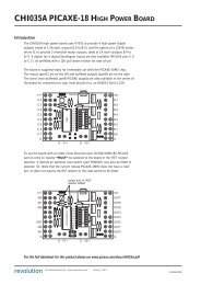
<strong>PICAXE</strong> <strong>EXPERIMENTER</strong> <strong>BOARD</strong>3Circuit Diagram (<strong>PICAXE</strong>-08/08M):5V12310k22k1serial in2in / out 4 3in 3 4088765serial outout 0in / out 1in / out 20V3 2 1CableconnectionCircuit Diagram (<strong>PICAXE</strong>-18/18A/18X):5V4k722kin 2serial outserial in123181716in 1in 0in 712310kout 0out 1out 245678<strong>PICAXE</strong>-181514131211in 6out 7out 6out 5resetout 3910out 40VCircuit Diagram (<strong>PICAXE</strong>-28A/28X):5V4k7128out 7ADC 0227out 6ADC 1326out 5ADC 2425out 4ADC 3524out 312310k22kserial in 6serial out 7894MHz10in 0 11<strong>PICAXE</strong>-28232221201918out 2out 1out 0in 7in 11217in 6in 21316in 5in 31415in 4reset0Vrevolution Revolution Education Ltd. Email: info@rev-ed.co.uk Web: www.rev-ed.co.uk Version 1.5 27/10/04 <strong>AXE090</strong>.PMD
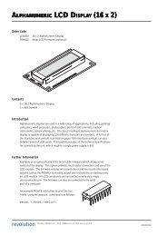
<strong>PICAXE</strong> <strong>EXPERIMENTER</strong> <strong>BOARD</strong>4Using the Experimenter Board:Important Notes:1. Only one size of <strong>PICAXE</strong> chip should be fitted at any one time.2. Only one power source should be connected at any one time.3. <strong>PICAXE</strong> chip polarity (pin 1 to left) should be observed at all times.Failure to observe any of these points may result in damage to the <strong>PICAXE</strong> chip.<strong>PICAXE</strong> Input/Output Pin Connections:The <strong>PICAXE</strong>-08 has its own input/output pin connection points. The <strong>PICAXE</strong>-18and <strong>PICAXE</strong>-28 share pin connection points. The serial in (RCV) and serial out(TXD) signals from the download socket are connected directly to all three<strong>PICAXE</strong> chip sockets via tracks on the PCB. (NB Version 1d PCB now uses the‘enhanced’ download circuit with additional resistor R4 and shottky diode D2.See the <strong>PICAXE</strong> manual for more details about this enhanced circuit.)To make connections between the input/output pin headers and the breadboardit is recommended that 1/0.6mm single core equipment wire is used. Do notplace component legs (e.g. resistors) directly in the input/output pin headers asthe leg of the component may not be thick enough to make a reliable connectionwithin the header. Use the wire to connect to the breadboard, and then place thecomponent in the breadboard.<strong>PICAXE</strong>-08 / 08MThe <strong>PICAXE</strong>-08 input/output connections are on the left hand side of the board,marked OUT0, I/O1, I/O2, IN3 and I/O4. Note that OUT0 is also connected toTXD and so will flicker when a download is taking place (<strong>PICAXE</strong>-08/08M only).<strong>PICAXE</strong>-18 / 18A / 18XThe <strong>PICAXE</strong>-18 input / output connections are as follows:OUT0 to OUT7 outputsIN0, IN1, IN2 digital inputs or analogue inputsIN6, IN7digital inputsRSTreset(IN3-5 and ADC0-3 are not used).<strong>PICAXE</strong>-28 / 28A / 28XThe <strong>PICAXE</strong>-28 input / output connections are as follows:OUT0 to OUT7 outputsIN0 to IN7 digital inputsADC0-ADC3 analogue inputsRSTreset+VSerial InPin 4Pin 3Input 2Serial OutSerial InReset0VOutput 0Output 1Output 2Output 3ResetAnalogue 0Analogue 1Analogue 2Analogue 3Serial InSerial Out0VResonatorResonatorInput 0Input 1Input 2Input 3<strong>PICAXE</strong>-081234<strong>PICAXE</strong>-181234567898765181716151413121110<strong>PICAXE</strong>-28123456789101112131428272625242322212019181716150VPin 0 / Serial OutPin 1Pin 2Input 1Input 0Input 7Input 6+VOutput 7Output 6Output 5Output 4Output 7Output 6Output 5Output 4Output 3Output 2Output 1Output 0+V0VInput 7Input 6Input 5Input 4www.picaxe.co.uk(c) Rev-Ed Ltd 2002Computer Connection:Only use the AXE026 <strong>PICAXE</strong> serial cable. For USB connection, the USB to serialadapter (part USB010) is also required.Reset Switch:The reset switch only resets <strong>PICAXE</strong> chips with a reset pin (18 and 28). To resetthe <strong>PICAXE</strong>-08/08M you must disconnect and reconnect the battery (or powersupply). The reset switch also has a header connection marked RST.revolution Revolution Education Ltd. Email: info@rev-ed.co.uk Web: www.rev-ed.co.uk Version 1.5 27/10/04 <strong>AXE090</strong>.PMD
<strong>PICAXE</strong> <strong>EXPERIMENTER</strong> <strong>BOARD</strong>5Power Supply:There are two options on how to provide power to the Experimenter board, butensure only one option is connected at any one time. The PWR LED indicatespower to the board.1. Battery - connect a 4.5V (3xAA cell, not supplied) battery box to the screwterminals, ensuring correct polarity. Do not use 6 or 9V battery packs.2. Power supply - connect a regulated 9V DC power supply with 2.1mm(positive tip) connector (not supplied e.g. part PWR009).The power supply connection is regulated to 5V by the 7805 regulatorand reverse polarity protected by a diode.The screw terminal battery connection is not regulated and so connectsdirectly to the <strong>PICAXE</strong> chip. Do not use a 9V PP3 battery on thisconnection. Only use a 4.5V (not 6V) battery pack.Input and Output Devices:Output - LEDsThree LEDs are provided (L1 to 3). The LED will light when a positivesignal is applied. The cathode of the LED is connected by a 330R resistorto 0V.Digital Input - SwitchesThree switches are provided (SW1 to 3). The input is tied low by a 10k resistor,with the switch connected between the input and V+. Therefore pressing theswitch will result in a high signal.pin0VV+330RAnalogue Input - LDRThe LDR is arranged with a 10k resistor in a potential divider arangement. TheLDR is connected between the input and V+, the resistor between the input and0V.Analogue Input - Preset PotThe preset pot is a 100k device connected directly between the V+ and 0V powerrails. The wiper of the preset pot is connected to the input.Prototyping board (breadboard):The prototyping board (breadboard) has 60 sets of connection points and 4power rails.The breadboard has 60 sets of vertical 5 hole connection sets (30 top sets and 30bottom sets) for making connections. The vertical sets are not connected acrossthe centre of the breadboard.10k10kV+Pin0VminiatureLDRpin0VThe breadboard has 4 sets of horizontal 25 hole power rails (2 top sets and 2bottom sets). The horizontal sets are connected all the way across the top(bottom) of the breadboard. The four rails are all independant (not connected).Power connection points (marked V+ and 0V) are provided on the header besidethe ends of the power rails for connecting power to the breadboard rails.revolution Revolution Education Ltd. Email: info@rev-ed.co.uk Web: www.rev-ed.co.uk Version 1.5 27/10/04 <strong>AXE090</strong>.PMD