You also want an ePaper? Increase the reach of your titles
YUMPU automatically turns print PDFs into web optimized ePapers that Google loves.
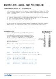
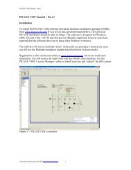
LD1117ASERIESLOW DROP FIXED AND ADJUSTABLEPOSITIVE VOLTAGE REGULATORS■ LOW DROPOUT VOLTAGE(1.15V TYP. @ I OUT =1A,25°C)■ VERY LOW QUIESCENT CURRENT(5 mA TYP. @ 25°C)■ OUTPUT CURRENT UP TO 1A■ FIXED OUTPUT VOLTAGE OF: 1.8V, 2.5V,2.85V, 3.3V, 5.0V■ ADJUSTABLE VERSION AVAILABILITY(V rel = 1.25V)■ INTERNAL CURRENT AND THERMAL LIMIT■ ONLY 10 µF FOR STABILITY■ AVAILABLE IN ± 2% (AT 25°C) AND 4% INFULL TEMPERATURE RANGE■ HIGH SUPPLY VOLTAGE REJECTION:(80dB TYP. AT 25°C)■ TEMPERATURE RANGE: 0°C TO 125°CSOT-223DPAKTO-220DESCRIPTIONThe LD1117A is a LOW DROP Voltage Regulatorable to provide up to 1A of Output Current,available even in adjustable version (Vref=1.25V).Concerning fixed versions, are offered thefollowing Output Voltages: 1.8V, 2.5V, 2.85V,3.3V and 5.0V. The 2.85V type is ideal for SCSI-2lines active termination. The device is supplied in:SOT-223, DPAK and TO-220. The surface mountpackages optimize the thermal characteristicseven offering a relevant space saving effect. Highefficiency is assured by NPN pass transistor. Onlya very common 10µF minimum capacitor isneeded for stability. Only chip trimming allows theregulator to reach a very tight output voltagetolerance, within ± 2% at 25 °C.BLOCK DIAGRAMJanuary 20031/16
LD1117A SERIESABSOLUTE MAXIMUM RATINGSSymbol Parameter² Value UnitV IN DC Input Voltage 10 VP tot Power Dissipation 12 WT stg Storage Temperature Range -40 to +150 °CT op Operating Junction Temperature Range 0 to +125 °CAbsolute Maximum Ratings are those values beyond which damage to the device may occur. Functional operation under these condition isnot implied. Over the above suggested Max Power Dissipation a Short Circuit could definitively damage the device.THERMAL DATASymbol Parameter TO-220 SOT-223 DPAK UnitR thj-case Thermal Resistance Junction-case 3 15 8 °C/WR thj-amb Thermal Resistance Junction-ambient 50 °C/WAPPLICATION CIRCUIT (FOR OTHER FIXED OUTPUT VOLTAGES)2/16
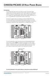
LD1117A SERIESCONNECTION DIAGRAM (top view)DPAKSOT-223TO-220NOTE: The TAB is connected to the V OUT .ORDERING CODESSOT-223 DPAK TO-220 OUTPUT VOLTAGELD1117AS18TR LD1117ADT18TR LD1117AV18 1.8 VLD1117AS25TR LD1117ADT25TR LD1117AV25 2.5 VLD1117AS28TR LD1117ADT28TR LD1117AV28 2.85 VLD1117AS33TR LD1117ADT33TR LD1117AV33 3.3 VLD1117AS50TR LD1117ADT50TR LD1117AV50 5 VLD1117AST-R LD1117ADT-R LD1117AV ADJUSTABLE FROM 1.25TO 15 V3/16
LD1117A SERIESELECTRICAL CHARACTERISTICS OF LD1117A#18 (refer to the test circuits, T J = 0 to 125°C,C O =10µF,C I = 10 µF unless otherwise specified)60 80 dBSymbol Parameter Test Conditions Min. Typ. Max. UnitV O Output Voltage V I = 3.8 V I O =10mA T J = 25°C 1.764 1.8 1.836 VV O Output Voltage I O =0to1A V I = 3.3 to 8 V 1.728 1.872 V∆V O Line Regulation V I = 3.3 to 8 V I O = 0 mA 1 6 mV∆V O Load Regulation V I = 3.3 V I O = 0 to 1 A 1 10 mV∆V O Temperature Stability 0.5 %∆V O Long Term Stability 1000 hrs, T J = 125°C 0.3 %V I Operating Input Voltage I O = 100 mA 10 VI d Quiescent Current V I ≤ 8V I O = 0 mA 5 10 mAI O Output Current V I -V O =5VT J = 25°C 1000 mAeN Output Noise Voltage B =10Hz to 10KHz T J = 25°C 100 µVSVR Supply Voltage Rejection I O = 40 mA f = 120HzV I -V O =3V V ripple =1V PPV D Dropout Voltage I O = 100 mA 1 1.10 VI O = 500 mA 1.05 1.15I O = 1 A 1.15 1.30∆V O(pwr) Thermal Regulation T a = 25°C 30ms Pulse 0.08 0.2 %/WELECTRICAL CHARACTERISTICS OF LD1117A#25 (refer to the test circuits, T J = 0 to 125°C,C O =10µF,C I = 10 µF unless otherwise specified)60 80 dBSymbol Parameter Test Conditions Min. Typ. Max. UnitV O Output Voltage V I = 4.5 V I O =10mA T J = 25°C 2.45 2.5 2.55 VV O Output Voltage I O =0to1A V I = 3.9 to 8 V 2.4 2.6 V∆V O Line Regulation V I = 3.9 to 8 V I O = 0 mA 1 6 mV∆V O Load Regulation V I = 3.9 V I O = 0 to 1 A 1 10 mV∆V O Temperature Stability 0.5 %∆V O Long Term Stability 1000 hrs, T J = 125°C 0.3 %V I Operating Input Voltage I O = 100 mA 10 VI d Quiescent Current V I ≤ 10 V I O = 0 mA 5 10 mAI O Output Current V I -V O =5VT J = 25°C 1000 1200 mAeN Output Noise Voltage B =10Hz to 10KHz T J = 25°C 100 µVSVR Supply Voltage Rejection I O = 40 mA f = 120HzV I -V O =3V V ripple =1V PPV D Dropout Voltage I O = 100 mA 1 1.10 VI O = 500 mA 1.05 1.15I O = 1 A 1.15 1.30∆V O(pwr) Thermal Regulation T a = 25°C 30ms Pulse 0.08 0.2 %/W4/16
LD1117A SERIESELECTRICAL CHARACTERISTICS OF LD1117A#28 (refer to the test circuits, T J = 0 to 125°C,C O =10µF,C I = 10 µF unless otherwise specified)60 75 dBSymbol Parameter Test Conditions Min. Typ. Max. UnitV O Output Voltage V I = 4.85 V I O =10mA T J = 25°C 2.793 2.85 2.907 VV O Output Voltage I O =0to1A V I = 4.25 to 10 V 2.736 2.964 V∆V O Line Regulation V I = 4.25 to 8 V I O = 0 mA 1 6 mV∆V O Load Regulation V I = 4.25 V I O = 0 to 1 A 1 10 mV∆V O Temperature Stability 0.5 %∆V O Long Term Stability 1000 hrs, T J = 125°C 0.3 %V I Operating Input Voltage I O = 100 mA 10 VI d Quiescent Current V I ≤ 10 V I O = 0 mA 4.5 10 mAI O Output Current V I -V O =5VT J = 25°C 1000 1200 mAeN Output Noise Voltage B =10Hz to 10KHz T J = 25°C 100 µVSVR Supply Voltage Rejection I O = 40 mA f = 120HzV I -V O =3V V ripple =1V PPV D Dropout Voltage I O = 100 mA 1 1.10 VI O = 500 mA 1.05 1.15I O = 1 A 1.15 1.30∆V O(pwr) Thermal Regulation T a = 25°C 30ms Pulse 0.08 0.2 %/WELECTRICAL CHARACTERISTICS OF LD1117A#33 (refer to the test circuits, T J = 0 to 125°C,C O =10µF,C I = 10 µF unless otherwise specified)60 75 dBSymbol Parameter Test Conditions Min. Typ. Max. UnitV O Output Voltage V I = 5.3 V I O =10mA T J = 25°C 3.234 3.3 3.366 VV O Output Voltage I O =0to1A V I = 4.75 to 10 V 3.168 3.432 V∆V O Line Regulation V I = 4.75 to 8 V I O = 0 mA 1 6 mV∆V O Load Regulation V I = 4.75 V I O = 0 to 1 A 1 10 mV∆V O Temperature Stability 0.5 %∆V O Long Term Stability 1000 hrs, T J = 125°C 0.3 %V I Operating Input Voltage I O = 100 mA 10 VI d Quiescent Current V I ≤ 10 V I O = 0 mA 5 10 mAI O Output Current V I -V O =5VT J = 25°C 1000 1200 mAeN Output Noise Voltage B =10Hz to 10KHz T J = 25°C 100 µVSVR Supply Voltage Rejection I O = 40 mA f = 120HzV I -V O =3V V ripple =1V PPV D Dropout Voltage I O = 100 mA 1 1.10 VI O = 500 mA 1.05 1.15I O = 1 A 1.15 1.30∆V O(pwr) Thermal Regulation T a = 25°C 30ms Pulse 0.08 0.2 %/W5/16
LD1117A SERIESELECTRICAL CHARACTERISTICS OF LD1117A#50 (refer to the test circuits, T J = 0 to 125°C,C O =10µF,C I = 10 µF unless otherwise specified)60 80 dBSymbol Parameter Test Conditions Min. Typ. Max. UnitV O Output Voltage V I =7V I O =10mA T J = 25°C 4.9 5 5.1 VV O Output Voltage I O =0to1A V I = 6.4 to 10 V 4.8 5.2 V∆V O Line Regulation V I = 6.4 to 8 V I O = 0 mA 1 6 mV∆V O Load Regulation V I = 6.4 V I O = 0 to 1 A 1 10 mV∆V O Temperature Stability 0.5 %∆V O Long Term Stability 1000 hrs, T J = 125°C 0.3 %V I Operating Input Voltage I O = 100 mA 10 VI d Quiescent Current V I ≤ 10 V I O = 0 mA 5 10 mAI O Output Current V I -V O =5VT J = 25°C 1000 1200 mAeN Output Noise Voltage B =10Hz to 10KHz T J = 25°C 100 µVSVR Supply Voltage Rejection I O = 40 mA f = 120HzV I -V O =3V V ripple =1V PPV D Dropout Voltage I O = 100 mA 1 1.10 VI O = 500 mA 1.05 1.15I O = 1 A 1.15 1.30∆V O(pwr) Thermal Regulation T a = 25°C 30ms Pulse 0.08 0.2 %/WELECTRICAL CHARACTERISTICS OF LD1117A (ADJUSTABLE) (refer to the test circuits, T J =0to125°C, C O =10µF,C I = 10 µF unless otherwise specified)60 80 dBSymbol Parameter Test Conditions Min. Typ. Max. UnitV O Output Voltage V I = 5.3 V I O =10mA T J = 25°C 1.225 1.25 1.275 VV O Output Voltage I O =0to1A V I = 2.75 to 10 V 1.2 1.3 V∆V O Line Regulation V I = 2.75 to 8 V I O = 0 mA 1 6 mV∆V O Load Regulation V I = 2.75 V I O = 0 to 1 A 1 10 mV∆V O Temperature Stability 0.5 %∆V O Long Term Stability 1000 hrs, T J = 125°C 0.3 %V I Operating Input Voltage I O = 100 mA 10 VI d Quiescent Current V I ≤ 8V I O = 0 mA 5 10 mAI O Output Current V I -V O =5VT J = 25°C 1000 1200 mAeN Output Noise Voltage B =10Hz to 10KHz T J = 25°C 100 µVSVR Supply Voltage Rejection I O = 40 mA f = 120HzV I -V O =3V V ripple =1V PPV D Dropout Voltage I O = 100 mA 1 1.10 VI O = 500 mA 1.05 1.15I O = 1 A 1.15 1.30∆V O(pwr) Thermal Regulation T a = 25°C 30ms Pulse 0.08 0.2 %/W6/16
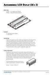
LD1117A SERIESTYPICAL APPLICATIONSFigure 1 : Negative SupplyFigure 2 : Active Terminator for SCSI-2 BUSFigure 3 : Circuit for Increasing Output Voltage7/16
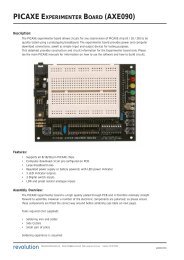
LD1117A SERIESFigure 4 : Voltage Regulator With ReferenceFigure 5 : Battery Backed-up Regulated Supply8/16
LD1117A SERIESFigure 6 : Post-Regulated Dual Supply9/16
LD1117A SERIESDPAK MECHANICAL DATADIM.mm.inchMIN. TYP MAX. MIN. TYP. MAX.A 2.2 2.4 0.086 0.094A1 0.9 1.1 0.035 0.043A2 0.03 0.23 0.001 0.009B 0.64 0.9 0.025 0.035B2 5.2 5.4 0.204 0.212C 0.45 0.6 0.017 0.023C2 0.48 0.6 0.019 0.023D 6 6.2 0.236 0.244E 6.4 6.6 0.252 0.260G 4.4 4.6 0.173 0.181H 9.35 10.1 0.368 0.397L2 0.8 0.031L4 0.6 1 0.023 0.0390068772-B12/16
LD1117A SERIESTO-220 MECHANICAL DATADIM.mm.inchMIN. TYP MAX. MIN. TYP. MAX.A 4.40 4.60 0.173 0.181C 1.23 1.32 0.048 0.051D 2.40 2.72 0.094 0.107D1 1.27 0.050E 0.49 0.70 0.019 0.027F 0.61 0.88 0.024 0.034F1 1.14 1.70 0.044 0.067F2 1.14 1.70 0.044 0.067G 4.95 5.15 0.194 0.203G1 2.4 2.7 0.094 0.106H2 10.0 10.40 0.393 0.409L2 16.4 0.645L4 13.0 14.0 0.511 0.551L5 2.65 2.95 0.104 0.116L6 15.25 15.75 0.600 0.620L7 6.2 6.6 0.244 0.260L9 3.5 3.93 0.137 0.154DIA. 3.75 3.85 0.147 0.151P011C13/16
LD1117A SERIESTape & Reel SOT223 MECHANICAL DATADIM.mm.inchMIN. TYP MAX. MIN. TYP. MAX.A 180 7.086C 12.8 13.0 13.2 0.504 0.512 0.519D 20.2 0.795N 60 2.362T 14.4 0.567Ao 6.73 6.83 6.93 0.265 0.269 0.273Bo 7.32 7.42 7.52 0.288 0.292 0.296Ko 1.78 2 0.070 0.078Po 3.9 4.0 4.1 0.153 0.157 0.161P 7.9 8.0 8.1 0.311 0.315 0.31914/16
LD1117A SERIESTape & Reel DPAK-PPAK MECHANICAL DATADIM.mm.inchMIN. TYP MAX. MIN. TYP. MAX.A 180 7.086C 12.8 13.0 13.2 0.504 0.512 0.519D 20.2 0.795N 60 2.362T 14.4 0.567Ao 6.80 6.90 7.00 0.268 0.272 0.2.76Bo 10.40 10.50 10.60 0.409 0.413 0.417Ko 2.55 2.65 2.75 0.100 0.104 0.105Po 3.9 4.0 4.1 0.153 0.157 0.161P 7.9 8.0 8.1 0.311 0.315 0.31915/16
LD1117A SERIESInformation furnished is believed to be accurate and reliable. However, STMicroelectronics assumes no responsibility for theconsequences of use of such information nor for any infringement of patents or other rights of third parties which may result fromits use. No license is granted by implication or otherwise under any patent or patent rights of STMicroelectronics. Specificationsmentioned in this publication are subject to change without notice. This publication supersedes and replaces all informationpreviously supplied. STMicroelectronics products are not authorized for use as critical components in life support devices orsystems without express written approval of STMicroelectronics.© The ST logo is a registered trademark of STMicroelectronics© 2003 STMicroelectronics - Printed in Italy - All Rights ReservedSTMicroelectronics GROUP OF COMPANIESAustralia - Brazil - Canada - China - Finland - France - Germany - Hong Kong - India - Israel - Italy - Japan - Malaysia - Malta - MoroccoSingapore - Spain - Sweden - Switzerland - United Kingdom - United States.© http://www.st.com16/16