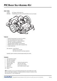
Picaxe Micromouse Kit
Picaxe Micromouse Kit
Picaxe Micromouse Kit
- No tags were found...

You also want an ePaper? Increase the reach of your titles
YUMPU automatically turns print PDFs into web optimized ePapers that Google loves.
What is <strong>Micromouse</strong> ?<strong>Micromouse</strong> is an event where small autonomous robot mice compete against each other to solve a maze. The mazeconsists of 18cm square cells with 5cm high walls set over a 16 by 16 grid. The mice must find their way unassisted fromthe set start corner of a maze with an unknown layout, to the centre. As they search the maze mice track their position andplot walls as they discover them to map the optimal route. Once the route has been discovered the mouse returns to thestart square and runs this path in the shortest possible time. Mircomouse events are regularly held in schools, colleges,universities and exhibition centres around the world. Details of the UK championships can be found atwww.tic.ac.uk/micromouse.Although a similar challenge was held in 1979, it was not until 1980 at the Euromicro event in London UK, that theuniversal maze sizes and centre goal squares were set. This became the challenge that is <strong>Micromouse</strong> as we know it today.Over the years the challenge to create an autonomous robot that can solve a maze has spread worldwide with regularinternational championships. The original challenge was to find the centre of the maze (which in itself demands skills inmicro robotics and programming), but over the years the events have developed into a race to the centre, with micecapable of speeds in excess of 3 metres per second.Introducing The Maze Solving <strong>Micromouse</strong> <strong>Kit</strong>This low cost <strong>Micromouse</strong> kit is designed for both students and amateur enthusiasts. It demonstrates computer controlresponding to an external environment and has been developed and designed by the 2007 UK <strong>Micromouse</strong> championsDerek Hall and Jim Chidley.The kit features detailed photo construction plans in easy-to-follow stages, programming in BASIC with Flowchartdiagrams to assist understanding and instructions and tips on fine-tuning. The key design elements are fully explainedproviding you with everything you require to build a robot mouse, setting a minimum benchmark for all Micromice.
The kit is an ideal introduction into computer control. It shows BASIC program equivalents to Flowchart constructs anddemonstrates D&T techniques in easy stages to aid understanding. The kit offers a simple solution to a complex problembut it requires a degree of competence in soldering. Care will be needed during construction and it is advisable to use awell-lit desk and a fine-tipped soldering iron.To complete construction you will require the following:• Download cable.• PP3 9v alkaline battery or equivalent.• Fine tipped soldering iron and solder.• Hot melt glue gun.• Contact adhesive.• Small ruler and craft knife.• Wire cutters / small screwdrivers.• Small piece of kitchen foil and a drop of oil.If you are using the software provided, you will require both the <strong>Picaxe</strong> 28X1 and the <strong>Picaxe</strong> 18X. It is possible tocompile the program so that it can be run on just the <strong>Picaxe</strong> 28X1. This will lose the advantage of being able to split thesoftware into two separate programs for easy development; possibly with separate teams working on control and mazesolving. The serial download cable can be ordered from www.picaxe.co.uk . The free program editing software can alsobe downloaded from this site.• <strong>Micromouse</strong> is comparable to many state-of-the-art technologies, from autonomous factory vehicles to planetaryexploration. Important skills learned from the construction and control of Micromice can also be directly appliedto both current and future car design.• The maze-solving algorithm used in Micromice finds the shortest route from the current position to a destinationand re-routes when it finds a blocked path. This algorithm is used in applications such as satellite navigation androute finding on the roads.• Parking sensors on cars are becoming commonplace to detect obstacles. Advanced systems go as far as parkingthe car for you, while many millions of dollars are currently being invested globally in developing totallyautonomous (driverless) cars. In 2007, the DARPA Urban Challenge proved the abilities of computer-controlledcars with a first prize of $2 million.• Battery powered DC motors are now being use in cars, demonstrating the abilities of a non-polluting energysource. In 2006 Tesla Motors announced the production of the Tesla Roadster. It uses Lithium Ion batteries totravel 245 miles on one charge, accelerate from 0-60 in under 4 seconds and give a top speed of 135 mph.• As part of a training exercise, which could lead to evaluations of potential outposts on the Moon or Mars, Nasahas been sending robots to an isolated rocky polar desert, within a crater in the Arctic Circle. These vehicles arerequired to be autonomous in case communication is lost.• Automated guided vehicles are becoming commonplace in a factory environment helping to reduce costs ofmanufacturing and increase efficiency.
THIS COMPLETE MANUAL IS ALSO IN PDF FORMAT ON THE CD.Stage 1Assemble the motor and gearbox components as detailed below. The steel axles will need to be each cut down to42 mm in length with a hacksaw. Take special care when positioning the counters.Fig 1 Fig 2Twist motorNote the worminto place togears are notfit flush.pushed tightagainst themotors allowabout a 3mmgap.Fig 3Fig4Make sureA small piece of blackthe wheelscard is secured using aare not contact adhesive. Be . Bepushed toocareful not to get anytightlyglue on the teeth of theagainstworm gear. Once thethe sideglue has dried carefullyassembly.trim the card to thesame width as the gear.Fig 5Now glue smallpieces of kitchenfoil with theshinny side upto coverhalf of the blackcard, and trim tosize when dry.Fig 6The black and silverdiscs form the wheelcounters and shouldbe as close to half andhalf as possible, toensure the counts areas even.Temporally push the motor gear assembly intoposition through the PCB and screw it intoplace. At point “A” the worm gears shouldhave about 1 mm clearance from the PCB. Toadjust place a small flat head screwdriver atpoint “B” and slowly turn it. This will ease thegear into to right place.The small IR phototransistor receives pulses asthe motor turns. This is counted by theprocessor. Both ON and OFF pulses arecounted for manoeuvres, but it is onlynecessary to count the ON pulses (61 countsper square) when travelling in a straight line.Remember to allow for the internal play in the motor when setting the distance at point ”A”. As the motor stops and starts the wormgear will move up and down, this may rub the foil off on the PCB causing the wheel counters to fail and your mouse to turncontinually.• An alternative to the foil and black card can be found in additional information at the end of this manual.
Fig 4• Capacitors x3 C2,C3,C4• Push buttons x3 button “A”, “B” and START• ON/OFF Slide switch• Voltage regulator CHECK ORIENTATION STATICSENSITIVE• CHECK ORIENTATION (the grey strip is negativeand goes as shown.)A resonator may be added at a later date but this is notnecessary for the completion of this kit. See additionalinformation at the end of this manual or Help in <strong>Picaxe</strong>programming editor for more details.Fig 5• Colour LEDs Red x2, Greenx2, Yellow x1 with built inresistors CHECKORIENTATION (the shorterleg is the cathode and connectsto ground, use pictures belowas guide)REDGREENREDYELLOWGREENFig 6• Mount the motor / gearbox assembly (align theholes up and screw to attach)
Fig 7• Solder the motor wires as shown.BLACK-L =Left motor black wireRED-L =Left motor red wireBLACK-R =Right motor black wireRED-R =Right motor red wire• Jack sockets x2. (Each <strong>Picaxe</strong> needs a separatedownload jack plug)• Relay. (the right hand motor is reversed by the relay,allowing the mouse to turn on the spot)Fig 8• IR LEDs x3. (Cut shrink wrap to two 7mm lengths and slide over two LEDsfor side wall sensing. These will help narrow the beam for the side sensorscreating a sharper image as the wall disappears.) Bend the LED legs to fit asshown below do not have the LED’s protruding passed the edge of the PCB.Notice the side the short leg cathode is on.Fig 9• Drawing pins x2. Attach the front drawing pin first ensuring the light tovoltage converters are at lest 2mm from the ground to help reduce unwantedIR reflection from the maze base. also take care not to short circuit anycomponent legs. Locate the small holes (without pads) for position, thepoint of the drawing pin should be slightly below the top surface of thePCB, push the drawing pins in allowing your mouse to rock very slightlyby 1 or 2 mm, additional securing may be added using a glue gun.• M3 Screw peg. (this will secure the battery when in place)Do not power up your mouse for any length of time until you are readyto download a test program into it, as this may damage the IR LEDs.Use a tiny amount of glue at the back ofthe LED to secure shrink-wrap in place.Construction is complete.Fig 10• Carefully insert the two driver chips and two <strong>Picaxe</strong> chips.CHECK ORIENTATION STATIC SENSITIVE
Test routinesThere are 3 test programs and 2 final programs on the CD-rom supplied. The tests are all in BASIC with some Flowchartequivalents. By examining the flowcharts you can follow the program broken down to its simplest form. This will aid inthe understanding of how the program works. Work your way through the tests ensuring components work and themanoeuvres are as accurate as possible. If you require any more information on any of the commands selectHELP/BASIC COMMANDS in the <strong>Picaxe</strong> programming editor.Once all the tests are completed your mouse will be ready to run. It is important to remember that calibration of thestraightening values and front sensor reading may need to be adjusted if you run your mouse in a maze with different wallcoatings (painted or plastic).Hardware diagnostic Tests 1 and 2TEST 1 <strong>Picaxe</strong> 28X1• Load up <strong>Picaxe</strong> program TEST 1 into <strong>Picaxe</strong>programming editor.• Check 28X1 is selected in VIEW / OPTIONS.• Switch on your mouse.• Insert download cable into 28X1 jack socket.• Press F5 to run program. (Whilstdownloading the program into <strong>Picaxe</strong>, holdyour mouse off the ground as the motors mayturn at random).• Right, Middle and Left LED’s now stay on.Select correct <strong>Picaxe</strong>PICAXE 18XPICAXE 28X1TEST 2 <strong>Picaxe</strong> 18X• Load up <strong>Picaxe</strong> program TEST 2 into <strong>Picaxe</strong>programming editor.• Check 18X is selected in VIEW / OPTIONS.• Switch on your mouse.• Insert download cable into 18X jack socket.• Press F5 to run program. (Whilstdownloading the program into <strong>Picaxe</strong>, holdyour mouse off the ground as the motors mayturn at random).• LED 1 and LED 2 now flash alternatively.With the power switch still on press button“B”(reset). This will cause all five LEDs to gooff while it is held down. Button “A” will stopLED 1 and LED 2 from flashing.
TEST 1 and 2 are diagnostic tests designed to test that all the elements of control and sensing are working correctly. Byfollowing the instructions below you will highlight any construction errors that may have occurred. Run the test modeonly for a few minutes at a time, as the voltage regulator may start to get hot and your battery life will suffer.• Testing buttons “A” and infrared LEDs and sensors.Press button “A”. LEDs 1 and 2 will now go out. Press “Start” button. Left, middle and right LEDs go off. Thecorresponding LEDs will light up if an object is brought close enough to be detected by the left, middle and right wallsensors.• Testing motors and left wheel counter.Hold your mouse off the ground and press the “Start” button. Both wheels turn in a forward direction. The left LEDflashes on and off every 20 left wheel counts. Moving the worm gear away from the sensor will increase the time theLED is off, try to make the on/off time similar.• Testing right wheel counter.With your mouse still off the ground press the “Start” button. Both wheels turn in a forward direction. The right LEDflashes on and off every 20 right wheel counts. Moving the worm gear away from the sensor will increase the time theLED is off, try to make the on/off time similar.• Testing relay to reverse right wheel.With your mouse still off the ground press the “Start” button. Right wheel reverses for half a second then continuesforward for half a second and then repeats.• Testing serial communications between <strong>Picaxe</strong>28X1 and <strong>Picaxe</strong>18X.Press “Start” button. Middle, 1 and 2 LEDs light for 1 second then go off simultaneously. This then repeats continually.Press button “B”(reset) to restart test sequence.At this point a very tiny drop ofoil may be applied to the wormgear and axle holes to smoothmeshing. Use a small flatscrewdriver to apply the oilwhile the motors are turning. Becareful not to damage the gearsor use too much as this maycause your wheel counters tocome unstuck.Apply minimal oil to these points.Simple faultfinding• Ensure correct <strong>Picaxe</strong> is selected during programming in VIEW / OPTIONS and the correct jack socket is selected.• Use a resistance meter to check your soldering for dry joints and solder bridges between track or pads. Check electricalcomponents have been assembled correctly and that component legs are cut short and not touching each other.• Check gear and wheels are not rubbing against circuit board or gear assembly.• Check worm gear is not too far away from phototransistor and that the phototransistor is aligned. Also check the blackpaper and foil are attached.• The wall sensors can pick up a TV remote. Point it directly at each sensor. During the infrared LED test if you press abutton on the remote the LED’s corresponding to the left, middle or right sensor will light up.• Use a video camcorder with night vision to view infra-red emitters during the infrared LED test.• Check charge in battery using a voltmeter and components are the right way round.
TEST 3 debug will help determine the valuesneeded for each sensor to keep your mousecentral and detect when a wall has disappeared.Test 3 Flowchart and Basic conversion• Load up <strong>Picaxe</strong> program TEST 3 debug <strong>Picaxe</strong>28X1 into <strong>Picaxe</strong> programming editor.• Check 28X1 is selected in VIEW / OPTIONS.• Switch on your mouse.• Insert download cable into 28X jack socket andleave connected.• Press F5 to run program. (Whilst downloadingprogram into <strong>Picaxe</strong> hold your mouse off theground as the motors may turn at random)Sensor calibrationWith the download cable still connected andthe power switch on you will notice thevariables on the debug screen will vary as thesensors detect an object.readadc 0 Left sensor = b0readadc 1 Front sensor = b1readadc 2 Right sensor = b2As you move the wall within the range of thesensors you will notice that the ADC values arenot linear. The distance achieved between lowreadings is much greater than with higherreading. Saturation will be reached at a value156. Stray infrared light reflecting off the blackfloor or through the PCB can give a value of 6,so when setting up try and avoid setting levelsbelow 7.Place your mouse on the matt black maze base andposition a wall as shown on the next page. Recordthe values from the five simple tests. When movingthe wall closer the sensor will increase the relevantvariable in the debug program.
1. With your mouse centred between two sidewalls record yourdebug sensor readings for b0 and b2.The b0 value = left_straightenThe b2 value = right_straighten2. With your mouse PCB at a distance of 8cm from the end of a righthand wall record the maximum sensor reading achieved for b2.The b2 value = left_wall3. With your mouse PCB at a distance of 7cm from the end of a lefthand wall record the maximum sensor reading achieved for b0.The b0 value = right_wall4. Position a wall directly in front of your mouse at a distanceof 12cm and record your b1 debug sensor reading.The b1 value = front_wallNow record the reading at 8.5cm and enterThe b1 value = reset_frontwallThe straight-line count fora single square is set tomake your mouse slightlyover shoot. The 8.5cmreset_frontwall settingallows your mouse to resetwhen travelling down along dead end. The 13 cmsetting is used to map thewall.5.Setting up the point when the side sensors no longer candetect a wall is done by lining up the front of you mouselevel with the point the walls end.
Additional videos on Youtubehttp://uk.youtube.com/watch?v=wcMGUwdNfT0http://www.youtube.com/watch?v=4ZcOlplgfBohttp://www.youtube.com/watch?v=C0hSSCJfE2Ihttp://www.youtube.com/watch?v=ualWsvS88lchttp://www.youtube.com/watch?v=h-TDB6gTgOYhttp://uk.youtube.com/watch?v=J4tZ1Z3wbbohttp://uk.youtube.com/watch?v=bsGovk9ksIg
Fine tuning your mouseThis stage is the most important and possibly the least recognised. Even a precision made mouse with an incredibly fastprocessor will struggle to navigate a simple maze without a considerable amount of time spent fine-tuning. Keeping yourmouse design simple will aid you immensely during your fine-tuning process with less variables to consider. Setting yourmouse to complete simple basic manoeuvres using minimal sensor readings will help identify poor incorrect settings.As your mouse moves through the maze it can be very difficult tospot any slight turning or straightening errors. The default sensorvalues should only need minor adjustment to work with unpaintedMDF wall, painted walls will be more reflective. Make sure yourmaze base is painted mat black, ideally black board paint. This isto minimise ambient light affecting your optical sensors. Drawparallel pencil lines through each square along the line the wheelswill take when your mouse is centred. Put white correction fluiddots where the lines cross. When the inside wheel locks to turn themouse the wheel should sit directly on the white target dot. As youmake your mouse run faster a video camera will aid with set upand exact turn alignment.If your mouse turns unexpectedly check to see if the corresponding LED was lit to indicate a wall was present. Usealkaline batteries for your mouse, a new battery should last in excess of 30 minutes. As the battery runs down the IRLEDs lose power so your mouse will start to move closer to the wall it is straightening on (default left wall) and may notbe able to sense a front wall. Your mouse will then slow down in speed.The outputs pins, inputs pins and variables used in the Main Control programme are listed below:28X1 Program OutputsRight wheel pwmout 1Left wheel pwmout 2Relay out 1Led right side red out 4Led middle green out 6Led left side red out 7Inferred Ledsout C5Communication output out 028X1 Program InputsLeft wheel counter pin 0Right wheel counter pin 3Start button pin 6Communication input pin 4Left sensor adc 0Front sensor adc 1Right sensor adc 228X1 Program VariablesStraight-line counterLeft sensorFront sensorRight sensorWall config for current cellb5b0b1b2b3Wall config for previous cellStraight-line wheel counterCommunication input from 18xWheel count during manoeuvresSetting wheel count manoeuvresb4b5b6b7b828X1 Adjustable variables for fine tuning (These are found at the start of the programme)left_motor= 'sets left motor speed for straight line (higher number travel faster max 1023)right_motor= 'sets right motor speed for straight line (higher number travel faster max 1023)left_wall= 'sets distance for left wall detection (lower number greater distance)right_wall= 'sets distance for right wall detection (lower number greater distance)front_wall= 'sets distance for front wall detection (lower number greater distance)reset_frontwall= 'detects a close front wall and resets wheel counter (used for long dead ends and zig zags)left_straighten= 'value of left sensor when no straightening is requiredright_straighten= 'value of right sensor when no straightening is requiredstraight_before_right= 'sets distance of the short straight before right turn (higher number travel further)angle_right= 'sets amount of right turn (higher number turns further)straight_after_right= 'sets distance of the short straight after right turn (lower number travel further)straight_before_left= 'sets distance of the short straight before left turn (higher number travel further)angle_left= 'sets amount of left turn (higher number turns further)straight_after_left= 'sets distance of the short straight after left turn (lower number travel further)straight_turnround= 'distance travelled before a turn round (higher number travel further)angle_turnround= 'sets amount of turn round (higher number turns further)
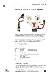
Additional informationThis diagram shows a basic break down of both the <strong>Picaxe</strong> 28X1 and <strong>Picaxe</strong> 18X and pins used.
<strong>Micromouse</strong> Maze Editor (included on the CD supplied)In the Software file open the Maze Editor, start setup to copy files. After installation is complete the program willappear in the programs list. The serial port will default to the one used for the <strong>Picaxe</strong> Programming editor.The <strong>Micromouse</strong> Maze Editor software allows you to create, view and save .MAZ files. To create a maze, open anew maze, then just click to add or remove walls.Features :• Viewing popular maze files.• Create and save .MAZ files or .MAZE files.• Up load a maze from you <strong>Micromouse</strong>.• Export a set maze to your <strong>Micromouse</strong>.After your mouse has been run in a maze, you can view a maze it has stored in the 18x <strong>Picaxe</strong>. With you r<strong>Micromouse</strong> turned on connect the Jack lead to the 18x socket click LISTEN FOR MAZE in the FILE MENUthen press Button “A” on your mouse, the maze your mouse has mapped will be shown. The uploaded maze willshow route arrows from the run-start square, to the target or point the mouse was stopped. This is a very usefultool to ensure your mouse has not missed walls or added phantom ones in, it also allows you to record thecompetition maze for future reference without having to draw it by hand.You can also load a set maze into the <strong>Picaxe</strong> 18x, setting the route your mouse will take helping with setup byallowing manoeuvres to be exactly calibrated without interference from wall straightening. Create a maze thenEXPORT MAZE DATA in the FILE MENU, this can then be copied and pasted into the 18x Maze Solvingprogram, replacing the blank maze.
DIY MICROMOUSE MAZE FOR• LOW COST• EIGHTEEN CELL MAZE• CHANGEABLE LAYOUTThe following instructions demonstrate how to create a low cost <strong>Micromouse</strong> maze.• Wicks Blackboard paint• B&Q Hardboard 1220 x 610 x 3mm• B&Q MDF 1220 x 607 x 12mm• B&Q Cutting MDF into 5 x 5cm stripsPaint the Hardboard with two coats of blackboard paint.Cut the 5 MDF strips as shown using a mitreblock, then lightly sand any rough edges.Cut out twenty-eight small 1.2cm x1.2cm squares out of sticky whitepaper.
Once the black paint is dry use a pencil to draw an 18cm grid as shown.Stick a small white square inthe corner at every point thepencil lines cross.Place your maze blocks sothat the white squares arecovered.These maze walls are only slightlyless reflective than then plasticwalls.
If you are running a non-contactmouse your maze wall do not needto be fixed.Pay a few pounds more and double the maze sizeto 36 cells. Ask for eight 5cm strips to be cut fromyour MDF and buy an additional sheet ofHardboard.With a maze size of 36 cells and your hardboardpositioned as shown. A route to the centre of a fullsize maze (16 x 16 cells) is possible. Remember tomake your 18cm pencil grid go to the edge of thehardboard.
PICone a short history of achievementsPICone is the prototype for the <strong>Picaxe</strong> Maze-solving <strong>Micromouse</strong> featured in this kit. Listedbelow are some great achievements.UK <strong>Micromouse</strong> 07Held on Saturday the 30 th June 2007 at Technology Innovation Centre, Birmingham.PICone was awarded Best Engineered Mouse.Picone was entered into the non-contact wall following class.Although it was still under development it was programmed with a simple routine enabling it to follow awall. But unlike the rest of the wall followers it could track its position and indicate when it had reachedthe centre of the maze.ROBOtic 07Held on Saturday 24 th November 2007 at Technology Innovation Centre, Birmingham.PICone achieved 4 TH place in the Maze-solving Finals.Picone was now able to solve the maze and ran extremely well. Although its final time was quite slowits reliability shone through and stood out as the only maze-solving mouse to complete the final mazewith out incurring a touch penalty.Techfest 08 Asia's Largest Science and Technology FestivalHeld over the last weekend in January 08 at IIT Bombay, India.PICone achieved a time comparable to 2 nd place against student only entries.Once again Picone showed extreme reliability achieving its goal with out any exterior assistance. Thecompetition was only open to students and with over 30 maze-solving mice in the finals <strong>Micromouse</strong> isproving very popular in India. Once the students had ran there mice Picone was ran in the same maze infront of the vast audience and successfully demonstrated simplistic control with a time of 66seconds.Minos 08Held on Sunday 13 th April 2008 at Royal Holloway, University of LondonPICone achieved 4 th place maze-solving finalsCompetition is heating up as new faster mice are on the horizon. Picone still managed a respectable timekeeping it fast enough to set a good bench mark for <strong>Micromouse</strong> without depriving the top prizes fromtrue individual innovation.UK <strong>Micromouse</strong> 08Held on Saturday 28th June 2008 at The Technology Innovation Centre, Birmingham.PICone achieved 4 th place Maze-solving Finals.Steady and reliable PICone achieved a respectable time without incurring a touch penalty, once againremaining out of the top three but proving a simple Basic program running on <strong>Picaxe</strong> processors willachieve success in <strong>Micromouse</strong>.