DayandNight MV Blower Specs.pdf
DayandNight MV Blower Specs.pdf
DayandNight MV Blower Specs.pdf

You also want an ePaper? Increase the reach of your titles
YUMPU automatically turns print PDFs into web optimized ePapers that Google loves.
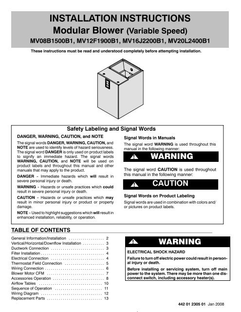
INSTALLATION INSTRUCTIONSModular <strong>Blower</strong> (Variable Speed)<strong>MV</strong>08B1500B1, <strong>MV</strong>12F1900B1, <strong>MV</strong>16J2200B1, <strong>MV</strong>20L2400B1These instructions must be read and understood completely before attempting installation.Safety Labeling and Signal WordsDANGER, WARNING, CAUTION, and NOTEThe signal words DANGER, WARNING, CAUTION, andNOTE are used to identify levels of hazard seriousness.The signal word DANGER is only used on product labelsto signify an immediate hazard. The signal wordsWARNING, CAUTION, and NOTE will be used onproduct labels and throughout this manual and othermanuals that may apply to the product.DANGER -- Immediate hazards which will result insevere personal injury or death.WARNING -- Hazards or unsafe practices which couldresult in severe personal injury or death.CAUTION -- Hazards or unsafe practices which mayresult in minor personal injury or product or propertydamage.NOTE -- Used to highlight suggestions which will result inenhanced installation, reliability, or operation.Signal Words in ManualsThe signal word WARNING is used throughout thismanual in the following manner:WARNING!WARNINGThe signal word CAUTION is used throughoutthis manual in the following manner:!CAUTIONSignal Words on Product LabelingSignal words are used in combination with colors and/or pictures on product labels.TABLE OF CONTENTSGeneral Information/Installation .................. 2Vertical/Horizontal/Downflow Installation ........... 3Ductwork Connection ........................... 3Filter Installation ................................ 4Electrical Connection ........................... 4Thermostat Field Connection .................... 5Wiring Connection .............................. 6<strong>Blower</strong> Motor CFM ............................. 7Accessories Operation .......................... 8Airflow Tables ................................ 10Sequence of Operation ........................ 11Wiring Diagram ............................... 12Replacement Parts ............................ 13! WARNINGELECTRICAL SHOCK HAZARDFailure to turn off electric power could result in personalinjury or death.Before installing or servicing system, turn off mainpower to the system. There may be more than one disconnectswitch, including accessory heater(s).442 01 2305 01 Jan 2008
MODULAR BLOWER: <strong>MV</strong>4. Use field installed vibration isolators in auxiliary drain panto support cabinet.DUCT CONNECTIONSSUPPLY DUCTSupply duct must be attached to the outside of flange on outletend of unit. Flexible connectors may be used if desired. Maintainclearances from supply duct to combustibles when heaters areinstalled. Refer to Figure 1 and unit rating plate.RETURN DUCTReturn duct should be attached to bottom of unit using sheetmetal screws or other fasteners.FILTER INSTALLATIONFilters must be field supplied. A remote filter grille or other meansmust be provided. Refer to ACCA Manual D for remote filtersizing.Figure 5Horizontal InstallationSee NoteBelowFigure 6ABCDEFLOW VOLTAGE TERMINAL BLOCK5AMPFUSEVIOBLUORNBLKSEC1AUX HEAT KW/CFMA B C DINSTALLATION INSTRUCTIONSSEC2AC/HP SIZEA B C DSYSTEM TYPEAC HP -COMFORT HP--EFFAC/HP CFM ADJUSTNOM LOHION/OFF DELAYENHFan Control BoardJ2DhRW1W 2 Y1Y/Y 2GOCWHTCONTINUOUS FANLO MED HI YELAUX1 HUM1YELCEBD430226--01B CESS430226--01BAUX2 HUM230 024VAC90 0HEATER/MOTORGRYJ1J2 JUMPERMOLEX 12--PIN CONNECTORRefrigerantLinesVibrationField-FabricatedIsolatorsDrain PanSupports MUST run parallel with blower cabinetDrainLinesNOTE: If increased structural strength is needed in thehorizontal position, use field supplied connecting plates inplace of the tabs on the bottom of the blower.ELECTRICAL CONNECTIONSThe <strong>MV</strong> modular blower utilizes a variable--speed constant CFMblower motor with an electronic fan control board. The fan controlboard contains a low voltage protective fuse (5 AMP), and pigtailconnections for thermostat hook up. The fan control also containsselection taps to modify airflow operation based uponpre--programmed airflow tables.All electrical work MUST conform with the requirements of localcodes and ordinances and the National Electrical Code NFPA 70current edition.The low voltage transformer and the fan control are standard onall models and are prewired at the factory. Line voltageconnections are made to the heater accessory or the lugs on theNo Heat Kit.OVERCURRENT PROTECTIONThe power supply wiring to the unit MUST be provided withovercurrent protection. Governing codes may require this to befuses ONLY or circuit breakers.For blower cabinets without heaters, a 15 amp circuit may beused.Before proceeding with electrical connections, make certain thatsupply voltage, frequency, phase, and circuit ampacity are asspecified on the unit rating plate. See unit wiring label for properfield high and low voltage wiring. Make all electrical connectionsin accordance with the NEC and any local codes or ordinancesthat may apply. Use copper wire only. The unit must have aseparate branch electric circuit with a field--supplied disconnectswitch located within sight from and readily accessible from theunit.NOTE: When a pull--out type disconnect is removed from the unit,only the Load side of the circuit is de--energized. The Line sideremains live until the main (remote) disconnect is turned off.!ELECTRICAL SHOCK or UNIT DAMAGE HAZARDFailure to follow this warning could result in personalinjury, death, and/or property damage.If a disconnect switch is to be mounted on unit,select a location where drill and fasteners will notcontact electrical refrigeration components.!ELECTRICAL SHOCK or UNIT DAMAGE HAZARDFailure to follow this warning could result in personalinjury, death, and/or property damage.Turn OFF electric power at fuse box or servicepanel before making any electrical connectionsand ensure a proper ground connection is madebefore connecting line voltage.442 01 2305 014
INSTALLATION INSTRUCTIONS!ELECTRICAL SHOCK HAZARDFailure to follow this warning could result in personalinjury or death.Turn off the main (remote) disconnect device beforeworking on incoming (field) wiring. Incoming(field) wiring on the line side of the disconnectfound in the modular blower unit remains live,even when the pull -out is removed. Service andmaintenance to incoming (field) wiring cannot beperformed until the main disconnect switch (remoteto the unit) is turned off.<strong>MV</strong> units installed without electric heat require the use of afactory--authorized No Heat Kit (accessory part numberEHIA00KN10). This kit provides the electrical connectionsnecessary to supply the unit with 208/230V power when electricheat is not present.For units without electric heat:1. Locate adapter and filler plates with screws insidepackage. If necessary, adjust plates to allow forinstallation of No Heat Kit required inside cabinet. Referto Figure 7.2. Secure No Heat Kit accessory with four (4) screws.3. Connect the 9--pin plug from No Heat Kit wiring into thereceptacle that attaches to fan control board.4. Connect ground wire to unit ground lug.5. Connect 208/230V power leads from field disconnect toterminal block assembly on No Heat Kit.For units with electric heat, see Electric Heater InstallationInstructions and blower airflow requirements.NOTE: Transformer is factory--wired for 230V operation. For208V applications the transformer must be rewired to the 208Vtap. Refer to unit wiring label.GROUNDING CONNECTIONUse a copper conductor(s) from the ground lug on the No Heat Kitor ground lugs on the electric heater to a grounded connection inthe electric service panel or a properly installed grounding rod.LOW VOLTAGE CONTROL CONNECTIONSWire low--voltage in accordance with wiring label on the blower(refer to Figures 8 - 11). Use 18 AWG color--coded, insulated(35°C minimum) wire to make the low--voltage connectionsbetween: thermostat, indoor equipment, and outdoor equipment.If thermostat is located more than 100 feet from the unit (asmeasured along the low voltage wire), use 16 AWG color--coded,insulated (35°C minimum) wire. All wiring must be NEC Class 1and must be separated from incoming power leads. Refer tooutdoor unit wiring instructions for additional wiringrecommendations.MODULAR BLOWER: <strong>MV</strong>Field supplied low--voltage wiring should be field connectedinside control splice box area (secure with wire nuts), and strainrelief bushing or rubber grommet to seal cabinet opening.Fan control board is circuited for single--stage heater operation.When additional heater staging is desired (using indoor wallthermostat or ODTS), remove the Jumper J2 on fan control boardto enable staging.THERMOSTAT FIELD CONNECTIONSDh Dh is used if additional latent capacity control is required(see Dehumidification Capability in the Accessoriessection for more detail). NOTE: the J1 jumper shouldalready be removed from the factory.R R signal is 24V hot to thermostatW1 W1 signal controls electric heat from the thermostatW2 W2 signal from a two--stage thermostat or outdoorthermostatY1 Connection for the low speed compressor operationY/Y2 Connection for the Y signal or high speed (Y2) signalfrom the thermostatG Connection for the G (fan) signal is energized from thethermostat, ’HUM2’ and AUX2’ terminals are energizedwhen G energizedO Connection for the ’O’ signal from the thermostatC Connection for the C terminal to the thermostat (24Vcommon) also common to SEC1, HUM1, AUX1Figure 7Low VoltageConnectionsFiller PlateAdapter PlateNo Heat KitElectrical ControlsTransformerLugs forLine Voltageand GroundConnectionsControl Splice BoxTable 1Supply CircuitVolts Phase HertzSupplyCircuitNo.H.P.Max.MotorAmpsMCABranchCircuitAMPMax Over -currentProtectionDevise(Amps)#ofWiresRecommendedSupply Wire75°C copperGround Wire5 442 01 2305 01MinSizeMax. Ft.Length#ofWires<strong>MV</strong>08*2082301 60 Single 1/2 5.0 6.3 15 2 14 118 1 14<strong>MV</strong>12*2082301 60 Single 1/2 5.0 6.3 15 2 14 118 1 14<strong>MV</strong>16*2082301 60 Single 3/4 7.3 9.1 15 2 14 82 1 14<strong>MV</strong>20*2082301 60 Single 3/4 7.3 9.1 15 2 14 82 1 14* Modular blower without electric heat Conversion: 1 ft = .305 meterMinSize
INSTALLATION INSTRUCTIONSBLOWER MOTOR - CFMFAN CONTROL BOARD CONFIGURATIONThe Fan Control Board can be configured by the installer andshould be operated within its specified CFM range (refer to Table2). The ECM motor uses wire selection taps (A through F) tomodify operation determined from a pre--programmed airflowtable (refer to Figure 6 for wire selection and tap indentification,and Tables 4 and 5 for airflows). Airflows are based on systemsize and/or mode of operation. These airflows are automaticallymodified as needed in response to other inputs such as the needfor dehumidification, etc.Table 2<strong>MV</strong> Modular CFM RangeModular Unit Size Outdoor Unit Size CFM Range018024<strong>MV</strong>08350 - 1200030036024030<strong>MV</strong>12415 - 1400036042030036<strong>MV</strong>16425 - 1600042048036042<strong>MV</strong>20540 - 2000048060The Modular <strong>MV</strong> unit must be configured to operate properly withall of the system components that have been installed. Tosuccessfully configure a basic system, move the wire selectiontap (as needed) to the proper pin position.NOTE: The factory default setting for all selections is the first pin.It is recommended the installer review each setting (see belowand refer to Figure 6 for wire selection and tap indentification).A. AUXILIARY HEAT KW/CFM (VIOLET WIRE)Select the CFM range based on the electric heater kW size byusing the Violet wire.If no heater is installed, this step can be skipped. However, whenan electric heater is applied, move the Violet wire to the proper A,B, C, D pin selection. Refer to Table 6 for heater range selection.The heater kW ranges corresponds directly to each pin letterlisted in the table.The airflow must be greater than the minimum CFM for electricheater application with the size system installed for safe andcontinuous operation. (refer to Tables 4 and 5 for airflow).NOTE: Airflow marked is the airflow which will be supplied inemergency heat mode and heating mode on air conditionerswhen electric heat is the primary heating source.In heat pump heating mode when electric heaters are energized,the ECM motor will run the higher or heat pump heating airflowand electric heater airflow to ensure safe heater operation. Thefactory selection is the largest heater range approved.B. OUTDOOR UNIT SIZE (BLUE WIRE)Select the outdoor unit system size (BTU) by using the Blue wire(refer to Table 7).The installer needs to properly select the outdoor unit size toensure proper airflow delivery of the modular unit. This selectionaffects all operational modes (airflow) with the exception ofelectric heat modes.MODULAR BLOWER: <strong>MV</strong>Move the Blue wire to the proper A, B, C, D pin selection. Theoutdoor unit size corresponding directly to each pin letter is listedin Table 7.C. SYSTEM TYPE - AC/HP (ORANGE WIRE)Select the system type (AC, HP--Comfort, HP--Efficiency) byusing the Orange wire.S AC -- Air Conditioner selection provides approximately 350CFM per ton for greater efficiency and humidity control withthe AC/HP CFM ADJUST set to the nominal (NOM) tap. (Toachieve approximately 400 CFM per ton move tap to (HI)position. Refer to appropriate airflow tables for exact CFMsetting.)S HP -COMFORT -- Heat Pump Comfort selection providesapproximately 315 CFM per ton for higher than normalheating air delivery temperature. Provides approximately350 CFM per ton cooling airflow for good humidity removalwith the AC/HP CFM ADJUST set to the nominal (NOM)tap.S HP -EFF -- Heat Pump Efficiency selection provides sameairflow for heating and cooling modes to increase overallHP efficiency; approximately 350 CFM per ton with theAC/HP CFM ADJUST set to the nominal (NOM) tap.D. AC/HP CFM ADJUSTSelect the system AC/HP CFM Adjust by using the Black wire.This selection basically selects; Medium, Low, or High AirflowS NOM -- provides airflow at rates described above, theAC/HP ADJUST select is factory set to the nominal (NOM)tap. The adjust selections HI/LO will regulate airflowsupplied for all operational modes, except non--heat pumpheating modes.S HI -- provides 15% airflow over nominal unit size selectedS LO -- provides 10% airflow below nominal unit sizeselected.Adjust selection options are provided to adjust airflow supplied tomeet individual installation needs for such things as noise,comfort, and humidity removal.E. ON/OFF DELAYSelect the ON/OFF delay by using the White wire. This selectionbasically selects the desired time delay profile.NOTE: Delay selections are active in cooling and heat pumpheating modes only. Auxiliary heating modes have a one (1)minute off delay and zero (0) on delay programmed into the ECMmotor that cannot be overridden.Choose one (1) of four (4) motor operation delays to customizeand enhance system operation as follows.Selection options are:1. 0/90: 0 (zero) second on--delay and 90 second off--delay at100% airflow (factory setting).2. 30/90: 30 second on--delay with no airflow and 90 secondoff--delay at 100% airflow profile. Used when it is desirableto allow system coils time to heat--up/cool--down inconjunction with the airflow.3. 0/0: 0 (zero) second on--delay option and 0 (zero) secondoff--delay. Used for servicing unit or when a thermostat isutilized to perform delay functions.4. ENH: Enhanced selection provides a 30 second on--delaywith no airflow followed by 150 seconds at 70% airflow, and0 (zero) second off--delay for added comfort. This profilewill minimize cold blow in heat pump operation and couldenhance system efficiency.F. CONTINUOUS FANSelect the desired Continuous fan speed when thermostat is seton continuous fan operation by using the Yellow jumper wire.7 442 01 2305 01
MODULAR BLOWER: <strong>MV</strong>NOTE: If installed with a two--stage outdoor unit, do not select HIspeed continuous fan. If HI is selected, low stage compression(low--speed cooling) will also run HI fan speed possibly resultingin insufficient dehumidification.1. LO speed -- factory setting, approximately 50% coolingmode airflow.2. MED speed -- move connector to MED, approximately 65%cooling mode airflow.3. HI speed -- move connector to HI, approximately 100%cooling mode airflow.G. LOW -VOLTAGE CIRCUIT(FUSING AND REFERENCE)The low--voltage circuit is fused by a board--mounted 5--ampautomotive fuse placed in series with the transformer SEC2 andthe R circuit. The C circuit of the transformer is referenced tochassis ground through a printed circuit run at SEC1 connected tometal standoff marked with ground symbol.H. QUICK SET UP(BASIC MODULAR BLOWER CONFIGURATION)The following basic configuration of the modular blower willprovide ARI rated performance of an Air Conditioner:1. AUX HEAT KW/CFM -- Select the heater range for the sizeelectric heater installed.2. OUTDOOR UNIT SIZE -- Select system size installed.3. SYSTEM TYPE -- Select system type AC.4. AC/HP CFM ADJUST -- Select NOM.5. ON/OFF DELAY -- Select 0/90 profile.6. CONTINUOUS FAN -- Select desired modular blowerwhen thermostat is set to continuous fan.The following basic configuration of the modular blower willprovide ARI rated performance of a Heat Pump:1. AUX HEAT KW/CFM -- Select the heater range for the sizeelectric heater installed.2. OUTDOOR UNIT SIZE -- Select system size installed.3. SYSTEM TYPE -- Select system type HP--EFF.4. AC/HP CFM ADJUST -- Select NOM.5. ON/OFF DELAY -- Select 0/90 profile.6. CONTINUOUS FAN -- Select desired fan speed whenthermostat is set to continuous fan.ACCESSORIESAUXILIARY TERMINALSThe Fan Control Board contains the following auxiliary terminals,refer to Figure 6.HUM1 and AUX1 are in common with SEC1, and thermostatcommon.HUM2 and AUX2 terminals are tied directly to the G terminal fromthermostat, and provide a 24 VAC hot signal whenever the Gterminal is energized.HUMIDIFIER OPERATION WITHHUMIDISTATA standard humidistat can be used to operate a humidifier. TheHUM1 is internally connected to 24V Common (C), and HUM2 isinternally connected to (G). Refer to Figure 12 for typicalHumidifier wiring layout using HUM1 (C), and HUM2 (G).Alternately, the 24VAC signal may also be sourced from the W1and Com (thermostat pigtail) connections when electric heatersare used as a primary heating source (refer to Figure 13).NOTE: When using a thermostat with built--in humidity control,the above auxiliary terminals can be ignored, and the humidifiermay be sourced directly from humidity terminals located on thethermostat itself. (Refer to Figures 8 - 11)INSTALLATION INSTRUCTIONSDEHUMIDIFY CAPABILITYThe J1 jumper should always be removed from the Fan ControlBoard for proper airflow operation.Latent capacities for systems using the <strong>MV</strong> are better thanaverage systems. If increased latent capacity is an applicationrequirement, the field wiring (thermostat pigtail) connectionsprovides a (Dh) for use with a standard humidity sensor/control(Refer to Figure 14 for additional latent control). The <strong>MV</strong> willdetect a closed contact between R and Dh (closing on a humidityrise) and reduce its airflow to approximately 80% of nominalcooling mode airflow. This reduction will increase the systemlatent capacity until the humidity falls to a level which causes thehumidity sensor/control to open its contacts.When the contacts open, the airflow will return to 100% of theselected cooling airflow. Refer to Figure 15 for Normal AirflowOperation.Figure 12HUM 1(C)HUM 2(G)Figure 13(TERMINAL BOARDCONNECTIONS)CommW1Figure 1424--VAC24--VACRFigure 15RHumidifyHumidifier WiringHUMIDISTATTO HUMIDIFIERHumidifier Wiring for Electric HeatPrimary Heating SourceHUMIDISTATTO HUMIDIFIERDe -HumidifyAdditional Latent ControlDh24--VACcloseNormal Airflow Operation24--VACopenHEATER STAGINGThe <strong>MV</strong> modular fan control board is factory set for single--stageelectric heat operation. Refer to Table 3 for available heaters.When two--stage electric heat is desired, the J2 jumper must beremoved. Refer to Table 3 -2 for two--stage compatible heaters.Removing J2 will allow second stage control by the indoor wallthermostat (if multi--stage capable), or by using an accessoryODTS (outdoor thermostat temperature switch). Refer to ODTSkit instruction for wiring information (AMF002OTA1).When three--stage electric heat is desired, the J2 jumper must beremoved. Refer to Table 3 -3 for three--stage compatible heaters.Removing J2 will allow second--stage control by the indoor wallthermostat (if multi--stage capable), and the third--stage by usingan accessory ODTS. Refer to ODTS kit instruction for wiringinformation.Dh442 01 2305 018
INSTALLATION INSTRUCTIONSMODULAR BLOWER: <strong>MV</strong>Table 3Single--PhaseThree--PhaseHeat Strip Staging3-1 3-2 3-3Single--StageOperationTwo--StageCapable(no staging -- allelectric heattogether)Three--StageCapable(with ODTSonly)EHIA05KB / KN EHIA15KB EHIA25KBEHIA07KB / KN EHIA20KBEHIA10KB / KN EHIA25KBEHIA15KBEHIA20KBEHIA25KBEHIA10HB EHIA10HB EHIA20HBEHIA15HB EHIA15HB EHIA25HBEHIA20HB EHIA20HBEHIA25HB EHIA25HBKB is single--phase with circuit breakerKN is single--phase with terminal block (no--breaker)HB is three--phase with circuit breakerAIR FLOW CHECKFor proper system operation, the air flow through the indoor coilshould be between 350 and 450 CFM per ton of cooling capacity.The air flow through the unit can be determined by measuring theexternal static pressure to the unit and selecting the motor speedtap that will most closely provide the required air flow.1. Set up to measure external static pressure at the supplyand return duct connections. Refer to Figure 16.2. Drill holes in the ducts for pressure taps, pilot tubes, orother accurate pressure sensing devices.3. Connect these taps to a level inclined manometer or draftgauge.4. Ensure the coil and filter are clean, and all the registers areopen.5. Determine the external static pressure with the bloweroperating.6. Refer to the Air Flow Data, Table 4, to find the speed settingthat will most closely provide the required air flow for thesystem.7. Refer to Motor Speeds and Airflow in these instructions ifthe speed is to be changed.8. Recheck the external static pressure with the new setting,and confirm speed switch selection.Figure 16Static Pressure CheckSupplyIndoorSectionInclineManometerReturnTEMPERATURE RISE CHECKTemperature rise is the difference between the supply and returnair temperatures.NOTE: The temperature rise can be adjusted by changing theheating speed tap at the fan control board. Refer to the unit’sInstallation Instructions for airflow information.A temperature rise greater than 60°F (33.3°C) is notrecommended.1. To check the temperature rise through the unit, placethermometers in the supply and return air ducts as close tothe unit as possible,avoiding direct radiant heat from theheater elements.2. Open ALL registers and duct dampers.3. Set thermostat Heat--Cool selector to HEAT.4. Set the thermostat temperature setting as high as it will go.5. Turn electric power ON.6. Operate unit AT LEAST 5 minutes, then checktemperature rise.NOTE: The maximum outlet air temperature for all models is200°F (93.3°C).7. Set thermostat to normal temperature setting.8. Be sure to seal all holes in ducts if any were created duringthis process.9 442 01 2305 01
MODULAR BLOWER: <strong>MV</strong>INSTALLATION INSTRUCTIONSTable 4ModularUnit Size<strong>MV</strong>08<strong>MV</strong>12<strong>MV</strong>16<strong>MV</strong>20Modular Airflow Delivery (CFM) in Cooling Mode (either A/C or HP)Single--Stage A/CTwo--Stage CoolingOutdoorFan OnlyCooling A/C Cooling -- High A/C Cooling -- LowUnit SizeNominal Dehum Nominal Dehum Nominal Dehum LOW MED HI18 525 420 -- -- -- -- -- -- -- -- 350 420 52524 700 560 700 560 560 450 350 560 70030 875 700 -- -- -- -- -- -- -- -- 440 700 87536 1050 840 1050 840 840 670 525 840 105024 700 560 700 560 560 450 415 560 70030 875 700 -- -- -- -- -- -- -- -- 440 700 87536 1050 840 1050 840 840 670 525 840 105042 1225 980 -- -- -- -- -- -- -- -- 615 980 122530 875 700 -- -- -- -- -- -- -- -- 440 700 87536 1050 840 1050 840 840 670 525 840 105042 1225 980 -- -- -- -- -- -- -- -- 615 980 122548 1400 1120 1400 1120 1120 900 700 1120 140036 1050 840 1050 840 840 670 540 840 105042 1225 980 -- -- -- -- -- -- -- -- 615 980 122548 1400 1120 1400 1120 1120 900 700 1120 140060 1750 1400 1750 1400 1400 1120 875 1400 1750NOTES:1. The above airflows result with the AC/HP CFM ADJUST select jumper set on NOM.2. Airflow can be adjusted +15% or --10% by selecting Hi or Lo respectively for all modes except fan only.3. Dry coil at 230 volts and with 10kW heater and filter installed.4. Airflows shown are valid for systems with total static pressure between 0.1 and 0.7 in wc.Table 5ModularUnit Size<strong>MV</strong>08<strong>MV</strong>12<strong>MV</strong>16<strong>MV</strong>20Modular Airflow Delivery (CFM) in Heat Pump Heating Mode OnlySingle--Stage HPTwo--Stage HeatingOutdoorFan OnlyHeatingHP Heating -- High HP Heating -- LowUnit SizeComfort Eff Comfort Eff Comfort Eff Low Med Hi18 475 525 -- -- -- -- -- -- -- -- 350 380 47524 630 700 630 700 505 560 350 505 63030 785 875 -- -- -- -- -- -- -- -- 440 630 78536 945 1050 945 1050 755 840 525 755 94524 630 700 630 700 505 560 415 505 63030 785 875 -- -- -- -- -- -- -- -- 440 630 78536 945 1050 945 1050 755 840 525 755 94542 1100 1225 -- -- -- -- -- -- -- -- 615 880 110030 785 875 -- -- -- -- -- -- -- -- 440 630 78536 945 1050 945 1050 755 840 525 755 94542 1100 1225 -- -- -- -- -- -- -- -- 615 880 110048 1260 1400 1260 1400 1010 1120 700 1010 126036 945 1050 945 1050 755 840 540 755 94542 1100 1225 -- -- -- -- -- -- -- -- 615 880 110048 1260 1400 1260 1400 1010 1120 700 1010 126060 1575 1750 1575 1750 1260 1400 875 1260 1575NOTES:1. The above airflows result with the AC/HP CFM ADJUST select jumper set on NOM.2. Airflow can be adjusted +15% or --10% by selecting Hi or Lo respectively for all modes except fan only.3. Dry coil at 230 volts and with 10kW heater and filter installed.4. Airflows shown are valid for systems with total static pressure between 0.1 and 0.7 in wc.Table 6Airflow Adjust TableTable 7Outdoor Unit SizeMODEL # AUX HEAT RANGE (KW/CFM)MODEL #OUTDOOR UNIT SIZE (BTU)VIOLETWire A B C DSelection<strong>MV</strong>08 15kw -- -- 10kw 5thru7.5kw<strong>MV</strong>12 -- -- 15 thru 20kw 10kw 5thru7.5kw<strong>MV</strong>16 -- -- 25kw -- -- 5 thru 20kw<strong>MV</strong>20 -- -- -- -- 25kw 5 thru 20kwBLUE WireSelectionA B C D<strong>MV</strong>08 036 030 024 018<strong>MV</strong>12 042 036 030 024<strong>MV</strong>16 048 042 036 030<strong>MV</strong>20 060 048 042 036442 01 2305 0110
INSTALLATION INSTRUCTIONSMODULAR BLOWER: <strong>MV</strong>SEQUENCE OF OPERATION<strong>MV</strong> modular blower will supply airflow in a range which is morethan twice the range of a standard modular blower. Each modularblower size is designed to provide nominal cooling capacities at50 _F evaporator temperature and the required airflow in order tomatch with any of four (4) different air conditioner or heat pumpoutdoor unit sizes. Table 2 outline the CFM range for the different<strong>MV</strong> modular blowers.The blower motor is a true variable speed motor designed todeliver constant CFM. Constant CFM is valid for systems withtotal external static pressure between 0.1 and 0.7 inches watercolumn.A.. CONTINUOUS FANS Thermostat closes circuit R to G.S<strong>Blower</strong> runs at continuous fan airflow.B. COOLING MODE - SINGLE STAGESNOTE:SIf indoor temperature is above temperature set point andhumidity is below humidity set point, thermostat closescircuits R to G, R to Y/Y2 and R to O.For single stage systems, do not use the Y1terminal.Modular blower delivers single stage cooling airflow.C. COOLING MODE - TWO STAGESSSSFirst stage (low) cooling: Thermostat closes circuits to R toG, R to O, and R to Y1.Modular blower delivers low stage cooling airflow.Second stage (high) cooling: Thermostat closes circuits toRtoG,RtoO,RtoY1andRtoY/Y2.Modular blower delivers high stage cooling airflow.D. ELECTRIC HEAT HEATING MODES Thermostat closes circuit R to W/W1, or W2.SModular blower delivers the selected electric heat airflow.E. HEAT PUMP HEATING MODE - SINGLE STAGESNOTE:Thermostat closes circuits R to G and R to Y/Y2.For single stage systems, do not use the Y1terminal.S Modular blower delivers single stage heat pump heatingairflow.F. HEAT PUMP HEATING MODE - TWO STAGESFirst stage (low) heating: Thermostat closes circuits R to Gand R to Y1.If the thermostat calls for electric heat when the heat pump isoperating in heating or defrost, the motor will modify the airflow ifnecessary. The motor will provide an airflow which is safe for theoperation of the electric heat. That airflow is the greater of the heatpump heating airflow and the electric heat only airflow.! CAUTIONELECTRICAL SHOCK or UNIT DAMAGE HAZARDFailure to carefully read and follow this CAUTIONwarning could result in equipment malfunction,property damage, personal injury and/or death.Disconnect power to unit before removing or replacingconnectors or servicing motor. Wait at least five(5) minutes after disconnecting power before openingmotor.CARE AND MAINTENANCEThe system should be regularly inspected by a qualified servicetechnician. Consult the servicing dealer for recommendedfrequency. Between visits, the only consumer servicerecommended or required is air filter maintenance andcondensate drain operation.AIR FILTERInspect air filters at least monthly and replace or clean asrequired. Disposable type filters should be replaced. Reusabletype filters may be cleaned by soaking in mild detergent andrinsing with cold water. The frequency of cleaning depends uponthe hours of operation and the local atmospheric conditions.Install filters with the arrows on the side pointing in the directionof air flow. Clean filters keep unit efficiency high.LUBRICATIONThe bearings of the blower motor are permanently lubricated.CONDENSATE DRAINSDuring the cooling season check the condensate drain lines to besure that condensate is flowing from the primary drain but notfrom the secondary drain. If condensate ever flows from thesecondary drain, the unit should be promptly shut off and thecondensate pan and drains cleaned to insure a free flowingprimary drain.SSModular blower delivers low stage heating airflow.Second stage (high) heating: Thermostat closes R to G, Rto Y1 and R to Y/Y2.SModular blower delivers high stage heating airflow.G. HEAT PUMP HEATING WITH AUXILIARY ELECTRICHEATSThermostat closes circuits R to G, R to Y/Y2 and/or R to Y1withRtoW/W1orW2(andRtoOinthecaseofdefrost).11 442 01 2305 01
MODULAR BLOWER: <strong>MV</strong>INSTALLATION INSTRUCTIONSFigure 17Wiring Diagram22442 01 2305 0112
INSTALLATION INSTRUCTIONSMODULAR BLOWER: <strong>MV</strong>Replacement PartsKEYNO.DESCRIPTIONPART NUMBER<strong>MV</strong>08B1500B1<strong>MV</strong>12F1900B1<strong>MV</strong>16J2200B1<strong>MV</strong>20L2400B1KEYNO.DESCRIPTIONPART NUMBER<strong>MV</strong>08B1500B1<strong>MV</strong>12F1900B1<strong>MV</strong>16J2200B1<strong>MV</strong>20L2400B11 Board, Fan Control 1175186 1 1 1 12 Transformer 208/230>24V 40VA 1082611 1 1 1 13 Motor, <strong>Blower</strong> 1/2--hp VSP 1172828 1 1 -- --3/4--hp VSP 1172829 -- -- 1 14 Motor Mount Arm 4.5” (Kit) 1057955 1 1 1 15 Wheel, <strong>Blower</strong> DD10x7x1/2 CW CV 600586 1 -- -- --DD10x8x1/2 CW CV 600587 -- 1 -- --DD10x9x1/2 CW CV 96839 -- -- 1 16 Motor, Control Module 1176288 1 -- -- --1176289 -- 1 -- --1176290 -- -- 1 --1176291 -- -- -- 1B Door, <strong>Blower</strong> 1176308 1 -- -- --1176309 -- 1 -- --1176310 -- -- 1 --1176311 -- -- -- 1C Plate, Heater Adapter 1084606 -- 1 1 1D Plate, Heater Filler 1084608 -- -- 1 1E Panel, Back Wrapper 1176312 1 -- -- --1176313 -- 1 -- --1176314 -- -- 1 --1176315 -- -- -- 1F Panel, L.H. Side Wrapper 1176316 1 1 1 1G Panel, R.H. Side Wrapper 1176317 1 1 1 1H Low Voltage Barrier 1176335 1 1 1 1J Brace, Bottom Front 1069603 1 -- -- --1069604 -- 1 -- --1069605 -- -- 1 --1087670 -- -- -- 1Replacement Parts Expanded ViewK Panel, Rear <strong>Blower</strong> Deck 1176318 1 -- -- --1176319 -- 1 -- --1176320 -- -- 1 --1176321 -- -- -- 1L Panel, Front <strong>Blower</strong> Deck 1176322 1 -- -- --1176323 -- 1 -- --1176324 -- -- 1 --1176325 -- -- -- 1M Panel, Side <strong>Blower</strong> Deck 1176326 2 -- -- --1176327 -- 2 -- --1176328 -- -- 2 --1176329 -- -- -- 2P Panel, Top 1176330 1 -- -- --1176331 -- 1 -- --1176332 -- -- 1 --1176333 -- -- -- 1Q <strong>Blower</strong> Housing Assy DD10--7A 1176353 1 -- -- --DD10--8A 1176354 -- 1 -- --DD10--9A 1176355 -- -- 1 1R Panel, Cutoff 1082607 1 -- -- --1082616 -- 1 -- --1082949 -- -- 1 1S Rail, <strong>Blower</strong> R.H. 1085504 1 1 1 1T Rail, <strong>Blower</strong> L.H. 1085521 1 1 1 1][ PARTS NOT SHOWN][ Harness, Wire (main) 1089053 1 1 1 1][ Harness, Wire (low voltage) 1089054 1 1 1 1][ Bracket, Control Mounting 1176334 1 1 1 1][ Manual, Installation 44201230501 1 1 1 1][ Warranty Certificate 40106403004 1 1 1 11 2PDMCKFEBLSHRTGQ5J3&6413 442 01 2305 01