DayandNight MV Blower Specs.pdf
DayandNight MV Blower Specs.pdf
DayandNight MV Blower Specs.pdf

Create successful ePaper yourself
Turn your PDF publications into a flip-book with our unique Google optimized e-Paper software.
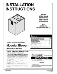
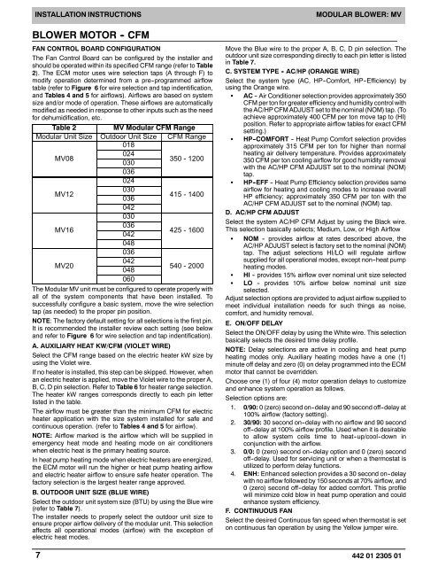
INSTALLATION INSTRUCTIONSBLOWER MOTOR - CFMFAN CONTROL BOARD CONFIGURATIONThe Fan Control Board can be configured by the installer andshould be operated within its specified CFM range (refer to Table2). The ECM motor uses wire selection taps (A through F) tomodify operation determined from a pre--programmed airflowtable (refer to Figure 6 for wire selection and tap indentification,and Tables 4 and 5 for airflows). Airflows are based on systemsize and/or mode of operation. These airflows are automaticallymodified as needed in response to other inputs such as the needfor dehumidification, etc.Table 2<strong>MV</strong> Modular CFM RangeModular Unit Size Outdoor Unit Size CFM Range018024<strong>MV</strong>08350 - 1200030036024030<strong>MV</strong>12415 - 1400036042030036<strong>MV</strong>16425 - 1600042048036042<strong>MV</strong>20540 - 2000048060The Modular <strong>MV</strong> unit must be configured to operate properly withall of the system components that have been installed. Tosuccessfully configure a basic system, move the wire selectiontap (as needed) to the proper pin position.NOTE: The factory default setting for all selections is the first pin.It is recommended the installer review each setting (see belowand refer to Figure 6 for wire selection and tap indentification).A. AUXILIARY HEAT KW/CFM (VIOLET WIRE)Select the CFM range based on the electric heater kW size byusing the Violet wire.If no heater is installed, this step can be skipped. However, whenan electric heater is applied, move the Violet wire to the proper A,B, C, D pin selection. Refer to Table 6 for heater range selection.The heater kW ranges corresponds directly to each pin letterlisted in the table.The airflow must be greater than the minimum CFM for electricheater application with the size system installed for safe andcontinuous operation. (refer to Tables 4 and 5 for airflow).NOTE: Airflow marked is the airflow which will be supplied inemergency heat mode and heating mode on air conditionerswhen electric heat is the primary heating source.In heat pump heating mode when electric heaters are energized,the ECM motor will run the higher or heat pump heating airflowand electric heater airflow to ensure safe heater operation. Thefactory selection is the largest heater range approved.B. OUTDOOR UNIT SIZE (BLUE WIRE)Select the outdoor unit system size (BTU) by using the Blue wire(refer to Table 7).The installer needs to properly select the outdoor unit size toensure proper airflow delivery of the modular unit. This selectionaffects all operational modes (airflow) with the exception ofelectric heat modes.MODULAR BLOWER: <strong>MV</strong>Move the Blue wire to the proper A, B, C, D pin selection. Theoutdoor unit size corresponding directly to each pin letter is listedin Table 7.C. SYSTEM TYPE - AC/HP (ORANGE WIRE)Select the system type (AC, HP--Comfort, HP--Efficiency) byusing the Orange wire.S AC -- Air Conditioner selection provides approximately 350CFM per ton for greater efficiency and humidity control withthe AC/HP CFM ADJUST set to the nominal (NOM) tap. (Toachieve approximately 400 CFM per ton move tap to (HI)position. Refer to appropriate airflow tables for exact CFMsetting.)S HP -COMFORT -- Heat Pump Comfort selection providesapproximately 315 CFM per ton for higher than normalheating air delivery temperature. Provides approximately350 CFM per ton cooling airflow for good humidity removalwith the AC/HP CFM ADJUST set to the nominal (NOM)tap.S HP -EFF -- Heat Pump Efficiency selection provides sameairflow for heating and cooling modes to increase overallHP efficiency; approximately 350 CFM per ton with theAC/HP CFM ADJUST set to the nominal (NOM) tap.D. AC/HP CFM ADJUSTSelect the system AC/HP CFM Adjust by using the Black wire.This selection basically selects; Medium, Low, or High AirflowS NOM -- provides airflow at rates described above, theAC/HP ADJUST select is factory set to the nominal (NOM)tap. The adjust selections HI/LO will regulate airflowsupplied for all operational modes, except non--heat pumpheating modes.S HI -- provides 15% airflow over nominal unit size selectedS LO -- provides 10% airflow below nominal unit sizeselected.Adjust selection options are provided to adjust airflow supplied tomeet individual installation needs for such things as noise,comfort, and humidity removal.E. ON/OFF DELAYSelect the ON/OFF delay by using the White wire. This selectionbasically selects the desired time delay profile.NOTE: Delay selections are active in cooling and heat pumpheating modes only. Auxiliary heating modes have a one (1)minute off delay and zero (0) on delay programmed into the ECMmotor that cannot be overridden.Choose one (1) of four (4) motor operation delays to customizeand enhance system operation as follows.Selection options are:1. 0/90: 0 (zero) second on--delay and 90 second off--delay at100% airflow (factory setting).2. 30/90: 30 second on--delay with no airflow and 90 secondoff--delay at 100% airflow profile. Used when it is desirableto allow system coils time to heat--up/cool--down inconjunction with the airflow.3. 0/0: 0 (zero) second on--delay option and 0 (zero) secondoff--delay. Used for servicing unit or when a thermostat isutilized to perform delay functions.4. ENH: Enhanced selection provides a 30 second on--delaywith no airflow followed by 150 seconds at 70% airflow, and0 (zero) second off--delay for added comfort. This profilewill minimize cold blow in heat pump operation and couldenhance system efficiency.F. CONTINUOUS FANSelect the desired Continuous fan speed when thermostat is seton continuous fan operation by using the Yellow jumper wire.7 442 01 2305 01