DayandNight MV Blower Specs.pdf
DayandNight MV Blower Specs.pdf
DayandNight MV Blower Specs.pdf

You also want an ePaper? Increase the reach of your titles
YUMPU automatically turns print PDFs into web optimized ePapers that Google loves.
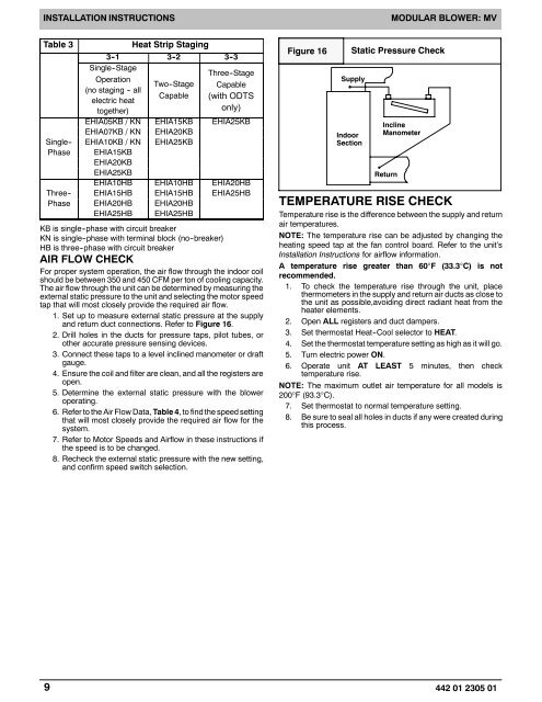
INSTALLATION INSTRUCTIONSMODULAR BLOWER: <strong>MV</strong>Table 3Single--PhaseThree--PhaseHeat Strip Staging3-1 3-2 3-3Single--StageOperationTwo--StageCapable(no staging -- allelectric heattogether)Three--StageCapable(with ODTSonly)EHIA05KB / KN EHIA15KB EHIA25KBEHIA07KB / KN EHIA20KBEHIA10KB / KN EHIA25KBEHIA15KBEHIA20KBEHIA25KBEHIA10HB EHIA10HB EHIA20HBEHIA15HB EHIA15HB EHIA25HBEHIA20HB EHIA20HBEHIA25HB EHIA25HBKB is single--phase with circuit breakerKN is single--phase with terminal block (no--breaker)HB is three--phase with circuit breakerAIR FLOW CHECKFor proper system operation, the air flow through the indoor coilshould be between 350 and 450 CFM per ton of cooling capacity.The air flow through the unit can be determined by measuring theexternal static pressure to the unit and selecting the motor speedtap that will most closely provide the required air flow.1. Set up to measure external static pressure at the supplyand return duct connections. Refer to Figure 16.2. Drill holes in the ducts for pressure taps, pilot tubes, orother accurate pressure sensing devices.3. Connect these taps to a level inclined manometer or draftgauge.4. Ensure the coil and filter are clean, and all the registers areopen.5. Determine the external static pressure with the bloweroperating.6. Refer to the Air Flow Data, Table 4, to find the speed settingthat will most closely provide the required air flow for thesystem.7. Refer to Motor Speeds and Airflow in these instructions ifthe speed is to be changed.8. Recheck the external static pressure with the new setting,and confirm speed switch selection.Figure 16Static Pressure CheckSupplyIndoorSectionInclineManometerReturnTEMPERATURE RISE CHECKTemperature rise is the difference between the supply and returnair temperatures.NOTE: The temperature rise can be adjusted by changing theheating speed tap at the fan control board. Refer to the unit’sInstallation Instructions for airflow information.A temperature rise greater than 60°F (33.3°C) is notrecommended.1. To check the temperature rise through the unit, placethermometers in the supply and return air ducts as close tothe unit as possible,avoiding direct radiant heat from theheater elements.2. Open ALL registers and duct dampers.3. Set thermostat Heat--Cool selector to HEAT.4. Set the thermostat temperature setting as high as it will go.5. Turn electric power ON.6. Operate unit AT LEAST 5 minutes, then checktemperature rise.NOTE: The maximum outlet air temperature for all models is200°F (93.3°C).7. Set thermostat to normal temperature setting.8. Be sure to seal all holes in ducts if any were created duringthis process.9 442 01 2305 01