DayandNight MV Blower Specs.pdf
DayandNight MV Blower Specs.pdf
DayandNight MV Blower Specs.pdf

Create successful ePaper yourself
Turn your PDF publications into a flip-book with our unique Google optimized e-Paper software.
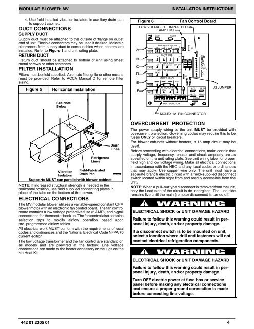
MODULAR BLOWER: <strong>MV</strong>4. Use field installed vibration isolators in auxiliary drain panto support cabinet.DUCT CONNECTIONSSUPPLY DUCTSupply duct must be attached to the outside of flange on outletend of unit. Flexible connectors may be used if desired. Maintainclearances from supply duct to combustibles when heaters areinstalled. Refer to Figure 1 and unit rating plate.RETURN DUCTReturn duct should be attached to bottom of unit using sheetmetal screws or other fasteners.FILTER INSTALLATIONFilters must be field supplied. A remote filter grille or other meansmust be provided. Refer to ACCA Manual D for remote filtersizing.Figure 5Horizontal InstallationSee NoteBelowFigure 6ABCDEFLOW VOLTAGE TERMINAL BLOCK5AMPFUSEVIOBLUORNBLKSEC1AUX HEAT KW/CFMA B C DINSTALLATION INSTRUCTIONSSEC2AC/HP SIZEA B C DSYSTEM TYPEAC HP -COMFORT HP--EFFAC/HP CFM ADJUSTNOM LOHION/OFF DELAYENHFan Control BoardJ2DhRW1W 2 Y1Y/Y 2GOCWHTCONTINUOUS FANLO MED HI YELAUX1 HUM1YELCEBD430226--01B CESS430226--01BAUX2 HUM230 024VAC90 0HEATER/MOTORGRYJ1J2 JUMPERMOLEX 12--PIN CONNECTORRefrigerantLinesVibrationField-FabricatedIsolatorsDrain PanSupports MUST run parallel with blower cabinetDrainLinesNOTE: If increased structural strength is needed in thehorizontal position, use field supplied connecting plates inplace of the tabs on the bottom of the blower.ELECTRICAL CONNECTIONSThe <strong>MV</strong> modular blower utilizes a variable--speed constant CFMblower motor with an electronic fan control board. The fan controlboard contains a low voltage protective fuse (5 AMP), and pigtailconnections for thermostat hook up. The fan control also containsselection taps to modify airflow operation based uponpre--programmed airflow tables.All electrical work MUST conform with the requirements of localcodes and ordinances and the National Electrical Code NFPA 70current edition.The low voltage transformer and the fan control are standard onall models and are prewired at the factory. Line voltageconnections are made to the heater accessory or the lugs on theNo Heat Kit.OVERCURRENT PROTECTIONThe power supply wiring to the unit MUST be provided withovercurrent protection. Governing codes may require this to befuses ONLY or circuit breakers.For blower cabinets without heaters, a 15 amp circuit may beused.Before proceeding with electrical connections, make certain thatsupply voltage, frequency, phase, and circuit ampacity are asspecified on the unit rating plate. See unit wiring label for properfield high and low voltage wiring. Make all electrical connectionsin accordance with the NEC and any local codes or ordinancesthat may apply. Use copper wire only. The unit must have aseparate branch electric circuit with a field--supplied disconnectswitch located within sight from and readily accessible from theunit.NOTE: When a pull--out type disconnect is removed from the unit,only the Load side of the circuit is de--energized. The Line sideremains live until the main (remote) disconnect is turned off.!ELECTRICAL SHOCK or UNIT DAMAGE HAZARDFailure to follow this warning could result in personalinjury, death, and/or property damage.If a disconnect switch is to be mounted on unit,select a location where drill and fasteners will notcontact electrical refrigeration components.!ELECTRICAL SHOCK or UNIT DAMAGE HAZARDFailure to follow this warning could result in personalinjury, death, and/or property damage.Turn OFF electric power at fuse box or servicepanel before making any electrical connectionsand ensure a proper ground connection is madebefore connecting line voltage.442 01 2305 014