GEA CAIRplus - CS Klimateknik
GEA CAIRplus - CS Klimateknik
GEA CAIRplus - CS Klimateknik
- No tags were found...

Create successful ePaper yourself
Turn your PDF publications into a flip-book with our unique Google optimized e-Paper software.
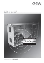
Possibilities without limitation<strong>GEA</strong> <strong>CAIRplus</strong>Air Handling Units | Operation Manual<strong>GEA</strong> Heat Exchangers / HVAC Systems
Table of Contents<strong>GEA</strong> <strong>CAIRplus</strong>Table of Contents1 Unit Type Code . . . . . . . . . . . . . . . . . . . . . . . . . . . . . . . . . . . . . 42 Safety and User Information . . . . . . . . . . . . . . . . . . . . . . . . . . 52.1 Availability of the operation manual . . . . . . . . . . . . . . . . . . . . . . . 52.2 Scope of the operation manual . . . . . . . . . . . . . . . . . . . . . . . . . . 52.3 Symbols used . . . . . . . . . . . . . . . . . . . . . . . . . . . . . . . . . . . . . . . 52.4 Labelling of the safety information . . . . . . . . . . . . . . . . . . . . . . . . 82.5 Safety-conscious working . . . . . . . . . . . . . . . . . . . . . . . . . . . . . . 92.6 Proper use . . . . . . . . . . . . . . . . . . . . . . . . . . . . . . . . . . . . . . . . . 102.7 Safety devices . . . . . . . . . . . . . . . . . . . . . . . . . . . . . . . . . . . . . . 102.8 Modifications and changes . . . . . . . . . . . . . . . . . . . . . . . . . . . . 112.9 Spare parts . . . . . . . . . . . . . . . . . . . . . . . . . . . . . . . . . . . . . . . . 112.10 Disposal . . . . . . . . . . . . . . . . . . . . . . . . . . . . . . . . . . . . . . . . . . . 112.11 Selection and qualifications of personnel . . . . . . . . . . . . . . . . . . 113 Technical Description . . . . . . . . . . . . . . . . . . . . . . . . . . . . . . . 123.1 Scope of performance . . . . . . . . . . . . . . . . . . . . . . . . . . . . . . . . 123.2 Unit design and operating principle . . . . . . . . . . . . . . . . . . . . . . 123.3 Technical data . . . . . . . . . . . . . . . . . . . . . . . . . . . . . . . . . . . . . . 143.4 Operating limits and range of application . . . . . . . . . . . . . . . . . . 144 Transport and Storage . . . . . . . . . . . . . . . . . . . . . . . . . . . . . . 184.1 Delivery . . . . . . . . . . . . . . . . . . . . . . . . . . . . . . . . . . . . . . . . . . . 184.2 Transportation . . . . . . . . . . . . . . . . . . . . . . . . . . . . . . . . . . . . . . 194.3 Storage . . . . . . . . . . . . . . . . . . . . . . . . . . . . . . . . . . . . . . . . . . . 225 Installation and Assembly . . . . . . . . . . . . . . . . . . . . . . . . . . . 235.1 Installation . . . . . . . . . . . . . . . . . . . . . . . . . . . . . . . . . . . . . . . . . 235.2 Assembling the unit . . . . . . . . . . . . . . . . . . . . . . . . . . . . . . . . . . 266 Installation of Components and Accessories . . . . . . . . . . . 386.1 Prerequisites . . . . . . . . . . . . . . . . . . . . . . . . . . . . . . . . . . . . . . . 386.2 Installation of air control and air conveying components . . . . . . 386.3 Installation of air handling components with coil connection . . . 396.4 Installation of accessories . . . . . . . . . . . . . . . . . . . . . . . . . . . . . 427 Electrical Connection . . . . . . . . . . . . . . . . . . . . . . . . . . . . . . . 437.1 Prerequisites . . . . . . . . . . . . . . . . . . . . . . . . . . . . . . . . . . . . . . . 437.2 Connecting the unit . . . . . . . . . . . . . . . . . . . . . . . . . . . . . . . . . . 448 Commissioning and Maintenance . . . . . . . . . . . . . . . . . . . . . 512 PR-2009-0096-GB • Subject to modifications • Status 07/2010
<strong>GEA</strong> <strong>CAIRplus</strong>Table of Contents8.1 Basic cleaning and maintenance tasks . . . . . . . . . . . . . . . . . . . 528.2 Maintenance interval checklist . . . . . . . . . . . . . . . . . . . . . . . . . 538.3 Units in general . . . . . . . . . . . . . . . . . . . . . . . . . . . . . . . . . . . . . 568.4 Fan unit and drives . . . . . . . . . . . . . . . . . . . . . . . . . . . . . . . . . . 588.5 Filter units . . . . . . . . . . . . . . . . . . . . . . . . . . . . . . . . . . . . . . . . . 628.6 Heater section . . . . . . . . . . . . . . . . . . . . . . . . . . . . . . . . . . . . . . 658.7 Cooler section . . . . . . . . . . . . . . . . . . . . . . . . . . . . . . . . . . . . . . 688.8 Evaporator/condenser . . . . . . . . . . . . . . . . . . . . . . . . . . . . . . . . 698.9 Heat pipe . . . . . . . . . . . . . . . . . . . . . . . . . . . . . . . . . . . . . . . . . . 708.10 Liquid-coupled heat exchanger . . . . . . . . . . . . . . . . . . . . . . . . . 718.11 Plate heat exchanger . . . . . . . . . . . . . . . . . . . . . . . . . . . . . . . . 718.12 Rotary heat exchanger . . . . . . . . . . . . . . . . . . . . . . . . . . . . . . . 738.13 Humidifier unit . . . . . . . . . . . . . . . . . . . . . . . . . . . . . . . . . . . . . . 738.14 Dampers and shut-off dampers . . . . . . . . . . . . . . . . . . . . . . . . . 748.15 Sound attenuator . . . . . . . . . . . . . . . . . . . . . . . . . . . . . . . . . . . . 749 Disassembly and Disposal . . . . . . . . . . . . . . . . . . . . . . . . . . . 759.1 Dismounting . . . . . . . . . . . . . . . . . . . . . . . . . . . . . . . . . . . . . . . 759.2 Disposal . . . . . . . . . . . . . . . . . . . . . . . . . . . . . . . . . . . . . . . . . . . 7510 Troubleshooting . . . . . . . . . . . . . . . . . . . . . . . . . . . . . . . . . . . 7611 Attachment . . . . . . . . . . . . . . . . . . . . . . . . . . . . . . . . . . . . . . . 7711.1 Maintenance Log Book <strong>CAIRplus</strong> . . . . . . . . . . . . . . . . . . . . . . . 77Copyright noteDisclosing, copying, distributing or taking any action in reliance on the contents of this document is strictlyprohibited without express prior consent. Violations entail liability for any damages or other liability arising.All rights in relation to patents, utility patents or design patents are reserved.PR-2009-0096-GB • Subject to modifications • Status 07/2010 3
Unit Type Code<strong>GEA</strong> <strong>CAIRplus</strong>1 Unit Type CodeA 1 2 8 0 6 4 V B V AUnit part 2 *Example: CAIR plus S 1 A # I H S E Z 1 2 8 0 6 4 V B V APrefix General Unit part 1Product family<strong>CAIRplus</strong> (air handling unit)Product groupSeriesUnit applicationclassThermalseparation CasingType of applicationInstallation locationDirection of airflowConfigurationCasing typeFunctionAir flowWidth of unitHeight of unitMaterial:internal skinMaterial:external skinMaterial:componentsMaterial: profilesS S unitX SX unit1 Standard without accessories2 Standard with accessories3 SpecialA AutomaticT CompleteK None# StandardR Standard, in accordance with guideline RLT 01H HygieneE Explosion-proofI Indoor installationA Outdoor installationD Ceiling mountingW Wall mountingU Underfloor installationH HorizontalV VerticalL L shapeS SingleN Side by sideÜ Double deckH Straight throughE Single casing(s)K Combined casingZ Supply airA Return airUnit width (internal dimension in cm)Unit height (internal dimension in cm)V Aluzinc AZ 185B Coated, RAL 90022 V2A stainless steel (material number 1.4301) or equal4 V4A stainless steel (material number 1.4571) or equalV Aluzinc AZ 185B Coated, RAL 9002S Coated, special colourV GalvanizedL CoatedK Coated, increased corrosion protectionA Aluminium, naturalG Coated, <strong>GEA</strong> greenB Coated, RAL 9002* Unit part 2 – additionally with side by side, double deck or straight through configuration4 PR-2009-0096-GB • Subject to modifications • Status 07/2010
<strong>GEA</strong> <strong>CAIRplus</strong>Safety and User Information2 Safety and User InformationThe <strong>GEA</strong> CAIR units are constructed in accordance with current technologicalstandards and recognised technical safety regulations.Use the units correctly and only when they are in perfect working order. Observethe operation manual and be aware of the dangers and safety precautions,otherwise there may be risk of death or injury to the user or third persons. Adverseaffects to the unit, connected units or other equipment may also occur.Have all faults repaired professionally without delay.Also observe the (safety) information provided by the manufacturers of individualcomponents.2.1 Availability of the operation manualThe accompanying operation manual includes important information about thesafe and correct operation of the unit.The operation manual is intended for use by fitting and installation companies,building services engineers, technical personnel or trained persons as well aselectrical and air-conditioning engineering specialists.This manual must always be available at the site where unit is in operation. Everyperson working with or around the unit must read and apply the informationcontained in the manual, paying particular attention to the safety instructions.2.2 Scope of the operation manualThis operation manual provides you with the necessary information about thefollowing subjects:– Transport and storage– Installation and assembly of the unit– Installation of components and accessories and electrical connection– Commissioning and maintenance– Disassembly and disposal2.3 Symbols usedThe following symbols are used to draw your attention to particular text sectionsin these operating instructions:– This symbol is used for normal lists.• This symbol indicates instructions to act. This symbol denotes the results of an action.NOTEThis symbol denotes additional information on use of the units.You will find the danger symbols in section „Labelling of the safety information“ onpage 8.PR-2009-0096-GB • Subject to modifications • Status 07/2010 5
Safety and User Information<strong>GEA</strong> <strong>CAIRplus</strong>2.3.1 Special warning/information signsThe following warning/information signs may be attached to the unit:When connecting, apply counter pressure with pipe wrench.Caution: risk of fire. Dirty (dust-laden) filters are inflammable.Switch off main switch before opening.Danger of injury. Only open when at a standstill.Data sheet and assembly instructions on the inside.These documents must be removed prior to commissioning.Do not start up the fan against closed dampers.Label for unit in areas where risk of explosion is present(as per 94/9/EC).Warning – explosion risk area.Potential equalisation.The unit must be connected to an external protective conductor at the points onthe base frame denoted by this symbol to achieve potential equalisation.6 PR-2009-0096-GB • Subject to modifications • Status 07/2010
<strong>GEA</strong> <strong>CAIRplus</strong>Safety and User Information2.3.2 Function signsGeneral symbol for fan orcompressor showing airflowdirectionAir heater/cooler for heatrecovery systemAir/water ECOFLOWSound attenuator in unitAir heater/cooler for heatrecovery systemAir/refrigerant ECOSTATGeneral symbol for air filtershowing airflow directionAir heater/cooler for heatrecovery systemAir/air ECOPLATSymbol for HEPA filtershowing airflow directionAir heater/cooler for heatrecovery systemAir/air ECOROTDamper opposed operationGeneral symbol for air humidifierAir heater, air/waterGeneral symbol for controllerAir cooler, air/waterDroplet eliminatorAir cooler,air/steam/refrigernatPR-2009-0096-GB • Subject to modifications • Status 07/2010 7
Safety and User Information<strong>GEA</strong> <strong>CAIRplus</strong>2.4 Labelling of the safety informationThe following designations and symbols have been used in this manual to denotesafety information:ELECTRICAL HAZARD!This symbol indicates that there is a risk of electrical shock when carrying outthe relevant task(s).PERSONAL INJURY!Here you will find special information as well as requirements and restrictionsfor preventing personal injury.DANGER FROM ROTATING UNIT PARTS!Here you will find special information as well as rules and restrictions for theprevention of personal injury due to rotating parts of the unit.DANGER DUE TO OVERHEAD LOADS!Here you can find special information as well as rules and restrictions for theprevention of personal injury and damage to units due to falling parts.DANGER DUE TO HOT SURFACES!Here you can find special information as well as rules and restrictions for theprevention of personal injury due to hot surfaces.DANGER OF SCALDING!Here you can find special information as well as rules and restrictions for theprevention of personal injury due to scalding, e.g. by steam.DANGER DUE TO EXPLOSION RISK AREA!Here you can find special information as well as rules and restrictions for theprevention of personal injury and damage to units in explosion risk areas.DANGER DUE TO COMBUSTIBLE SUBSTANCES!Here you will find special information as well as requirements and regulationsfor the prevention of personal injury due to fire.DANGER FROM SHARP EDGES!Here you can find special information as well as rules and restrictions for theprevention of personal injury due to cutting by thin sheet metal.ENVIRONMENTAL DAMAGE!Here you will find special information, rules and restrictions for the preventionof damage to the environment including information on any national environmentalprotection regulations in force.DAMAGE TO THE UNIT!Here you will find special information, rules and restrictions regarding theprevention of damage to the unit.8 PR-2009-0096-GB • Subject to modifications • Status 07/2010
<strong>GEA</strong> <strong>CAIRplus</strong>Safety and User Information2.5 Safety-conscious workingObserve the following when carrying out installation, maintenance and repair work:When working on or around the mains power supplyELECTRICAL HAZARD!All power supply connections must be switched off and checked to see if theyare voltage-free and then secured against unintentional switching on.Earth and short-circuit them and cover over any neighbouring electricallyconducting parts or block them off. Failure to do so may lead to serious injuryor death.Working in explosion risk areasDANGER DUE TO EXPLOSION RISK AREA!The unit may only be operated under the conditions described on the type plate.An explosion risk area may be present inside and/or outside the unit when it isin operation and also when it has been shut down – it must therefore beassumed that an explosion risk area is present, even when the unit has beenshut down.When carrying out work in general:PERSONAL INJURY!A danger of injury exists when the units are in operation:– Danger of impacts – doors on the discharge side may be flung open– Danger of crushing due to underpressure at doors on suction side– Danger due to rotating parts such as fans etc.DAMAGE TO THE UNIT!If dampers are closed when the system is in operation, the units may bedamaged beyond repair by under- or overpressure, particularly if the dampersare closed abruptly.DANGER FROM SHARP EDGES!When working on the unit in general there is a danger of cuts being inflicted bythin sheet metal and fins. This applies in particular when carrying outmaintenance and cleaning work on the surfaces of heater and cooler coil fins.Work may only be carried out on the unit if– all poles of the power supply have been disconnected,– the unit is secured to prevent it being switched back on(also refer to “Electrical hazard”),– all moving parts – particularly the fan impeller, motor, rotary heat exchanger,control and shut-off dampers – have come to a standstill: wait at least5 minutes after switching off the unit,– the heat exchangers have cooled down to ambient temperature.Once work on the unit has been carried out, it must be ensured that– all protective devices are functioning effectively – for example, the protectiveenclosure for the fan (door protection grille, safety guard) must be locked– no persons are present in danger areas.PR-2009-0096-GB • Subject to modifications • Status 07/2010 9
Safety and User Information<strong>GEA</strong> <strong>CAIRplus</strong>2.6 Proper useThe <strong>GEA</strong> CAIR units are intended exclusively for handling of air for the followingpurposes:– filtering of air with normal levels of contamination,– filtering of air in cleanroom environments (special cleanroom model),– heating and/or cooling of air,– humidifying and/or dehumidifying of air,– heat removal and/or heat recovery,– filtering and treatment of air with a high moisture content and/or with highlevels of contamination (special models, for example for swimming pool orkitchen exhaust applications),– combinations of the above tasks.Proper use also includes observance of the operation manual as well as theinspection and maintenance intervals specified by <strong>GEA</strong>.Improper useAny use other than that described above is considered improper. If necessary,check whether your <strong>GEA</strong> CAIR units are suitable for your intended purposes. Themanufacturer/supplier is not liable for any damages arising from improper use.The user alone bears the risk.The <strong>GEA</strong> CAIR is not suitable for the handling of abrasive media.PERSONAL INJURY!The <strong>GEA</strong> CAIR units may not be operated in the following environments:– in explosion risk areas, unless authorisation has been granted for use of therelevant application in these areas (air handling and low profile units wherespecial precautions have been taken to prevent explosions in accordancewith ATEX Guideline 94/9/EC);– in rooms where conductive dusts are present;– in rooms where strong electromagnetic fields are present;– in rooms with aggressive environments that may attack plastics or causecorrosion (especially in environments where zinc is particularly susceptibleto corrosion).2.7 Safety devicesThe following are installed depending on the equipment supplied with the unit:– Cabinet locks/lockable handles on panels with sash fasteners and doors– Door protection grilles on fan sections– V-belt drives with belt guards.10 PR-2009-0096-GB • Subject to modifications • Status 07/2010
<strong>GEA</strong> <strong>CAIRplus</strong>Safety and User Information2.8 Modifications and changesYou must not modify, add to, or convert, the unit in any way. Any conversions ormodifications to the unit will invalidate the CE conformity.If the delivered units are disassembled by others on-site, the factory warranty isinvalidated. In this case professional supervision by <strong>GEA</strong> Happel Service GmbHshould be organized in advance.2.9 Spare partsYou may use only genuine <strong>GEA</strong> spare parts as <strong>GEA</strong> will not be held liable forclaims arising from the use of third party spare parts.2.10 DisposalOperating and auxiliary materials, components and filters must be disposed of ina safe and environmentally friendly manner.2.11 Selection and qualifications of personnelEvery person authorised to work on or around the unit must have read this entireoperation manual and understood it completely – particularly the chapter onsafety. It is too late to do this during work.All work must only be carried out by specialists with sufficient knowledge basedon professional training and experience in the following:– Regulations concerning health and safety in the workplace– Accident prevention regulations– Directives and recognised codes of practiceAll skilled persons must be able to assess what the work entrusted to them entailsand must be able to recognise and avoid any inherent dangers.PR-2009-0096-GB • Subject to modifications • Status 07/2010 11
Technical Description<strong>GEA</strong> <strong>CAIRplus</strong>3 Technical Description3.1 Scope of performanceOne of the main purposes of <strong>GEA</strong> CAIR units is to facilitate energy-efficient in/outventilation of rooms. Due to their modular construction, the units may be configuredseparately to cater for special air-handling requirements. The air conveyedmay be filtered, heated, cooled, humidified or dehumidified, depending on theparticular application. The aim is to ensure that the quantity and condition of thetreated air meets the customer's requirements.<strong>GEA</strong> CAIR units are generally used in the leisure and commercial/industrialsectors for the transportation and treatment of “normal” air. These units may alsobe specially adapted for cleanroom and hygiene applications. <strong>GEA</strong> CAIR unitsthat include special explosion protection precautions and comply with ATEXGuideline 94/9/EC are clearly identified as such. These units are supplied with anadditional operation manual that must be read and applied in practice.To save energy, a range of components are available such as rotary heatexchangers, plate heat exchangers, heat pipes and liquid-coupled heatexchangers for the recovery of heat, and also the partial recovery of moisture.Units of different sizes and capacities are available. Depending on the application,<strong>GEA</strong> CAIR units can provide a vertical or horizontal airflow with double deck,side by side and straight through arrangements. Units are available for installationindoors or outdoors.The modular design of the <strong>GEA</strong> CAIR units makes it possible to split up units intosuitable delivery packages that will pass through the available on-site openingsduring installation. <strong>GEA</strong> CAIR units are also suitable for the modernisation ofexisting buildings due to the range of unit sizes available and the option of orderingthe units in small delivery packages.3.2 Unit design and operating principleA variety of configurations is possible due to the modular design of the units andthe various applications.The basic design of the unit and its operating principle is illustrated below usingexamples.F.A. = fresh airS.A. = supply airR.A. = return airE.A. = extract air12 PR-2009-0096-GB • Subject to modifications • Status 07/2010
<strong>GEA</strong> <strong>CAIRplus</strong>Technical DescriptionFig. 3-1 shows a <strong>GEA</strong> CAIR unit that is used exclusively for conveying air. Theunit consists of a casing incorporating a base frame, fan unit, damper on the freshair side, two flexible connectors and a service switch.Service switchS.A.F.A.Fig. 3-1:Unit for handling airSupply and exhaust air units can be combined and used to add return air to supplyair (completely, partially and/or intermittently). This is mainly employed to saveheating or cooling energy.Fig. 3-2 depicts a combined exhaust air unit and supply air unit with additionalfilter and heater section. The units are connected via mixing boxes.S.A.Service switchF.A.E.A.R.A.Fig. 3-2:Combined supply and exhaust air unit with mixing boxIn contrast to the straight through arrangement shown in Fig. 3-2,Fig. 3-3 shows a double deck combined supply and exhaust air unit with heatrecovery facility. In addition to the conveying, filtering, heating and mixing of air,this unit is also capable of recovering energy via a plate heat exchanger.R.A.F.A.S.A.E.A.Fig. 3-3:Combined supply and exhaust air unit with heat recoveryPR-2009-0096-GB • Subject to modifications • Status 07/2010 13
Technical Description<strong>GEA</strong> <strong>CAIRplus</strong>3.3 Technical dataRefer to the order documentation for the specific configuration of your orderspecific<strong>GEA</strong> CAIR unit (unit drawing with dimensions and technical data).3.4 Operating limits and range of applicationNOTESPlease carefully observe the unit type plate and the operation manuals for theaccessories supplied.Please refer to the accompanying documentation for the range of application ofspecial built-in parts.Always use frost protection and antifreeze for heating and cooling media if thereis a risk of frost.The range of application for <strong>GEA</strong> CAIR special units are available on request.3.4.1 Environmental conditionsFresh airfrom -25°C to +60°CReturn air from 0 °C to +80 °CAir humidityMax. operating pressureand temperatureMin. operating temperatureNOTE ON EXTREME CONDITIONSIn addition to the air temperature/air humidity of the flow medium, the temperature/humidityof the surrounding air are also key factors. Observe the condensationlimits.max. 18 g/kg of dry air, depending on the temperatureHeater/cooler coil 16 bar / 90 °CHeater/cooler coil 6 °CNote about extremeconditionsApart from air temperature and air humidity of the medium, the ambient airtemperature and air humidity are important. Environmental impact like proximityto sea or ocean must be taken into account when selecting material quality.14 PR-2009-0096-GB • Subject to modifications • Status 07/2010
<strong>GEA</strong> <strong>CAIRplus</strong>Technical Description3.4.2 Permitted storage conditions / permitted air conditions for non-installed units.Air temperatureAir humidity-10°C to +50°<strong>CS</strong>tore units in a dry, non-condensing environment3.4.3 Supply voltageThe required voltage is stated in the order-specific documentation,e.g. AC 230 V/50 Hz (1-phase) or AC 400 V/50 Hz (3-phase).3.4.4 Condensation limitsPlease pay due attention to condensation limits!The following diagrams illustrate condensation limits in retation to temperatureand relative humidity at the installation site - for the unit series CAIR plus S, <strong>CAIRplus</strong> SX T and CAIR plus SX K.Example ofmeasured values:The diagrams are based on normal air values and were calculated with a help ofa model box. The given values are approximate figures and can not be used as aguaratneee for avoiding condensation. Deviation may occur when consideringdifferent unit components.Air temperature unit inner side in °CAir temperature unit outer side in °CPR-2009-0096-GB • Subject to modifications • Status 07/2010 15
Technical Description<strong>GEA</strong> <strong>CAIRplus</strong>CAIR plus S Condensation diagram for kb-value: 0,46Air temperature unit outer side in °CCAIR plus SX T= thermally separatedCondensation diagram for kb-value: 0,7Air temperature unit inner side in °CAir temperature unit inner side in °CAir temperature unit outer side in °C16 PR-2009-0096-GB • Subject to modifications • Status 07/2010
<strong>GEA</strong> <strong>CAIRplus</strong>Technical DescriptionCAIR plus SX K= no thermal separationCondensation diagram for kb-value: 0,5Air temperature unit outer side in °CCAIR plus SX M= partialthermal separationCondensation diagram for kb-value: 0,62Air temperature unit inner side in °CAir temperature unit inner side in °CAir temperature unit outer side in °CPR-2009-0096-GB • Subject to modifications • Status 07/2010 17
Transport and Storage<strong>GEA</strong> <strong>CAIRplus</strong>4 Transport and Storage4.1 DeliveryThe unit can be delivered as an integral whole or in separate delivery units ontransport pallets.• When the unit is delivered, check that the delivery is correct according to thedelivery note, and also check for completeness.NOTEObserve the information regarding transit damage on the packaging or in thedelivery notes.What steps should you takein the event of transitdamage?Packaging damaged externally1 Unpack the equipment in the presence of the lorry driver and have thedamage acknowledged in the shipping order.2 Inform the <strong>GEA</strong> sales subsidiary immediately.No signs of external damage to packaging, contents damaged1 Once you have established the extent of the damage, notify the <strong>GEA</strong> salessubsidiary in writing.2 Document the situation photographically.3 Any transit damage must be reported no later than 4 days following delivery.Processing of claims will not be possible unless the above steps have been taken.In both cases consult the <strong>GEA</strong> sales subsidiary before installing the units.18 PR-2009-0096-GB • Subject to modifications • Status 07/2010
<strong>GEA</strong> <strong>CAIRplus</strong>Transport and Storage4.2 TransportationNOTEOnly transport the unit in its original packaging.Only remove the original packaging just before the installation starts.• Only transport the unit using the transport lugs/devices provided by themanufacturer.• Wear safety footwear and gloves when transporting the unit to ensure yoursafety.DANGER DUE TO OVERHEAD LOADS!Never enter the area beneath freely suspended loads as there is always thedanger that hoisting devices, lifting accessories or ropes/chains may bedamaged, which may lead to serious injury or death.• Before transporting the unit, make sure that all doors, panels with sashfasteners and panels are closed and secured.• Only use hoisting devices with sufficient load-carrying capacity.• Never use damaged hoisting devices.• Ropes/chains should not be knotted or come into contact with sharp edges.• Only use ropes/chains of the same length.• Move the unit carefully without sudden or jerky movements.• Do not set the unit down abruptly or bump it.PR-2009-0096-GB • Subject to modifications • Status 07/2010 19
Transport and Storage<strong>GEA</strong> <strong>CAIRplus</strong>4.2.1 Lifting the unit – transport lugs on roof (provided with individual units weighing up to 1500 kg)PERSONAL INJURY!Only use the transport lugs provided by <strong>GEA</strong>! Make sure that these are firmlyseated before lifting the equipment. • Only vertical loading of transport lugs is allowed.• Lugs may not be used to suspend the unit on apermanent basis.• Transport lugs may not be loaded laterally(lateral pulling of unit)• Suspension angle may not exceed 60°.• Transport lugs may only be used once.• No other loads may be lifted together with the individualunit.• When installing outdoor units, particular care should betaken to ensure that the roof sheeting is not damagedby the hoisting devices.Fig. 4-1:Transport lugs for individual unitsweighing up to 1500 kg20 PR-2009-0096-GB • Subject to modifications • Status 07/2010
<strong>GEA</strong> <strong>CAIRplus</strong>Transport and Storage4.2.2 Lifting the unit – transport device on base frame (provided with delivery units weighing up to 4000 kg)PERSONAL INJURY!Only use the transport devices provided by <strong>GEA</strong>! Make sure that these arefirmly seated before lifting the equipment.Fig. 4-2:Transport lugs for individual unitsweighing up to 4000 kg• The units may only be lifted using the transport devicesattached to the base frame.• Use the hoisting device (not included in scope of <strong>GEA</strong>delivery) as shown.• Use supplied timber spacers to provide protection atthe edges• When using shackles - ropes/slings do not have to bepushed through the opening• The suspension angle must not exceed 60°.• To make sure that the load does not slip or tilt, payattention to its centre of gravity when lifting it.• Transport devices may be used only once.• They may not be used to suspend the unit on apermanent basis.• No other loads should be lifted together with thedelivery unit.• When installing units outdoors, particular care shouldbe taken to ensure that the roof sheeting is notdamaged by the hoisting devices.4.2.3 Transportation with pallet truck or forklift truck• Always use the unit base frame or the pallet supplied as the supporting surfaceduring transportation.• Units must not be lifted without the base frame unless the unit profiles aresufficiently protected.• When transporting the unit using a forklift, both base frame profiles must beresting on the forks.• The centre of gravity and load distribution must be taken into account.DAMAGE TO THE UNIT!Never stack units on top of one another for transportation.Always transport units individually.The stacking of units and other components that are not part of the unit is notpermitted.This is only permissible if the necessary load-bearing capacity has beenspecially incorporated into the units delivered from the <strong>GEA</strong> works.PR-2009-0096-GB • Subject to modifications • Status 07/2010 21
Transport and Storage<strong>GEA</strong> <strong>CAIRplus</strong>4.3 StorageNOTEObserve the permissible storage conditions when storing the unit. Only removethe original packaging just before the installation starts.Protect the unit before commissioning against building dust and dirt as well asdamage.Suitable measures must be taken to protect units delivered without packagingagainst building dust and dirt prior to commissioning. Care must be taken toensure that condensation cannot form below packaging supplied by others (byensuring the correct distance between the packaging and the casing).• Always place units on an even surface during storage or intermediate storage.• Protect units from bumps and knocks which may damage the casing andprojecting components.• If commissioning is not carried out within three months of the delivery the beltdrive must be slackened.• Turn the motor axle and fan through at least 2 revolutions every 3 months.Permitted storage conditions / air conditions for non-installed units.Air temperatureAir humidity-10°C to +50°<strong>CS</strong>tore units in a dry, non-condensing environment22 PR-2009-0096-GB • Subject to modifications • Status 07/2010
<strong>GEA</strong> <strong>CAIRplus</strong>Installation and Assembly5 Installation and AssemblyHere you will find information regarding the assembly and installation of theunit.This may only be carried out by specialistswith the necessary knowledge of relevant accident prevention regulations andother standard regulations relevant to health and safety in the workplace, basedon their training and experience.The unit should be installed in such a way that it is accessible only to technicalpersonnel with the appropriate authorisation and training.The unit may only be assembled in accordance with the application shown inthe technical information supplied with the unit.The units must not be stacked with other components that are not part of theunit.This is only permissible if the necessary load-bearing capacity has beenspecially incorporated into the units delivered from the <strong>GEA</strong> works.When connecting the duct it must be ensured that no foreign matter can enter theunit. If necessary, a suitable wire mesh guard can be installed by others at theopening on the discharge/intake side of the unit.DAMAGE TO THE UNIT!When mounting <strong>GEA</strong> CAIR units care must be taken to ensure that no loadsare applied to the floor panels. During assembly work suitable measures shouldbe taken to ensure that any loads are spread across the bottom profiles (e.g.using grid walkways).5.1 Installation5.1.1 Installation locationThe unit must be installed at a location that fulfils the following requirements:– The substructure must be level and stable.– The maximum deflection of the substructure may not exceed 4 mm per metre.– In units where a condensate drain is installed, the height of the substructuremust be at least the same as to the required siphon height (see siphon).– Make sure that no damage to the installation location or the environment canbe caused by escaping media.Fig. 5-1:Installation locationPR-2009-0096-GB • Subject to modifications • Status 07/2010 23
Installation and Assembly<strong>GEA</strong> <strong>CAIRplus</strong>When installing a spray humidifier, the remainingmodules must be balanced by installing a plinth or unitfeet that correspond to the height of the trough.Fig. 5-2:Height compensation with sprayhumidifier5.1.2 Minimum clearances• In order to be able to remove fans, heat exchangers,droplet eliminators, etc. and also perform servicing andmaintenance, a minimum clearance of one unit widthmust be maintained on the operating side.• A minimum clearance of 600 mm between the rear ofthe unit and the wall must be maintained if the internaldividing joint connectors cannot be used due to the unitconfiguration.Fig. 5-3:Minimum clearance5.1.3 Foundation construction for indoor installation• The subconstruction may project a maximum of 20 mmbeyond the outer edge of the unit to facilitate theinstallation of cover panels or accessories, such assiphons.• The bearing points for the subconstruction must belocated at every unit’s dividing joint and the maximumdistance between bearing points in the longitudinaldirection must not exceed 1600 mm.• Units arranged side by side must be supportedcentrally (see illustration).Fig. 5-4: Foundation –side by side arrangement24 PR-2009-0096-GB • Subject to modifications • Status 07/2010
<strong>GEA</strong> <strong>CAIRplus</strong>Installation and Assembly5.1.4 Foundation construction for outdoor installation (weatherproof, roof frame)NOTE!<strong>GEA</strong> units for outside installation are not a substitution for roof!In compliance with prEN 13053 and VDI 3803 it is not allowed to use surfacesof weatherproof units to support parts of a building or in a similar way substitutea roof.• Instructions for „Foundation construction for indoor installation“ on page 23should be applied.• Choose an installation location where the fresh air intake will not be facing themain wind direction.• In areas where there is a heavy amount of snowfall, the unit must be installedin a location where its operation will not be affected by snow. A suitable heightfor the subconstruction must be selected.• If the unit is to be mounted on a roof, then the load-bearing capability of theroof and its supporting structure must be checked. Consult a structuralengineer if necessary.• The roof edge below the unit, as well as ducts and other roof openings mustbe performed waterproof by others.• The roof frame must be insulated to prevent condensation. For information oninstallation, see „Preparing installation of roof“ on page 30.Fig. 5-5:Foundation constructionon concrete baseFig. 5-6:Foundation construction onsteam beam by othersFig. 5-7:Foundation construction on steel supports by othersPR-2009-0096-GB • Subject to modifications • Status 07/2010 25
Installation and Assembly<strong>GEA</strong> <strong>CAIRplus</strong>NOTEParticular care must be taken to ensure compliance with the precisedimensions of roof openings and to ensure that the foundation is level.5.1.5 Structure-borne sound attenuationIn order to reduce the transfer of vibrations from the unit to the supportingstructure, anti-vibration mounts and structure-borne sound attenuatingmats must be installed.– We recommend that the foundation is isolated from the unit using rubberplates, for example, where the unit is installed on level ground and no specialstructure-borne sound isolation requirements exist.– We recommend the use of commercially available spring elements for ceilingmounting.– For very special acoustic requirements please consult an acoustics engineerto select the most suitable structure-borne sound attenuation method.5.2 Assembling the unitNOTEFor detailed information, please refer only to the documentation enclosed withthe unit. Data sheet, installation instructions, small parts and accessoriessupplied loose can be found in the unit part specified in the parts list.DAMAGE TO THE UNIT!Fittings/attachments etc. not provided by the manufacturer that could cause aleak must not be mounted on the walls or frame of the unit. The unit’s operabilitymust be maintained.Tools required: – Electric screwdriver, drill– Holder for bits/sockets– Sockets, sizes 8, 10– Slotted head screw bits, sizes 2, 3– Open-ended spanners sizes 8, 13, 17– Screw drivers 4.5-6.5– Hexagon socket size 6– Tensioning belts or suitable hoisting device26 PR-2009-0096-GB • Subject to modifications • Status 07/2010
<strong>GEA</strong> <strong>CAIRplus</strong>Installation and Assembly5.2.1 Removing transportation lugs/device/locks• All transportation lugs/devices/locks marked yellow on and in the unit must beremoved prior to assembly.• Remove the transportation locks on the fan.Transport lug for roof• The transportation lugs on the roof must be removed.• Remove the screws on the end panels and secure thesupplied M8 x 70 screw.• Remove the lug, screw and bushing at the dividingjoint, then secure the supplied M8 x 30 screw.Support bushingCylinder screwPlastic washerNOTE!Because of danger of collision with transportlugs - externally mounted dampers/louvres,flexible connections are partially suppliedloose. These components are field-mountedand sealed by others.Fig. 5-8:Transport lugs – roof, end wall anddividing joint• Remove the transportation device on the base frame.Fig. 5-9:Transport device on base frameNOTETransportation lugs/device must not be used to suspend the units on apermanent basis.Transportation lugs/device may be used only once.PR-2009-0096-GB • Subject to modifications • Status 07/2010 27
Installation and Assembly<strong>GEA</strong> <strong>CAIRplus</strong>5.2.2 Installation of individual modulesTo assemble individual modules (dividing joint) proceed as follows:• Affix provided sealings to the dividing joint(speacial assembly instructions provided with thesealings).Fig. 5-10: Installing individual modulesDAMAGE TO THE UNIT!Do not attach tensioning belts/hoisting devices to heat exchanger connections,condensate drains and door handles or use these to pull or push theequipment!• Position the unit parts as close to one another as possible prior to assembly.Only use the unit base frame to pull the individual components together. Unitsthat do not have a base frame must be pulled together with tensioning belts.These must be positioned round the profiles in the base or roof area.max. 100 mmFig. 5-11: Unit with base frameFig. 5-12: Unit without base frame28 PR-2009-0096-GB • Subject to modifications • Status 07/2010
<strong>GEA</strong> <strong>CAIRplus</strong>Installation and Assembly• First of all, screw the exterior dividing joint connectors together.• Mount caps.Fig. 5-13: External view• If the rear of the unit is not accessible, screw the interior dividing jointconnectors in the corner together.Fig. 5-14: Internal viewNOTEAn additional dividing joint connector is provided in the middle of the profile(internally) where the internal unit width or height is 1280 mm or more – thismust also be screwed tight.• Seal pipe and cable ducts to prevent air leakage and condensation using PURfoam, for example (not included in <strong>GEA</strong> delivery scope).Fig. 5-15: Pipe ductAdditional measure for double-deck/side by side units• Connect both unit parts using the provided plates.Fig. 5-16: Connectingunit partsPR-2009-0096-GB • Subject to modifications • Status 07/2010 29
Installation and Assembly<strong>GEA</strong> <strong>CAIRplus</strong>Additional measure for hygiene units• Clean and seal all internal dividing joint grooves in the floor area.The sealant is included in the scope of delivery for hygiene units.Fig. 5-17: Dividing joints5.2.3 Preparing installation of roof• Remove all transport lugs (1).111 2• Use sealing washers to tighten all screws (2).Fig. 5-18: Preparing installation of roof30 PR-2009-0096-GB • Subject to modifications • Status 07/2010
<strong>GEA</strong> <strong>CAIRplus</strong>Installation and Assembly5.2.4 Installing flat roof (<strong>CAIRplus</strong> S)Installing panel for dividing joint• Secure the loosely enclosed panel for dividing joints.Fig. 5-19: Installing panel for dividing joints• Cover all dividing joints with clamping profiles.• Remove the last steel clasp and seal this point withglue (1).1Fig. 5-20: Covering and glueing dividing jointsInstalling cross panels• Apply the glue evenly on the surface.• Screw the cross panels using four provided positionsand make a concave groove in the glue.Fig. 5-21: Installing cross panelsPR-2009-0096-GB • Subject to modifications • Status 07/2010 31
Installation and Assembly<strong>GEA</strong> <strong>CAIRplus</strong>5.2.5 Installing inclinded/bossed roof (<strong>CAIRplus</strong> SX)• Secure the loosely enclosed panel for dividing joints.Fig. 5-22: Installing panel for dividing jointsSingle units 064.xxx to 160.xxx and side-by-side 064.xxx to 096.xxx1• Seal the roof panel joints (1) using supplied glue.• Attach the loosely enclosed sliding strips (2).• Manually bend the projecting lobe (3) 90° downwards.32Fig. 5-23: Single units 064.xxx to 160.xxxand side-by-side units 064.xxx to 096.xxx32 PR-2009-0096-GB • Subject to modifications • Status 07/2010
<strong>GEA</strong> <strong>CAIRplus</strong>Installation and AssemblySingle unit 188.xxx to 252.xxx with inclined roof variant1• Secure the loosely enclosed panel for dividing joints, asdecribed above.• Attach the enclosed sliding strips (1) from both sides.• Use a screwdriver to ensure that a lug is run below theopposite sliding strip.1• Use a glue to seal the sliding strips (2).2• Secure the mounting screws (3).3Fig. 5-24: Single units 188.xxx to 252.xxxwith inclided roofPR-2009-0096-GB • Subject to modifications • Status 07/2010 33
Installation and Assembly<strong>GEA</strong> <strong>CAIRplus</strong>Single units 280.xxx and 312.xxx and side-by-side 128.xxx to 160.xxx• Secure the loosely enclosed panel for dividing joints, asdescribed on page 32.• Seal the roof panel joints (1) using enclosed glue .• Attach the enclosed sliding strips (2) from both sides.• Secure the mounting screws (3).132Fig. 5-25: Single units 280.xxx and 312.xxxand side-by-side 128.xxx to 160.xxx34 PR-2009-0096-GB • Subject to modifications • Status 07/2010
<strong>GEA</strong> <strong>CAIRplus</strong>Installation and AssemblyRoof panels with intermediate divisions1• For roof panels with intermediate divisions - attach theloosely enclosed roof sliding panel (1).• On each front wall secure a terminating panel (2).• Apply some glue (3), as presented in the drawing.• Clip on the loosely enclosed weather-proof slidingintermediate parts (4) and use the supplied screws tosecure them.243Fig. 5-26: Roof panels with intermediate divisionsDetails on side-by-side units with an offset, sizes 128.xxx and 160.xxx• Depending on the division of delivery units, the enclosedroof panel „side-by-side casing“ (1) must bemounted, as presented in the drawing.1Fig. 5-27: Side-by-side models with offsetunits sizes 128.xxx and 160.xxxPR-2009-0096-GB • Subject to modifications • Status 07/2010 35
Installation and Assembly<strong>GEA</strong> <strong>CAIRplus</strong>5.2.6 Roof installation for double deck unit• Roof installation with double deck units is identitical tothe installation of single units – refer to the descriptionon page 30.1• Apply the glue evenly on the surface.• Screw the intermediate panel with front wall (1).• Aftet that make a concave groove in the glue.Fig. 5-28: Roof installation for double deck unit36 PR-2009-0096-GB • Subject to modifications • Status 07/2010
<strong>GEA</strong> <strong>CAIRplus</strong>Installation and Assembly5.2.7 Roof installation for Ecorot side-by-side unit• Roof installation for Ecorot side-by-side units isidentitical to the installation of single units – refer to thedescription on page 30.1• Apply the glue evenly on the surface.• Screw the intermediate panel with front wall (1).• Aftet that make a concave groove in the glue.Fig. 5-29: Roof installtion for Ecorot side-by-sideunitsPR-2009-0096-GB • Subject to modifications • Status 07/2010 37
Installation of Components and Accessories<strong>GEA</strong> <strong>CAIRplus</strong>6 Installation of Components and AccessoriesIn line with the connection of heat exchangers, humidifiers etc., the coilconnection may only be carried out by specialists with the necessaryknowledge of relevant accident prevention regulations and other standardregulations relevant to health and safety in the workplace, based on theirtraining and experience.DAMAGE TO THE UNIT!When mounting <strong>GEA</strong> CAIR units care must be taken to ensure that no loadsare applied to the floor panels. During installation work suitable measuresshould be taken to ensure that any loads are spread across the bottom profiles(e.g. using grid walkways).6.1 Prerequisites• Check the unit for external damage and check whether it has been properlyassembled and anchored.• Check whether anti-vibration and structure-borne sound attenuating matshave been provided. This means that either:– the foundation has been isolated from the unit using rubber plates (forexample) where the unit is installed on level ground and no specialstructure-borne sound isolation requirements exist;– or, in the case of ceiling mounting, commercially available spring elementshave been used;– or, where very special acoustic requirements exist, an acoustics engineerhas been consulted when selecting the most suitable structure-bornesound attenuation method.• Before you start with the coil connection, check the following:– Drain valves must be installed at all low points in the water system toensure that the water circuit can be fully drained in order to carry outmaintenance or repairs.– A water drain with shut-off valve must be installed in order to drain the unit’swater system.– Air vents must be installed at all the high points of the water system ateasily accessible locations.• Ensure that the piping system is flushed through until it is clean by others anda cleaning record compiled.6.2 Installation of air control and air conveying componentsIn order to prevent the transmission of structure-borne sound, a tension-freeconnection between air ducts and the unit must be made using elastic connectorsor structure-borne sound attenuators (also compare „Structure-borne soundattenuation“ on page 26).If you are connecting air ducts to the units via flexible connectors, the installationlength of the connectors must be less than their extended length.38 PR-2009-0096-GB • Subject to modifications • Status 07/2010
<strong>GEA</strong> <strong>CAIRplus</strong>Installation of Components and Accessories6.3 Installation of air handling components with coil connectionRecommendations on water quality for heat exchangers that operate usinglow pressure hot water (LPHW) and chilled water:A good water quality – e.g. salt and lime-free drinking water – increases thelifetime and efficiency of the heat exchanger.• Check the limiting values shown in the table annually to prevent damage tothe hydraulic system and its components.If necessary inhibitors must be added.NoteThese limiting values areonly basic informationabout the water qualityand do not form anybasis for a guarantee!Description Symbol ValuesHydrogen ion concentration pH 7.5 − 9 < 7> 9Calcium and magnesiumcontentHardness(Ca/Mg)Effects in event ofdeviationCorrosionFouling4 − 8.5 °D > 8.5 FoulingChloride ions Cl – < 50 ppm CorrosionIron ions Fe³ + < 0.5 ppm CorrosionMagnesium ions Mg² + < 0.05 ppm CorrosionCarbon dioxide CO 2 < 10 ppm CorrosionHydrogen sulphate H 2 S < 50 ppb CorrosionOxygen O 2 < 0.1 ppm CorrosionChlorine Cl 2 < 0.5 ppm CorrosionAmmonia NH 3 < 0.5 ppm CorrosionRatio of carbons/sulphates HCO 3 ² - /SO 4 ² - > 1 < 1 Corrosion1/1.78 °D = 1 °Fr with 1 °Fr = 10 g CaCO 3 /m³ppm = parts per million (mg/l)ppb = parts per billion (μg/l)6.3.1 Installation of air handling components for cooling/heatingDAMAGE TO THE UNIT!When connecting the heat exchanger, counter force must be applied usingpliers to prevent damage.The connections to the heat exchanger by others must always be tension-free.Mechanical and static loads must not be applied to the connecting piece.The heat exchanger must be connected in accordance with the counter flowprinciple (air and water heat exchanger flow in opposite directions).• Protect the surfaces of the fins in the heat exchanger from damage.• Connect pipe system by others to the water inlet and outlet. The inlet andoutlet coil connections are marked using adhesive labels.• Insulate pipes by others.PR-2009-0096-GB • Subject to modifications • Status 07/2010 39
Installation of Components and Accessories<strong>GEA</strong> <strong>CAIRplus</strong>In addition, for air handling components that perform cooling function:• Insulate coil connections and pipes once the installation has been carried outto prevent the formation of condensation water. Condensate water that is formed accumulates in the stainless steelcondensate tray and is drained via a drain spigot mounted on the condensatetray.• Install a siphon (see „Connecting siphon and water drains“ on page 41).In addition, for units with fresh-air or mixed-air operation:DAMAGE TO THE UNIT!The heat exchanger in the unit must be protected from the formation of ice andfreezing at ambient temperatures below the freezing point.Use antifreeze in the water circuit if necessary.NOTEGlycol may be used providing that it does not exceed 50 % of the overallvolume.A higher quantity can cause operational faults.6.3.2 Installation of evaporator/condenser componentsENVIRONMENTAL DAMAGE!Dispose of any liquid spills (refrigerant) in an environmentally sustainablemanner in accordance with the locally applicable laws and regulations.• Open and use the service connections using only special tools and fittings. The units are filled with protective gas that audibly discharges when theconnection caps are removed.6.3.3 Installation of liquid-coupled heat exchangersCompare „Installation of air handling components for cooling/heating“ onpage 39.40 PR-2009-0096-GB • Subject to modifications • Status 07/2010
<strong>GEA</strong> <strong>CAIRplus</strong>Installation of Components and Accessories6.3.4 Installation of humidifying equipmentRefer to the accompanying documentation for information on assembly andinstallation.Also observe the German Drinking Water Act (Trinkwasserverordnung – TWVo).Recommended “Guide values for the quality of water circulating in the sprayhumidifier (air washer)” (in accordance with: VDI 3803 “HVAC systems. Constructionaland technical requirements”, October 2002, Appendix A, Table A1):Normal climatic IT roomsrequirementspH value 7 ... 8.5Sterile rooms andcleanroomsTotal salt content g/m³ < 800 < 250 < 100Electrical conductivity(at reference temperature 20 °C)mS/mμS/cm< 100< 1000Calcium (Ca 2+ ) mol/m 3g/m 3 > 0.5> 20< 30< 300Carbonate hardness °dH < 4 –Carbonate hardness°dH–< 20with hardness stabilisationChloride (Cl - ) mol/m 3< 5g/m 3 < 180Sulphate (SO 2- 4 ) mol/m 3< 3g/m 3 < 290––––< 12< 120––KMnO 4 consumption g/m 3 < 50 < 20 < 10Germ count organisms/ml < 1000 < 100 < 10Legionella bacteria organisms/ml < 1NOTEWe recommend that you repeat the water analysis when installing a watersoftening system. The total salt content must not exceed 250 g/m³. Theelectrical conductivity must not exceed 300 µS.––––DAMAGE TO THE UNIT!Honeycomb humidifiers must not be operated with fully desalinated water.6.3.5 Connecting siphon and water drainsNOTEThe equipment must not be connected directly to the waste water system!Fill the siphon with water before commissioning and also following longerperiods of downtime.PR-2009-0096-GB • Subject to modifications • Status 07/2010 41
Installation of Components and Accessories<strong>GEA</strong> <strong>CAIRplus</strong>The hydraulic seal in the siphon H must be greater thanthe maximum overpressure or underpressure (mm WC)in the unit (1 mm WC = 10 Pa).The dimensioning is performed using the equationbelow:H( mmWC)=Unit over-/underpressure( Pa)------------------------------------------------------------------------------10Fig. 6-1:Siphon: overpressure in unitThe height difference between the water drain andhydraulic seal must also correspond to the dimensionH (mm WC).• Connect the siphon to the waste water system asshown in the illustration.2,5 HH1,5 HNOTE ON RISK OF FROST.If there is a risk of frost, the discharge pipemust be insulated and kept warm using aheating cable, for example.Fig. 6-2:Siphon: underpressure in unitFig. 6-3:A siphon must be connected to each condensate drain or overflow pipe. Several discharge pipes mustnot be routed to one shared siphon (* drain blocked).NOTEUnderpressure and overpressure siphons must be connected to separatecollecting pipes (Refer to fig. 6-3).6.4 Installation of accessoriesRefer to the relevant documentation provided for descriptions of the assemblyand installation of accessories or accessory parts by others.42 PR-2009-0096-GB • Subject to modifications • Status 07/2010
<strong>GEA</strong> <strong>CAIRplus</strong>Electrical Connection7 Electrical ConnectionThe electrical connection may only be carried out by specialists with thenecessary knowledge of relevant accident prevention regulations and otherstandard regulations relevant to health and safety in the workplace, based ontheir training and experience.Take protective measures!During installation and connection of the unit, additional protective measuresmust be taken into account when setting up low voltage equipment inaccordance with the EC directive and the regulations of the local utility provider.Ensure earthing/grounding and potential equalisation is provided for the unitand all connected components and individual units.It must be ensured in a demonstrable way that all individual units are connectedin a electroconductive manner. (Usually potential equalisation is provided usingconnection screws and bolts). The entire unit or system must be connected tothe same potential.Passive switch contacts in explosion protected units may only be used inintrinsically safe electric circuits.ELECTRICAL HAZARD!All power supply connections must be switched off and be voltage-free andsecured against unintentional switching on. Earth and short-circuit them andcover over any neighbouring electrically conducting components or block themoff. Failure to do so may lead to serious injury or death.NOTEThe cable installation must be carried out in accordance with the enclosedwiring diagram of the unit and nationally applicable standards and guidelines.Only one separate mains power cable should be used. Never connect otherunits to this mains power cable.7.1 PrerequisitesVisual inspection of themechanics• Carry out a full visual inspection of the entire unit and installed components.• Before you start with the electrical connection, check the following:– The characteristics of the mains power supply must satisfyEN 60204-1 regulations and the power requirements of the unit.– The size of the backup fuse must be determined by the specialist electricaltechnician responsible based on the unit’s power rating.– The motors must be able to operate at their nominal capacity where theinput voltage with nominal frequency is between 95 % and 105 % of thenominal voltage.PR-2009-0096-GB • Subject to modifications • Status 07/2010 43
Electrical Connection<strong>GEA</strong> <strong>CAIRplus</strong>7.1.1 Cable routing and grommets by others• The installation of cable grommets and the routing of cables near doors,panels with sash fasteners, panel connections and cover strips must beavoided.• Screw connections and grommets must not cause any leaks.• The connecting cables within the fan components must be long enough toallow the motor to be moved without difficulty (in order to re-tension the V-belt,for example).7.2 Connecting the unitEach subassembly with an electrical connection must be earthed separately.7.2.1 Motor protectionMotor protection with PTC resistor sensorsThe AC motors contain between two and six PTC resistor sensors connected inseries, depending on the motor size and type. The PTC resistor sensors areembedded in the windings of the motors in a way that optimises recording of thewinding temperature. PTC resistor sensors are temperature-dependentsemiconductor resistors.When the maximum permissible winding temperature of 135 °C is reached, theresistance value increases rapidly. This response, combined with full motorprotection electronics, causes the motors to switch off.NOTEUnlike thermal contacts, PTC resistor sensors are not subject to wear. Theyprovide a high degree of operating safety as they are shock-resistant, vacuumresistantand not sensitive to pressure.DAMAGE TO THE UNIT!The separate sensor with external leads must not be connected to voltage asthis would damage it beyond repair. Measuring voltages greater than 5 V arenot permitted.Connect the sensor only to full motor protection tripping devices (such as<strong>GEA</strong> 912.MVS 1.0).INDUCTION EFFECTSWe recommend the use of shielded cables (such as JY (st) Y, 2 x 2 x 0.5) toprevent the effects of induction on the PTC resistor measuring circuit. Connectthe shielding on one side with the potential equalisation (PE).44 PR-2009-0096-GB • Subject to modifications • Status 07/2010
<strong>GEA</strong> <strong>CAIRplus</strong>Electrical ConnectionFull motor protection electronicsOperating point oftripping deviceFor motor protection we recommend our <strong>GEA</strong> 912.MVS 1.0 full motor protectiontripping devices. They have been specially harmonised with the PTC resistorsensors used in the motors. As operation of the full motor protection electronicsis based on the closed-circuit current principle they are intrinsically safe. A lockingshutdown after a fault and restart following power failure generally occur inconjunction with <strong>GEA</strong> 912.MVS 1.0 full motor protection tripping devices.Resistance RTemperature T+135 CThe electronic full motor protection tripping devices switch the motors off wherethe following occur:– Overloading– Ambient temperatures exceed permissible limits– The rotor is locked– Insufficient cooling– Short circuit in winding– Wire breakage and loose contacts in the measuring leadsExtended motor protectionShutdown after faultIn the case of a high start-up frequency, intermittent operation and switching rate,and to provide optimum protection against 2-phase running, we recommend thatmotors are protected by thermal overcurrent relays/motor circuit breakers, inaddition to PTC resistors.In the event of a shutdown after a fault check whether this is due to one of theaforementioned causes.Motor protection with thermal contactThermal contacts are temperature-dependent operation elements that automaticallymonitor the winding temperature of a motor. Compared to thermal trippingdevices and motor circuit breakers, these devices provide more effective protectionunder the following circumstances when installed in the motor winding:– Insufficient cooling– Increased ambient temperature– Extreme speed reduction during control and regulation operations– Shutdown of the motor in the event of control voltage failure on the line side– Faulty contacts and cable breakages in the control circuit.The thermal contact opens when the permissible temperature of the winding isexceeded. This interrupts the control signal loop of a control unit, for example.The fan protection drops out and disconnects the motor from the mains.The motor protection is intrinsically safe.7.2.2 Connecting electric motorsIn order for the unit to operate properly it is important to connect it with a righthandrotating field.• Check the rotating field if necessary with a rotating field meter.DAMAGE TO THE UNIT!Correct assignment of the phase sequence to the specified rotational directionmust be checked before the motor is connected. If the wrong connection ismade the motor/fan may be damaged.PR-2009-0096-GB • Subject to modifications • Status 07/2010 45
Electrical Connection<strong>GEA</strong> <strong>CAIRplus</strong>The terminals of AC motors are labelled in such a way that the alphabeticalsequence of the terminal designation U1, V1, W1 corresponds with the temporalsequence of the phases L1, L2, L3 (with clockwise rotation).Single-phase electric motorswith direct on-line starting:Single-speed electric motorswith Y/Δ starting:The rotational direction can be reversed by exchanging two connecting cables:– Exchange the connecting cables, e.g. U1 and V1– Y connection: Exchange the connecting cables, e.g. U1 and V1– Δ connection: Exchange the connecting cables, e.g. U2 and V2Multi-speed electric motors: – Speed 1: Exchange the connecting cables, e.g. 1U and 1V– Speed 2: Exchange the connecting cables, e.g. 2U and 2V– Speed 3: Exchange the connecting cables, e.g. 3U and 3VVoltage fluctuations • Make sure that the supply voltage with mains frequency is between 95 % and105 % of the rated voltage. Only then can the motors to operate at their ratedoutput, otherwise they may be damaged.To make the connection, proceed as follows:• Connect the unit according to the wiring diagrams.46 PR-2009-0096-GB • Subject to modifications • Status 07/2010
<strong>GEA</strong> <strong>CAIRplus</strong>Electrical ConnectionSingle-speed motor: 1500 rpm, voltage interchangeableL1W2 U2 V2U1U2U1 V1 W1V2W2L3 W1V1L2L1 L2 L3L1W2 U2 V2W2 U1K KU1 V1 W1W1*2U2L3L2V2V1L1 L2 L3*1Motor version:– up to 2.2 kW: 3 x 230 V with Δ connection,3 x 400 V with Y connection– above 3 kW: 3 x 400 V with Δ connection,3 x 690 V with Y connection2-3 PTC resistor sensors, depending on the size of themotorTotal resistance R K (20 °C) approx. 200-300 Ω*1 PTC resistor*2 Full motor protection deviceTwo-speed motor: 750/1500 rpm Dahlander connection Y/YYL1Speed 1:1U750 rpm2W2U2V1W1VL3L2Speed 2:L1 1500 rpm2U1W1U 1V2WL32V L22U 2V 2W1U 1V 1WL1 L2 L3L1 L2 L32U 2V 2W1U 1V 1W*1K*2KMotor version:8/4 polepole interchangeablesingle winding with Dahlander connection Y/YY2-3 PTC resistor sensors, depending on the size of themotorTotal resistance R K (20°C) approx. 200-300 Ω*1 PTC resistor*2 Full motor protection deviceTwo-speed motor: 1000/1500 rpm separate winding Y/YL3L31W2WL11UL12USpeed 1:1000 rpm1VL2Speed 2:1500 rpm2V L22U 2V 2W1U 1V 1WL1 L2 L3L1 L2 L32U 2V 2W1U 1V 1WK*1*2KMotor version:6/4 polepole interchangeabletwo separate windings Y/Y4-6 PTC resistor sensors, depending on the size of themotorTotal resistance R K (20°C) approx. 400-600 Ω*1 PTC resistor*2 Full motor protection devicePR-2009-0096-GB • Subject to modifications • Status 07/2010 47
Electrical Connection<strong>GEA</strong> <strong>CAIRplus</strong>Three-speed motor: 750/1000/1500 rpm Dahlander and separate winding Y/Y/YYL11U3W3U1WL3L12U2WL3Speed 1:750 rpm3V1VL2Speed 2:1000 rpm2VL2L1L2L3L1L2L31U 2U 3U1V 2V 3V1W 2W 3W1U 2U 3U1V 2V 3V1W 2W 3W*1Motor version:8/6/4 polepole interchangeableSpeed 1 and 3 with Y/YY Dahlander connectionSpeed 2 with Y connection, separate winding4-6 PTC resistor sensors, depending on the size of themotorTotal resistance R K (20 °C) approx. 400-600 Ω*1 PTC resistor*2 Full motor protection deviceL1Speed 3:3W3U1W1500 rpm3V L21U 1V1U1V1W2U2V2W3U3V3WL1L2L3K*2KL3Three-speed motor: 500/1000/1500 rpm Dahlander and separate winding Y/YY/Y1WL32WL33W2UL11U2W2UL12V1WSpeed 1:500 rpm1V2V L21U 1VL13UL1L2L3Speed 2:1000 rpmSpeed 3:1500 rpm3V1U 2U 3U1V 2V 3V1W 2W 3W1U2U 3U1V2V 3V1W2W 3W1U 2U 3U1V 2V 3V1W 2W 3WL1L2L3L1L2L3K*1*2KOnly with motors up to size 225, 33 kWMotor version:12/6/4 polepole interchangeableSpeed 1 and 2 with Y/YY Dahlander connectionSpeed 3 with Y connection, separate winding4-6 PTC resistor sensors, depending on the size of themotorTotal resistance R K (20 °C) approx. 400-600 Ω*1 PTC resistor*2 Full motor protection deviceL3L248 PR-2009-0096-GB • Subject to modifications • Status 07/2010
<strong>GEA</strong> <strong>CAIRplus</strong>Electrical ConnectionThree-speed motor: 500/1000/1500 rpm Dahlander and separate winding Y/YY/Δ1WL32WL33W2U3W2L11U2WL12U2V1V1W2V L21U 1VL1Speed 1:500 rpm L1L2L3Speed 2:1000 rpmSpeed 3:1500 rpm3V1U 2U 3U1V 2V 3V1W 2W 3W1U2U 3U1V2V 3V1W2W 3W1U 2U 3U1 3W21V 2V 3V1W 2W 3WL1L2L3L1L2L3*1K K*2Only with motors from size 250, 45 kWMotor version:12/6/4 polepole interchangeableSpeed 1 and 2 with Y/YY Dahlander connectionSpeed 3 with Δ connection with Z terminal4-6 PTC resistor sensors, depending on the size of themotorTotal resistance R K (20 °C) approx. 400-600 Ω*1 PTC resistor*2 Full motor protection deviceL3L2230 V~ AC motorAnti-clockwise rotationM1~Clockwise rotationM1~Motor version:1-speed motor, 1450 rpmSupply voltage: 1 x 230 V~/ 50 HzMax. output: 1.75 kWMotor connection: with operating capacitorMotor protection: thermal contactZ2 Z1 U2 U1 T TZ2 Z1 U2 U1 TPETPE• Check the current consumption at all speeds and compare this with theinformation on the motor rating plate or the enclosed documentation.• To check for symmetrical loading of the electric motor, all connecting cablesmust be measured at every speed. If the specified values are exceeded, orcurrent consumption varies in the individual phases, the cause of this must bedetermined.PR-2009-0096-GB • Subject to modifications • Status 07/2010 49
Electrical Connection<strong>GEA</strong> <strong>CAIRplus</strong>7.2.3 Frequency converterSettings are perrformed and adjusted during commisioning.7.2.4 Service switchA lockable service switch must be installed near the fan section access door.The wiring for service switches installed at the manufacturer’s is led to the motor.7.2.5 Installation and connection of the servo actuator• If a <strong>GEA</strong> servo actuator is pre-installed at the manufacturer’s, connect this inaccordance with the servo actuator data sheet.• If other servo actuators are used, use the accompanying documentation.7.2.6 Additional electrical components• Connect additional electrical components in accordance with the relevantdocumentation/wiring diagram provided.50 PR-2009-0096-GB • Subject to modifications • Status 07/2010
<strong>GEA</strong> <strong>CAIRplus</strong>Commissioning and Maintenance8 Commissioning and MaintenanceNOTEData sheet and assembly instructions can be found on the inside of theequipment where this label appears. These documents must be removed priorto commissioning.Several subassemblies and components must be commissioned separately. Therelevant steps are listed in the following chapter.ELECTRICAL HAZARD!The following applies for all maintenance and cleaning work: the doors of theunit may only be opened if the unit has been switched off and cannot beaccidentally switched back on.DANGER DUE TO EXPLOSION RISK AREA!Particular attention must be paid to safety information and (electrical)installation information for units operating in explosion risk areas. Noncompliancewith these regulations may lead to explosions that could causesevere injury to persons and major damage to property!DANGER FROM ROTATING UNIT PARTS!The fans do not come to a standstill immediately when the unit has beenpowered down. You should therefore wait for at least 5 minutes until the fanshave come to a standstill before starting maintenance and repair work.DAMAGE TO THE UNIT!When mounting <strong>GEA</strong> CAIR units care must be taken to ensure that no loadsare applied to the floor panels. During installation and maintenance work,suitable measures should be taken to ensure that any load is spread across thebottom profiles (e.g. using grid walkways).Maintenance intervalsThe maintenance intervals specified apply for air with normal levels of contamination.The maintenance intervals must be reduced accordingly for air with particularlyhigh levels of contamination.NOTECleaning should be carried out more regularly if the air contains oil as thesealing materials are only resistant to oil for a limited period.Only use alcohol-based disinfectants.PERSONAL PROTECTIONA mask and protective gloves must be worn when carrying out cleaning andspecific maintenance tasks at the unit.PR-2009-0096-GB • Subject to modifications • Status 07/2010 51
Commissioning and Maintenance<strong>GEA</strong> <strong>CAIRplus</strong>8.1 Basic cleaning and maintenance tasksELECTRICAL HAZARD AND DANGER FROM ROTATING UNIT PARTS!OBSERVE PERSONAL PROTECTION MEASURES.In doing so, be sure to observe the safety information on page 51.• Remove excess dirt by wiping it off using a dry cloth or, if necessary, anindustrial vacuum cleaner.• Remove dirt that accumulates due to the constructional installation ofadditional accessory parts.• Other types of soiling: remove with a dry cloth, and wash off using a little waterwith added alkaline cleaning agent if necessary.• Do not use abrasive cloths or tools that may scratch or scrape the protectivesurface during cleaning as this will cause irreparable damage.• Treat galvanised parts with preservative spray.• Apply lubricant spray to all moving parts, such as door levers and hinges –dampers excluded!• Clean the seals on the inspection doors and check for leaks.It is recommended that seals are treated with a moisture-repellentpreservative.• Check electrical connections.• Check earthing.8.1.1 Basic information regarding the cleaning of finsELECTRICAL HAZARD AND DANGER FROM ROTATING UNIT PARTS!OBSERVE PERSONAL PROTECTION MEASURES.In doing so, be sure to observe the safety information on page 51.DANGER FROM SHARP EDGES!There is a danger that the thin fins will inflict cuts during cleaning.The fin package must be cleaned to ensure that the heat exchanger continues tooperate at full capacity. This can be carried out using a brush (not wire brush) oran industrial vacuum cleaner. Do not use hard or sharp cleaning tools!Copper or aluminium fins may be blown out against the direction of the airflowusing compressed air, or sprayed with water at low pressure for cleaning.Steel galvanised heat exchangers or heat exchangers with reinforced fins mayalso be cleaned using steam jet cleaning appliances.52 PR-2009-0096-GB • Subject to modifications • Status 07/2010
<strong>GEA</strong> <strong>CAIRplus</strong>Commissioning and Maintenance8.2 Maintenance interval checklistThe maintenance intervals as defined in European guidelines and standards(e.g. VDI 6022) must be observed.ELECTRICAL HAZARD, DANGER FROM ROTATING UNIT PARTS ANDSHARP EDGES! OBSERVE PERSONAL PROTECTION MEASURES.Be sure to observe the safety information on page 51 and page 52 whencarrying out the maintenance work described below.Unit partInterval(months)Task✓Units forinstallationindoors(see page 56)1 month • Clean and refill existing siphons.3 months • Check casing for damage/firm seating.• Check/renew seals on all service openings.• Check panels for damage and corrosion, renew corrosion protection andcheck function of door safety catch (on discharge side).Units forinstallationoutdoors(roof units,weatherproof)(see page 58)Belt drivenfan unit(see page 59and followingpages)Direct drivenfan unit (seepage 62)• Hygiene inspection (we recommend the maintenance steps and intervalsspecified in VDI 6022!): Check built-in parts for contamination and clean asnecessary; carry out wipe disinfection; check sealing materials for microorganismsand fungi, clean/replace as necessary.• Carry out tasks listed at “Units for installation indoors”.12 months • Check tightness of unit roof.• Check side walls and cover strips, reseal as necessary.• Check base frame and base frame skirt.• Clean external weather grille for fresh air and extract air.3 months • Check fan/motor mountings, also check for soiling, damage and corrosion.• Check that anti vibration mounts are functioning correctly.• Check that belt guards are functioning correctly, clean as necessary.• Check impeller for imbalance.• Check tension of V-belt and check for wear; re-tension or renew asnecessary – for description see page 59 and following pages.• Check fan/motor for bearing noise, replace bearings as necessary.• Observe recommended lubrication interval for fan bearings without lifetimelubrication (see Table 8-3 on page 61).3 months • Check motors for soiling, damage and corrosion, also check mountings.• Check motors for bearing noise, replace bearings as necessary.• Check impeller (particularly welded seams) for cracks; replace bearings ifnecessary.PR-2009-0096-GB • Subject to modifications • Status 07/2010 53
Commissioning and Maintenance<strong>GEA</strong> <strong>CAIRplus</strong>Unit partInterval(months)Task✓Basic requirementsfor allfilters(see page 63and followingpages)Bag/panel/fine-dustfilters(see page 63)Activatedcarbon filter(cartridges)(see page 64)Grease filter(see page 65)Other filtersHeatersection(LPHW)(see page 66)Heatersection(steam)(see page 66)Electric heatersection(see page 67)Direct (gas)fired heatersection (seepage 67)3 months • Check filter for soiling, damage and odours.• Clean filter section.6 months • Check whether the maximum permissible pressure differential (seeGuideline RLT 01, for example) or pressure differential specified bymanufacturer has been exceeded; if so, replace the filter.at leastevery6-9monthscontinuousmeasurementreplaceevery 3months• Hygiene inspection (we recommend the maintenance steps and intervalsspecified in VDI 6022!): Even if the filter shows no visible signs ofcontamination, fungi and micro-organisms may grow through the filter duringlong-term use (in air with low dust content).• Replace the filter when the maximum pressure differential is reached.6 months • Replace the filter if the activated carbon is saturated.every 3-6months• Check that filter mounting plates with activated carbon cartridges are firmlyseated. In order not to reduce the service life of the costly activated carbonfilter, make sure that the pre- and fine-filtering stages are intact.• Wash out filter cells in cleaning bath.Refer to the relevant documentation provided for information on maintenance.12 months • Check for tightness and for possible contamination on the air side.• If there is a risk of frost, also check the safety devices regularly, or takeappropriate precautionary measures such as draining the equipment oradding antifreeze.• Check that pipe connections and mountings are secure.• Clean air side as necessary (blow through heat exchanger usingcompressed air or low pressure water).• Bleed.12 months • Carry out tasks specified under “Heater section (LPHW)” .• Check that the steam inlet and condensate outlet are functioning correctly.• Check control functions as necessary.12 months • Dry clean on air side.Refer to the relevant documentation provided for information on maintenance.54 PR-2009-0096-GB • Subject to modifications • Status 07/2010
<strong>GEA</strong> <strong>CAIRplus</strong>Commissioning and MaintenanceUnit partInterval(months)Task✓Cooler with/withoutdropleteliminator(see page 68)Evaporator/condenser(see page 69)Heat pipe(see page 70)Liquidcoupledheatexchangers(see page 71)Plate heatexchanger(see page 71)12 months • Check for tightness and for possible contamination on the air side.Beforeeachwinterseason• If there is a risk of frost, also check the safety devices regularly, or takeappropriate precautionary measures such as draining the equipment oradding antifreeze.• Check that pipe connections and mountings are secure.• Clean air side as necessary (blow through heat exchanger usingcompressed air or low pressure water).• Bleed.• Clean condensate tray/drain.• Check siphon, top up as necessary.• Clean droplet eliminator with descaling spray.• Drain cooler coil before the start of winter if necessary.12 months • Clean and check evaporator/condenser.• Make sure that all refrigeration components in direct evaporators(refrigerating machine, direct evaporator, distribution manifold, refrigerantlines, etc.) are working efficiently.12 months • Clean the heat transfer fins.• Clean condensate tray/drain.• Check siphon, top up as necessary.• Where a heat pipe with bypass is used, check the air control and shut-offdampers.12 months • Carry out tasks specified under “Cooler with/without droplet eliminator”(interval – 12 months).12 months • Carry out cleaning depending on the type of contamination in the plate block.• Check the function of the bypass damper as necessary.Wet cleaning may only be carried out if a tray has been installed!• Remove oil and fat deposits.PR-2009-0096-GB • Subject to modifications • Status 07/2010 55
Commissioning and Maintenance<strong>GEA</strong> <strong>CAIRplus</strong>Unit partInterval(months)Task✓Rotary heatexchanger(see page 73)3 months • Check tension of drive belt, re-tension as necessary.12 months • Clean heat exchanger fins – wet cleaning may only be carried out if a trayhas been installed – never clean the heat exchanger fins with high pressurewater or steam.• Clean chamber.• Check efficiency of damper where an energy recovery system with bypassconfiguration is used.• Check peripheral seal, adjust as required.• Check alignment of motor.Dampers andshut-offdampers(see page 74)Soundattenuator(see page 74)6 months • Vacuum clean dampers (blow out), never apply grease!• Detach the drive from the dampers and check dampers for ease ofmovement.• Check that the drive (damper actuator) reaches its end positions.6 months • Check the sound attenuating chamber and sound insulating splitters forcontamination, clean as necessary.8.3 Units in general8.3.1 Commissioning of units for installation indoorsThe following commissioning steps must be carried out:• Carefully check the entire casing and parts such as– Doors and service openings– Seals– Handles and levers– Connections with foam rubber seals– Inspection windows– Panelsfor damage and firm seating.• Remove protective film, if present.• Remove all transportation locks.• Make sure that there are no loose items inside the unit.• Check that the unit is airtight.• Clean the unit as described under „Basic cleaning and maintenance tasks“ onpage 52.8.3.2 Maintenance of units for installation indoorsELECTRICAL HAZARD AND DANGER FROM ROTATING UNIT PARTS!OBSERVE PERSONAL PROTECTION MEASURES.In doing so, be sure to observe the safety information on page 51.56 PR-2009-0096-GB • Subject to modifications • Status 07/2010
<strong>GEA</strong> <strong>CAIRplus</strong>Commissioning and MaintenanceNOTEIf the air contains oil or aggressive substances, cleaning should be carried outmore regularly as the sealing materials are only resistant to oil for a limitedperiod.The following maintenance steps must be carried out:• Carefully check the entire casing and parts such as– Doors and service openings– Seals– Handles and levers– Connections with foam rubber seals– Inspection windows– Panelsfor damage and firm seating.Doors and service openings• Check seal, renew if necessary.• Check that door safety catch (on discharge side) is functioning correctly.Panels• Check for damage and corrosion.• Renew or apply corrosion protection (paint), impregnate, etc., as necessary.Siphon• Clean and refill existing siphons.Hygiene inspectionObserve current guidelinesand standards! Werecommend themaintenance steps andintervals specified inVDI 6022• Check built-in parts for contamination, clean as necessary.• Carry out wipe disinfection (disinfectant must not be aggressive towards thematerials used, only use alcohol-based disinfectant).• Check the sealing materials for micro-organisms and fungi. Clean or replacethe sealing materials as required.8.3.3 Commissioning of units for installation outdoors (roof units, weatherproof)The following commissioning steps must be carried out:• You should initially perform all steps described under „Commissioning of unitsfor installation indoors“ on page 56.• Check the weatherproof seals (see „Foundation construction for outdoorinstallation (weatherproof, roof frame)“ on page 25).PR-2009-0096-GB • Subject to modifications • Status 07/2010 57
Commissioning and Maintenance<strong>GEA</strong> <strong>CAIRplus</strong>8.3.4 Maintenance of units for installation outdoors (roof units, weatherproof)The following maintenance steps must be carried out:• You should initially perform all steps described under „Maintenance of units forinstallation indoors“ on page 56.• Check tightness of unit roof.• Check side walls and cover strips, reseal with single-component sealingcompound as necessary.• Clean external weather grille for fresh air and extract air once a year.Hygiene inspectionObserve current guidelinesand standards! Werecommend themaintenance steps andintervals specified inVDI 6022• Check built-in parts for contamination, clean as necessary.• Carry out wipe disinfection (disinfectant must not be aggressive towards thematerials used, only use alcohol-based disinfectant).• Check the sealing materials for micro-organisms and fungi. Clean or replacethe sealing materials as required.8.4 Fan unit and drives8.4.1 Commissioning of belt-driven fan unitELECTRICAL HAZARD AND DANGER FROM ROTATING UNIT PARTS!OBSERVE PERSONAL PROTECTION MEASURES.In doing so, be sure to observe the safety information on page 51.DAMAGE TO UNITDo not start up the fan against closed dampers.The following commissioning steps must be carried out:• As a general rule the entire casing and all parts must be checked for damageand firm seating.• Remove transportation locks.• Check tension and alignment of belt.• Check the rotational direction of the fan at all speeds.• Measure the power consumption of the motor. The rated current of the motoraccording to the plate must not be exceeded under any operating conditions.• Make sure motor protection device is working effectively.• If using a motor with separated air supply, make sure that the air intake grilleand air duct are clean. The full cross-section of the air duct must beunobstructed.• Check that all functional system components (air control and shut-offdampers, fire protection dampers, volume controls) are ready for operationand open them.58 PR-2009-0096-GB • Subject to modifications • Status 07/2010
<strong>GEA</strong> <strong>CAIRplus</strong>Commissioning and Maintenance8.4.2 Maintenance of belt-driven fan unitELECTRICAL HAZARD AND DANGER FROM ROTATING UNIT PARTS!OBSERVE PERSONAL PROTECTION MEASURES.In doing so, be sure to observe the safety information on page 51.DAMAGE TO UNITWhen the fan is at a standstill and the unit heater control valve (water, steam orrefrigerant) is open, temperatures occur inside the unit that are roughlyequivalent to the inlet temperature of the heating medium (normally around90 °C). This causes damage through deformation of plastic parts (particularlyto plastic droplet eliminators, humidifier honeycombs etc.).Furthermore, fan and motor bearings with permanent lubrication may bedamaged at temperatures above 80 °C. Many electric built-in components(frequency inverters etc.) may only be operated at temperatures up to amaximum of 40 °C – see also the relevant manufacturer's instructions.The following maintenance and inspection steps must be carried out:• Check that fans are securely mounted.• Check fans for soiling, damage and corrosion.• Check that anti vibration mounts are functioning correctly.• Check that belt guards are functioning correctly, clean as necessary.• Check impeller for imbalance.Re-tensioning/renewing V-beltInitial check:Regular checks:Carry out the initial check after approximately 50 operating hours.The subsequent checks depend on the operational load.– For normal operation (roughly 8 hrs a day), perform check every 3 months.– Define shorter intervals between checks where the number of operating hoursis greater.BeltprofilesDiameter ofsmall disk (mm)Force F(N/belt)SPZ 70 – 85 13 – 1986 – 155 15 – 23116 – 150 19 – 27151 – 200 25 – 24201 – 250 29 – 38SPA 112 – 150 25 – 34151 – 200 29 – 38201 – 250 35 – 44251 – 300 40 – 50SPB 180 – 224 40 – 52225 – 300 46 – 60301 – 400 55 – 76401 – 500 67 – 90Tab. 8-1: High-performance narrow V-belt as per DIN 7753Deflection x [mm]504030201000 500 1000 1500 2000 2500 3000Distance between axes A [mm]PR-2009-0096-GB • Subject to modifications • Status 07/2010 59
Commissioning and Maintenance<strong>GEA</strong> <strong>CAIRplus</strong>DAMAGE TO UNIT AND NOTEAlways reduce the distance between the axes to the point where the V-belt canbe placed in the grooves without using force. The application of force duringinstallation using tyre levers, screwdrivers or similar tools is not permitted.If the V-belt pulleys have multiple grooves, all V-belts must be replaced. A setof belts must not be made up of V-belts by different manufacturers.V-belts do not require a great deal of care or maintenance. Belt wax and beltspray must not be used.• Check the tension of the V-belt and check for wear; re-tension or renew asrequired.To retension the V-belt via the pivoting motor base or to renew it proceed asfollows:• Slacken the lock nuts on the adjusting bolts.• Renew V-belt if necessary.• Check/adjust pulley alignment (Fig. 8-1).• Tension V-belt (adjust using measuring device, if possible, calculate usingfrequency method (Fig. 8-1)).• Tighten lock nuts.The deflection of the belt is approximately 5-20 mm when a load of P = 20-30 Nis applied, depending on the distance between the axes (see Fig. 8-1).Straight edgeFig. 8-1:Pulley alignment and V-belt tensioningDisplacement or removal of V-belt pulleys• Slacken V-belt, refer to “Re-tensioning/renewing V-belt” on page 59, then:• Remove V-belt.• Release and unscrew both hexagon-socket screws (2).• Screw a hexagon-socket screw into the empty threaded hole (1) and turn toloosen both pulley and sleeve.• Pull the pulley unit off the motor shaft (fan shaft) and remove.Fig. 8-2:60 PR-2009-0096-GB • Subject to modifications • Status 07/2010
<strong>GEA</strong> <strong>CAIRplus</strong>Commissioning and MaintenanceShaftSleeveHexagon-socket screwsfor securing pulleyTo install the V-belt pulley, proceed as follows:• Position the pulley and sleeve so that they engage withone another. Align both holes and screw in screwswithout tightening.• Slide the pulley and sleeve along the shaft until it is asclose as possible to the motor or fan (to keep leveragesmall) and align. (Alignment: refer to “Re-tensioning/renewing V-belt” on page 59.)• Tighten the hexagon-socket screws evenly.Threaded hole forpressing out pulleyFig. 8-3:Installing the V-belt pulleyV-belt pulley• Please observe the maximum tightening torques of the hexagon-socketscrews during installation:Sleeve no. 1008 1108 1210 1610 1615 2012 2517 3020 3030 3525 3535Max. tightening torque (Nm) 5.6 5.6 20 20 20 32 50 90 90 115 115Tab. 8-2: Maximum tightening torquesFan160180TLZ THLZVTZTLZ-T THLZ-T VTZ-T200 N250 N280 N315 N N355 N N• Check electric motors for soiling, damage and corrosion, also checkmountings.• Check motor and fan for bearing noise, replace bearing if necessary.• Observe recommended lubrication intervals for fan bearings without lifelonglubrication (see Tab. 8-3). Please refer to the manufacturer’s operationmanual for the relevant lubrication intervals.ManufacturerComefri Gebhardt Fläkt WoodsNTHZ-B NTHZ T1 NTHZ VZR71 RZR11 RZR15 RZR19 GXLB GXLF GXHBNTHZ-R T2 NTHZ T2LRZR13400 N N N450 N N N500 N N N560 N N N N630 N N N N710 N N N N800 N N N N N N N900 N N N N N N N1000 N N N N N N N1120 N N N N N1250 N N N N NN = can be relubricatedTab. 8-3: Lubrication intervals for non-lifelong lubricated fan bearingsPR-2009-0096-GB • Subject to modifications • Status 07/2010 61
Commissioning and Maintenance<strong>GEA</strong> <strong>CAIRplus</strong>8.4.3 Commissioning of direct driven fan unitELECTRICAL HAZARD AND DANGER FROM ROTATING UNIT PARTS!In doing so, be sure to observe the safety information on page 51.• Remove any installation residues and foreign substances that may be presentin the impeller and intake area.• Check whether the motor protection has been set up correctly (also seeenclosed project documentation and/or „Motor protection“ on page 44).• With Y/Δ starting, set up the motor protection device for 58% of the ratedcurrent if the phase current flows through it – i.e. motor protection device mustbe installed between motor terminals U1, V1, W1, and not upstream of theswitchgear in the supply feeder.8.4.4 Maintenance of direct driven fan unitELECTRICAL HAZARD AND DANGER FROM ROTATING UNIT PARTS!In doing so, be sure to observe the safety information on page 51.The following maintenance steps must be carried out:• Check electric motors for soiling, damage and corrosion, also checkmountings.• Check electric motors for bearing noise, have bearings replaced by specialistpersonnel if required.• Check impeller (particularly welded seams) for cracks; have bearing replacedby specialist personnel if necessary.8.5 Filter units8.5.1 Commissioning of filter unitELECTRICAL HAZARD AND DANGER FROM ROTATING UNIT PARTS!OBSERVE PERSONAL PROTECTION MEASURES.In doing so, be sure to observe the safety information on page 51.The following commissioning steps must be carried out:• Check filter unit and installed filter for damage.• Check that the filter unit is correctly seated in the mounting frame.• Clean the filter unit and system parts in the airflow direction upstream of thefilter to remove installation dust, if required.• The air handling unit and air ducts must be cleaned again before installingclass F9 filters and higher.• Bring the fan into operation then mark and record the initial pressuredifferential on the display unit (if installed).62 PR-2009-0096-GB • Subject to modifications • Status 07/2010
<strong>GEA</strong> <strong>CAIRplus</strong>Commissioning and Maintenance8.5.2 Basic maintenance work to be carried out on all filtersELECTRICAL HAZARD AND DANGER FROM ROTATING UNIT PARTS!OBSERVE PERSONAL PROTECTION MEASURES.In doing so, be sure to observe the safety information on page 51.DANGER DUE TO COMBUSTIBLE SUBSTANCES!The filter material may be combustible and may easily catch fire. With usedfilters, the danger due to fire may be more acute depending on the substancesfiltered. Keep filters away from open fire!NOTEWe recommend that you never operate the system without a filter – alwayskeep a set of spare filters in reserve. Be sure to avoid damaging the surface ofthe filter as this may cause the filter to break down during operation whichmeans that the filter class can no longer be guaranteed.ENVIRONMENTAL DAMAGE!Heavily contaminated filters are a danger to health and may adversely affectproduction processes. Depending on the substances filtered, contaminatedfilters may need to be treated as special waste and therefore disposed ofprofessionally and in an environmentally sustainable manner in accordancewith applicable guidelines and legislation.As a general rule, all filters must be checked at regular intervals according to theoperating conditions and renewed if necessary. The following maintenance stepsmust be carried out:• Check filter for soiling, damage and odours.• Clean filter section.• Check whether the maximum permissible pressure differential (see GuidelineRLT 01, for example) or pressure differential specified by manufacturer hasbeen exceeded; if so, replace the filter.Hygiene inspectionObserve current guidelinesand standards! Werecommend themaintenance steps andintervals specified inVDI 6022Even if the filter shows no visible signs of contamination, fungi and microorganismsmay grow through the filter during long-term use (in air with low dustcontent).• The filter must be changed regularly (at least every 6-9 months), even ifcontamination is barely visible.8.5.3 Maintenance of bag filters/panel filters/fine-dust filtersELECTRICAL HAZARD AND DANGER FROM ROTATING UNIT PARTS!OBSERVE PERSONAL PROTECTION MEASURES.In doing so, be sure to observe the safety information on page 51.PR-2009-0096-GB • Subject to modifications • Status 07/2010 63
Commissioning and Maintenance<strong>GEA</strong> <strong>CAIRplus</strong>The following maintenance steps must be carried out:• Check filter and filter frame for soiling, corrosion and damage, renew asnecessary.The final pressure differential of the bag filter varies and can be obtained from therelevant technical data (see filter type plate).• Replace the filter when the maximum pressure differential is reached.Replacement of filter medium• Open the service door/panels with sash fasteners when the system is inactive.• Open the locking springs at the top and bottom guidesor open the quick-release filter frame.• Pull out filter frame.• Renew damaged/contaminated filter.• Push in filter frame. Make sure the seating is airtight!• Close the locking springs at the top and bottom guidesor close the quick-release filter frame.• Bag filters may only be installed in an upright position!• Close service door/panels with sash fasteners.8.5.4 Maintenance of activated carbon filterELECTRICAL HAZARD AND DANGER FROM ROTATING UNIT PARTS!In doing so, be sure to observe the safety information on page 51.The following maintenance steps must be carried out:• If the activated carbon is saturated (when the planned number of operatinghours has elapsed), replace the filter. In order to monitor the level of saturationin the filter, the cartridge can be weighed to determine the increase in weightand marked accordingly, then weighed again after a specific time period.• Check that filter mounting plates with activated carbon cartridges are firmlyseated. In order not to reduce the service life of the costly activated carbonfilter, make sure that the pre- and fine-filtering stages are intact.Changing activated carbon filters (cartridges)• Switch off the system.The cartridges are secured with special bolts (bayonet fitting).• Turn the filter cartridges in the direction of the arrow and remove from theframe.• Also replace the preliminary filter when changing the activated carbon filter.• Dispose of the filters in accordance with the applicable regional regulations.64 PR-2009-0096-GB • Subject to modifications • Status 07/2010
<strong>GEA</strong> <strong>CAIRplus</strong>Commissioning and Maintenance8.5.5 Maintenance of grease filterELECTRICAL HAZARD AND DANGER FROM ROTATING UNIT PARTS!In doing so, be sure to observe the safety information on page 51.To carry out the maintenance, proceed as follows:The filter cells are made of aluminium wire weave and each air filter cell isequipped with an integrated grease collecting tray.• Wash out filter cells every 3-6 months in a cleaning bath and clean greasecollecting tray.8.5.6 Maintenance of HEPA filterRefer to the relevant documentation provided for information on maintenance.8.5.7 Maintenance of all other filtersRefer to the relevant documentation provided for information on maintenance.8.6 Heater section8.6.1 Commissioning of heater section (LPHW)ELECTRICAL HAZARD, DANGER FROM ROTATING UNIT PARTS ANDSHARP EDGES! OBSERVE PERSONAL PROTECTION MEASURES.In doing so, be sure to observe the safety information on page 51 and page 52.The following commissioning steps must be carried out:Prerequisite: • Check that the configuration of the water inlet and outlet connections iscorrect.• counter flow principle with water inlet on the air outlet side.• Check that shut-off devices and other fixtures have been installed correctly.Commissioning: • Open air vents if automatic air vents have not been installed.• Fill the system starting at the lowest point to prevent air cushions and watersurges.• Slightly open air vents and wait until water has filled the heat exchanger.• Fully open air vents.• Close air vents; if the levels are different: close air vents gradually until thewater discharged is free of air.• Switch on primary and secondary pump, check rotational direction andoperate the system for a fairly long time.• Reverse the position of the control valves (three-way valves).• Perform another check by opening the air vents again.• Check for tightness.• Regulate the operation of the frost sensor to prevent over-conditioning.PR-2009-0096-GB • Subject to modifications • Status 07/2010 65
Commissioning and Maintenance<strong>GEA</strong> <strong>CAIRplus</strong>8.6.2 Maintenance of heater section (LPHW)ELECTRICAL HAZARD, DANGER FROM ROTATING UNIT PARTS ANDSHARP EDGES! OBSERVE PERSONAL PROTECTION MEASURES.In doing so, be sure to observe the safety information on page 51 and page 52.The following maintenance steps must be carried out:• Check for tightness and for possible contamination on the air side.• If there is a risk of frost, also check the safety devices regularly, or takeappropriate precautionary measures such as draining the equipment oradding antifreeze.• Check that pipe connections and mountings are secure.• Clean air side as necessary (blow through heat exchanger using compressedair or low pressure water).• Bleed.8.6.3 Commissioning of heater section (steam)ELECTRICAL HAZARD, DANGER FROM ROTATING UNIT PARTS ANDSHARP EDGES! OBSERVE PERSONAL PROTECTION MEASURES.In doing so, be sure to observe the safety information on page 51 and page 52.DANGER OF SCALDING!Hot steam will escape if the air vents are opened!There is a danger of scalding. Open air vents carefully.Always take suitable precautions before carrying out work.The following commissioning steps must be carried out:• Open drain valves and air vents.• Open steam valves slightly then wait until steam emerges from the drainvalves and air vents.• Close drain valves and air vents.8.6.4 Maintenance of heater section (steam)ELECTRICAL HAZARD, DANGER FROM ROTATING UNIT PARTS ANDSHARP EDGES! OBSERVE PERSONAL PROTECTION MEASURES.In doing so, be sure to observe the safety information on page 51 and page 52.DANGER OF SCALDING!Hot steam will escape if the air vents are opened!There is a danger of scalding. Open air vents carefully. Always take suitableprecautions before carrying out work.66 PR-2009-0096-GB • Subject to modifications • Status 07/2010
<strong>GEA</strong> <strong>CAIRplus</strong>Commissioning and MaintenanceThe following maintenance steps must be carried out:• Check for tightness and for possible contamination on the air side.• If there is a risk of frost, also check the safety devices regularly, or takeappropriate precautionary measures such as draining the equipment oradding antifreeze.• Check that pipe connections and mountings are secure.• Clean air side as necessary (blow through heat exchanger using compressedair or low pressure water).• Check that the steam inlet and condensate outlet are functioning correctly.• Bleed.• Check closed-loop control functions as necessary.8.6.5 Commissioning of electric heater sectionELECTRICAL HAZARD AND DANGER FROM ROTATING UNIT PARTS!In doing so, be sure to observe the safety information on page 51.• The heater coil may only be switched on if the minimum volume of air requiredfor operation of the heater coil is flowing through it.• Make sure that the fan runs on for at least 3 minutes once the heater coil hasbeen switched off.8.6.6 Maintenance of electric heater sectionELECTRICAL HAZARD AND DANGER FROM ROTATING UNIT PARTS!In doing so, be sure to observe the safety information on page 51.• Dry clean on air side8.6.7 Commissioning of direct (gas) fired heater sectionRefer to the relevant documentation provided for information on commissioning.8.6.8 Maintenance of direct (gas) fired heater sectionRefer to the relevant documentation provided for information on maintenance.PR-2009-0096-GB • Subject to modifications • Status 07/2010 67
Commissioning and Maintenance<strong>GEA</strong> <strong>CAIRplus</strong>8.7 Cooler section8.7.1 Commissioning of cooler with/without droplet eliminatorELECTRICAL HAZARD, DANGER FROM ROTATING UNIT PARTS ANDSHARP EDGES! OBSERVE PERSONAL PROTECTION MEASURES.In doing so, be sure to observe the safety information on page 51 and page 52.The following commissioning steps must be carried out:• Clean condensate tray and condensate drain.• Fill siphon with water, see „Connecting siphon and water drains“ on page 41;the water trap for the siphon must always correspond to the overpressure/underpressure of the unit as a minimum requirement.With droplet eliminatorThe performance of the droplet eliminator (DE) becomes fully effective once theseparating agent is volatised following a start-up phase of approximately4 weeks.• Clean the droplet eliminator by rinsing it with water if necessary.• Dust with lime if necessary.If performance of droplet eliminator is not completely effective:• Verify that the installation position of the droplet eliminator is correct.• Check the velocity of air passing through the droplet eliminator.standard DE w max =3.8 m/sTA 100 High-performance w max =5.8 m/s8.7.2 Maintenance of cooler with/without droplet eliminatorELECTRICAL HAZARD, DANGER FROM ROTATING UNIT PARTS ANDSHARP EDGES! OBSERVE PERSONAL PROTECTION MEASURES.In doing so, be sure to observe the safety information on page 51 and page 52.The following maintenance steps must be carried out:• Check for tightness and for possible contamination on the air side.• If there is a risk of frost, also check the safety devices regularly, or takeappropriate precautionary measures such as draining the equipment oradding antifreeze.• Check that pipe connections and mountings are secure.• Clean air side as necessary (blow through heat exchanger using compressedair or low pressure water).• Bleed.• Clean condensate tray and condensate drain.• Check siphon, top up as necessary.• Clean droplet eliminator with descaling spray.68 PR-2009-0096-GB • Subject to modifications • Status 07/2010
<strong>GEA</strong> <strong>CAIRplus</strong>Commissioning and MaintenanceFurther measures before the cold season• Drain cooler coil before the start of winter if necessary. As the system pipes inthis case have relatively small diameters, it must always be assumed thatsome water will remain in the unit following normal drainage. For safetyreasons, the system must also be blown through with compressed air toremove any remaining water.8.8 Evaporator/condenserNOTEThe following tasks and any necessary repair work may only be carried out byrefrigeration engineering specialists!Be sure to observe regulations regarding refrigerants!8.8.1 Commissioning of evaporator/condenserELECTRICAL HAZARD, DANGER FROM ROTATING UNIT PARTS ANDSHARP EDGES! OBSERVE PERSONAL PROTECTION MEASURES.In doing so, be sure to observe the safety information on page 51 and page 52.DAMAGE TO THE UNIT!Make sure that the evaporator or condenser is never exposed to ambienttemperatures higher than 60 °C (due to shutdown of the fan and/or watertemperatures (heater coil) > 60 °C).The following commissioning steps must be carried out:• A protective gas charge must be available when making the connections.• Check that the configuration of the water inlet and outlet connections iscorrect.• Check that the shut-off devices and other fixtures have been correctlyinstalled; counter flow principle with medium inlet on the air outlet side.• Check that pipe connections and mountings are secure.• Fill the refrigeration circuit with the medium for which the system wasdesigned.• Check tightness of system.• Check that the the safety valves are functioning correctly.• Check the maximum temperature and pressure when the system is inoperation (particularly when using R410A refrigerant)Saturation temperature = 60 °C/Bursting pressure: 38 bar.8.8.2 Maintenance of evaporator/condenserELECTRICAL HAZARD, DANGER FROM ROTATING UNIT PARTS ANDSHARP EDGES! OBSERVE PERSONAL PROTECTION MEASURES.In doing so, be sure to observe the safety information on page 51 and page 52.PR-2009-0096-GB • Subject to modifications • Status 07/2010 69
Commissioning and Maintenance<strong>GEA</strong> <strong>CAIRplus</strong>The following maintenance steps must be carried out:• Clean and check evaporator/condenser as described at „Maintenance ofheater section (LPHW)“ on page 66.Direct evaporator • Make sure that all refrigeration components in direct evaporators (refrigeratingmachine, direct evaporator, distribution manifold, refrigerant lines, etc.) areworking efficiently.8.9 Heat pipe8.9.1 Commissioning of heat pipeELECTRICAL HAZARD, DANGER FROM ROTATING UNIT PARTS ANDSHARP EDGES! OBSERVE PERSONAL PROTECTION MEASURES.In doing so, be sure to observe the safety information on page 51 and page 52.The following must be checked during commissioning:Upright heat pipe:Heat pipe installedhorizontally with fixed incline:Upright or horizontal withbypass damper control:The warm air flow (exhaust air) must be at the bottom and the cold air flow (freshair) must be at the top.The warm air flow (exhaust air) must be at the bottom and the cold air flow (freshair) must be at the top.For commissioning see „Commissioning of dampers and shut-off dampers“ onpage 74.8.9.2 Maintenance of heat pipeELECTRICAL HAZARD, DANGER FROM ROTATING UNIT PARTS ANDSHARP EDGES! OBSERVE PERSONAL PROTECTION MEASURES.In doing so, be sure to observe the safety information on page 51 and page 52.The following maintenance steps must be carried out:• Clean heat transfer fins regularly:– by blowing out the fins using compressed air against the direction of the airflow or– by spraying the fins using low pressure water only!• Clean condensate tray and condensate drain.• Check siphon, top up as necessary.• If a heat pipe with bypass is used, the air control and shut-off dampers mustbe checked in accordance with the maintenance instructions (also see„Maintenance of dampers and shut-off dampers“ on page 74).70 PR-2009-0096-GB • Subject to modifications • Status 07/2010
<strong>GEA</strong> <strong>CAIRplus</strong>Commissioning and Maintenance8.10 Liquid-coupled heat exchanger8.10.1 Commissioning of liquid-coupled heat exchangerSee „Commissioning of heater section (LPHW)“ on page 65.8.10.2 Maintenance of liquid-coupled heat exchangerSee „Maintenance of heater section (LPHW)“ on page 66.8.11 Plate heat exchanger8.11.1 Commissioning of plate heat exchangerELECTRICAL HAZARD AND DANGER FROM ROTATING UNIT PARTS!In doing so, be sure to observe the safety information on page 51.• Check efficiency of damper where an energy recovery system with bypassconfiguration is used (also see „Maintenance of dampers and shut-offdampers“ on page 74).• Check the function of the bypass damper as necessary.8.11.2 Maintenance of plate heat exchangerELECTRICAL HAZARD AND DANGER FROM ROTATING UNIT PARTS!In doing so, be sure to observe the safety information on page 51.The plate heat exchanger operates independently of any external, mechanical orelectrical actuators, it has no moving parts and its service life is limited only by theeffects of corrosion.The following maintenance steps must be carried out:• Carry out the cleaning depending on the type of contamination in the plateblock. Remove dry dust and fibres at the exchanger inlet using a hair broomand blow out.• Check the function of the bypass damper as necessary.• Wet cleaning may only be carried out if a tray has been installed!Oil and fat(kitchen exhaust air)• Remove oil and fat deposits using hot water and fat-dissolving detergents.PR-2009-0096-GB • Subject to modifications • Status 07/2010 71
Commissioning and Maintenance<strong>GEA</strong> <strong>CAIRplus</strong>8.11.3 Routing of airflow in plate heat exchangersCold cornerCondensate1 = heat adsorbing2 = heat absorbingThe condensate migrates tothe cold zone due to gravityand flow.If a large quantity of condensateprecipitates, the dangerof freezing decreases. If asmall quantity of condensateprecipitates, the danger offreezing increases.The condensate migrates tothe cold zone due to gravityand flow.If a large quantity of condensateprecipitates, the dangerof freezing decreases. If asmall quantity of condensateprecipitates, the danger offreezing increases.The condensate migrates tothe warm zone due to gravityand flow.The danger of freezingdecreases.The condensate migrates tothe warm zone due to gravityand flow.The danger of freezingdecreases.Fig. 8-4:Routing of airflow in plate heat exchangers72 PR-2009-0096-GB • Subject to modifications • Status 07/2010
<strong>GEA</strong> <strong>CAIRplus</strong>Commissioning and Maintenance8.12 Rotary heat exchanger8.12.1 Commissioning of rotary heat exchangerELECTRICAL HAZARD, DANGER FROM ROTATING UNIT PARTS ANDSHARP EDGES! OBSERVE PERSONAL PROTECTION MEASURES.In doing so, be sure to observe the safety information on page 51 and page 52.The following commissioning steps must be carried out:• Check tension of drive belt, re-tension as necessary.• Check rotary direction.• Check position of flushing devices.• Check seating of seals• Check peripheral seal, adjust as required.• Check alignment of motor.• Check efficiency of damper where an energy recovery system with bypassconfiguration is used (also see „Maintenance of dampers and shut-offdampers“ on page 74).8.12.2 Maintenance of rotary heat exchangerThe following maintenance steps must be carried out:ELECTRICAL HAZARD, DANGER FROM ROTATING UNIT PARTS ANDSHARP EDGES! OBSERVE PERSONAL PROTECTION MEASURES.In doing so, be sure to observe the safety information on page 51 and page 52.• Vacuum clean heat exchanger fins regularly with a vacuum cleaner (wetcleaning only permitted if a tray has been installed)– never clean the heat exchanger fins with high pressure water or steam.• Clean chamber.• Check efficiency of damper where an energy recovery system with bypassconfiguration is used (also see „Maintenance of dampers and shut-offdampers“ on page 74).• Check peripheral seal, adjust as required.• Check tension of drive belt, re-tension as necessary.• Check alignment of motor.8.13 Humidifier unitRefer to the separate documentation for information on commissioning andmaintenance.PR-2009-0096-GB • Subject to modifications • Status 07/2010 73
Commissioning and Maintenance<strong>GEA</strong> <strong>CAIRplus</strong>8.14 Dampers and shut-off dampers8.14.1 Commissioning of dampers and shut-off dampersELECTRICAL HAZARD AND DANGER FROM ROTATING UNIT PARTS!OBSERVE PERSONAL PROTECTION MEASURES.In doing so, be sure to observe the safety information on page 51.The following commissioning steps must be carried out:• If several dampers are linked together, ensure that the linkage is seatedcorrectly and check for ease of movement.• Check that all screw connections and joints are firmly seated.For actuators • Adjust the linkage so that a rotation angle of 90° is guaranteed, and so that thedampers reach their end position when closed (observe tightening torques).• Check that the drive (damper actuator) reaches its end position.8.14.2 Maintenance of dampers and shut-off dampersELECTRICAL HAZARD AND DANGER FROM ROTATING UNIT PARTS!OBSERVE PERSONAL PROTECTION MEASURES.In doing so, be sure to observe the safety information on page 51.The following maintenance steps must be carried out:• Vacuum clean dampers (blow out), never apply grease!• Detach the drive from the dampers and check dampers for ease of movement.• Check that the drive (damper actuator) reaches its end positions.8.15 Sound attenuator8.15.1 Maintenance of sound attenuatorsELECTRICAL HAZARD AND DANGER FROM ROTATING UNIT PARTS!OBSERVE PERSONAL PROTECTION MEASURES.In doing so, be sure to observe the safety information on page 51.The following maintenance steps must be carried out:• Check the sound attenuator chamber and sound insulating splitters forcontamination, clean as necessary using a vacuum cleaner.74 PR-2009-0096-GB • Subject to modifications • Status 07/2010
<strong>GEA</strong> <strong>CAIRplus</strong>Disassembly and Disposal9 Disassembly and DisposalENVIRONMENTAL DAMAGE!Only appropriately trained personnel may dismantle and dispose of the unit!9.1 DismountingTo dismantle the unit, proceed as follows:ELECTRICAL HAZARD!When carrying out any decommissioning and dismantling work on the unit,switch off all power supply connections, ensure they cannot be switched onagain unintentionally and verify that they have been disconnected. Earth andshort-circuit them, and cover or otherwise isolate any neighbouring live parts.Failure to do so may lead to serious injury or death.• Make sure that the hydraulic circuit has been switched off.• Close all the hydraulic shut-off valves.• Disconnect all connections – in doing so make sure that operating fluids (suchas oil, refrigerant and water-glycol mixture) do not escape.As the pipes in the system have a relatively small diameter, it must always beassumed that some water will remain in the unit after it has been drainednormally. For safety reasons, the system must also be blown through withcompressed air to remove any remaining water.• Undo the connection with the wall or the floor.PERSONAL INJURY!Secure the unit against slipping. The unit is ready for transporting.• Please be sure to observe all information in the section entitled„Transportation“ on page 19.9.2 DisposalAn appropriately qualified technical services department must dispose of theunit or individual components. This technical services department must ensurethat:– the components are separated according to material types– the operating materials used are sorted and separated according to theirrespective properties.ENVIRONMENTAL DAMAGE!• Dispose of all parts, specific to material, of filters (activated carbon filter,filter cartridges, etc.) and operating materials (such as oil, refrigerant andwater-glycol mixture) in an environmentally sustainable manner inaccordance with the local laws and environmental regulations.PR-2009-0096-GB • Subject to modifications • Status 07/2010 75
Troubleshooting<strong>GEA</strong> <strong>CAIRplus</strong>10 TroubleshootingTroubleshooting and repairs may only be carried out by specialistswith the necessary knowledge of relevant accident prevention regulations andother standard regulations relevant to health and safety in the workplace, basedon their training and experience.Due to the wide variety of built-in parts and special applications, a simple plancontaining information on troubleshooting and corrective measures cannot beprovided.You should therefore only consult your supplier regarding maintenance andrepairs.76 PR-2009-0096-GB • Subject to modifications • Status 07/2010
<strong>GEA</strong> <strong>CAIRplus</strong>Attachment11 Attachment11.1 Maintenance Log Book <strong>CAIRplus</strong>NOTE!Maintenance of air handling units is important for unit service life. Because of a variety of appliedchemical substances for e.g. disinfecting/cleaning - changes of unit surfaces may occur. You mustreport in due time all significant corrosive changes of surface to your installer!Commissioning date:Commissioned by:Maintenance interval Unit areasCheckedO.K.not O.K.Note: Date SignatureHeat exchangerFan unit:Refrigeration unitControlsMonth 1 afterPanelscommissioningFilterCondensate trayDampers/louvresOther componentsDefects/damage were directly communicated to company:Defects/damage were fixed by:Heat exchangerFan unit:Refrigeration unitMonth 2 after Controlscommissioning PanelsFilterCondensate trayDampers/louvresOther componentsDefects/damage were directly communicated to company:Defects/damage were fixed by:Heat exchangerFan unit:Refrigeration unitControlsMonth 3 afterPanelscommissioningFilterCondensate trayDampers/louvresOther componentsDefects/damage were directly communicated to company:Defects/damage were fixed by:on:on:on:on:on:on:PR-2009-0096-GB • Subject to modifications • Status 07/2010 77
Attachment<strong>GEA</strong> <strong>CAIRplus</strong>Maintenance intervalUnit areasCheckedO.K.not O.K.Note: Date Signature:Heat exchangerFan unit:Refrigeration unitControlsMonth 6 afterPanelscommissioningFilterCondensate trayDampers/louvresOther componentsDefects/damage were directly communicated to company:Defects/damage were fixed by:Heat exchangerFan unit:Refrigeration unitControlsMonth 9 afterPanelscommissioningFilterCondensate trayDampers/louvresOther componentsDefects/damage were directly communicated to company:Defects/damage were fixed by:Heat exchangerFan unit:Refrigeration unitControlsMonth 12 afterPanelscommissioningFilterCondensate trayDampers/louvresOther componentsDefects/damage were directly communicated to company:Defects/damage were fixed by:Heat exchangerFan unit:Refrigeration unitControlsMonth 15 afterPanelscommissioningFilterCondensate trayDampers/louvresOther componentsDefects/damage were directly communicated to company:Defects/damage were fixed by:on:on:on:on:on:on:on:on:78 PR-2009-0096-GB • Subject to modifications • Status 07/2010
<strong>GEA</strong> <strong>CAIRplus</strong>AttachmentMaintenance intervalUnit areasCheckedO.K.not O.K.Note: Date Signature:Heat exchangerFan unit:Refrigeration unitControlsMonth 18 afterPanelscommissioningFilterCondensate trayDampers/louvresOther componentsDefects/damage were directly communicated to company:Defects/damage were fixed by:Heat exchangerFan unit:Refrigeration unitControlsMonth 21 afterPanelscommissioningFilterCondensate trayDampers/louvresOther componentsDefects/damage were directly communicated to company:Defects/damage were fixed by:Heat exchangerFan unit:Refrigeration unitControlsMonth 24 afterPanelscommissioningFilterCondensate trayDampers/louvresOther componentsDefects/damage were directly communicated to company:Defects/damage were fixed by:on:on:on:on:on:on:We recommend to keep account of all maintenance procedures in the log book even after the first two years ofoperation have elapsed. Anyway, it is under all circumstances necessary to perform specified maintenance andcleaning procedures at regular intervals.PR-2009-0096-GB • Subject to modifications • Status 07/2010 79
Customer proximity, sales structuresReachable always and everywhere!AEATBABEBGBYCHCZCZDE<strong>GEA</strong> Air TreatmentMiddle EastUAE-DubaiTel. +971 / 4 / 887 3881<strong>GEA</strong> KlimatechnikGmbH & Co KGA-4673 GaspoltshofenTel. +43 / 7735 / 8000-0<strong>GEA</strong> KlimatechnikGmbH & Co KGRS-11070 Novi BeogradTel. +381 / 11 / 3193955<strong>GEA</strong> Happel Belgium N. V.B-1130 BrusselsTel. +32 / 2 / 2406161EVISS Ltd.BG-7000 RousseTel . +359 / 82 / 81000<strong>GEA</strong> Klimatechnik UABLT-01141 VilniusTel. +370 / 5 / 2106060ATC Klimatec Schweiz AGCH-3065 BolligenTel. +41 / 31 / 9171919<strong>GEA</strong> LVZ, a.s.CZ-46312 LiberecTel. +420 / 48 / 5225-111<strong>GEA</strong> Klimatizace spol. s r.o.CZ-46312 LiberecTel. +420 / 48 / 5225-303<strong>GEA</strong> HappelKlimatechnik GmbHD-44625 HerneTel. +49 / 2325 / 468-00The complete addresses are available on theInternet under: www.gea-air-eco2nomy.com.DEDEDEDEDKEEESFIFRFR<strong>GEA</strong> HappelWieland GmbHD-44625 HerneTel. +49 / 2325 / 468-754<strong>GEA</strong> DeichmannUmwelttechnik GmbHD-36179 BebraTel. +49 / 6622 / 504-0<strong>GEA</strong> DelbagLufttechnik GmbHD-44625 HerneTel. +49 / 2325 / 468-700<strong>GEA</strong> Delbag-LuftfilterVertriebsgesellschaft mbHD-10709 BerlinTel. +49 / 30 / 43592-3<strong>CS</strong> <strong>Klimateknik</strong> ApSDK-5450 OtterupTel . +45 / 38 / 887070<strong>GEA</strong> Klimatechnik UABLT-01141 VilniusTel. +370 / 5 / 2106060<strong>GEA</strong> Air TreatmentMarketing Services Int.GmbH – oficina EspañaES-28028 MadridTel. +34 / 91 / 3837701OY TEKNOCALOR ABFIN-01300 VantaaTel. +358 / 10 / 8201100<strong>GEA</strong> DelbagFiltration de l’airF-77450 MontryTel. +33 / 1 / 60043355<strong>GEA</strong> Happel France sarlF-59436 Roncq CedexTel. +33 / 3 / 20689020GBHRHUIEISLTLULVMENLNO<strong>GEA</strong> Denco Ltd.UK-HR4 8DS HerefordTel. +44 / 1432 / 277 277<strong>GEA</strong> Klima-rashladnatehnika d.o.o.HR-10000 ZagrebTel. +385 / 1 / 6064900<strong>GEA</strong> Klimatechnika KftH-1037 BudapestTel. +36 / 1 / 4393200Aspect Environmental Ltd.Ardee, Co. Louth IrelandTel. +353 / 41 / 6858983Rafn JenssonIS-110 ReykjavikTel. +354 / 56 / 780-30<strong>GEA</strong> Klimatechnik UABLT-01141 VilniusTel. +370 / 5 / 2106060<strong>GEA</strong> Happel LuxembourgL-4940 BascharageTel. +352 / 26 / 502970<strong>GEA</strong> Klimatechnik UABLT-01141 VilniusTel. +370 / 5 / 2106060<strong>GEA</strong> KlimatechnikGmbH & Co KGRS-110 70 Novi BeogradTel. +381 / 11 / 3193955<strong>GEA</strong> Happel Nederland B.V.NL-2909 LLCapelle a/d IjsselTel. +31 / 10 / 2350606<strong>GEA</strong> Klimaprodukter ASN-0484 OsloTel. +47 / 220 / 27990PLPTRORUSESISKRSTRUA<strong>GEA</strong> Klimatyzacja sp.z.o.oPL-53-609 WrocławTel. +48 / 71 / 3565866Nónio, Lda.P-1269-090 LisboaTel. +351 / 21 / 3826160<strong>GEA</strong> Klimatechnik s.r.l.RO-300222 TimisoaraTel. +40 / 356 / 423703<strong>GEA</strong> KlimatechnikGmbH & Co KGRU-105094 MoskvaTel. +7 / 495 / 9566674<strong>GEA</strong> EXOS Ventilation ABS-74528 EnköpingTel. +46 / 171 / 85530<strong>GEA</strong> KlimatizacijskaTehnika d.o.o.SI-1000 LjubljanaTel. +386 / 1 / 2573850<strong>GEA</strong> Klimatizácia s.r.o.SK-83104 BratislavaTel. +421 / 7 / 44457917<strong>GEA</strong> KlimatechnikGmbH & Co KGRS-11070 Novi BeogradTel. +381 / 11 / 3193955<strong>GEA</strong> ISISANTR-80700Balmumcu IstanbulTel. +90 / 212 / 2757171<strong>GEA</strong> Ukraina t.o.v.UA-01135 KyivTel. +38 / 044 / 4619356MTLOMNM=Ó=moJOMMVJMMVSJd_pìÄàÉÅí=íç=ãçÇáÑáÅ~íáçåë=•=`çéóêáÖÜí=db^=^áê=qêÉ~íãÉåíxx/xxxx – PR-xxxx-xxxx-xxxwww.gea-air-eco2nomy.com