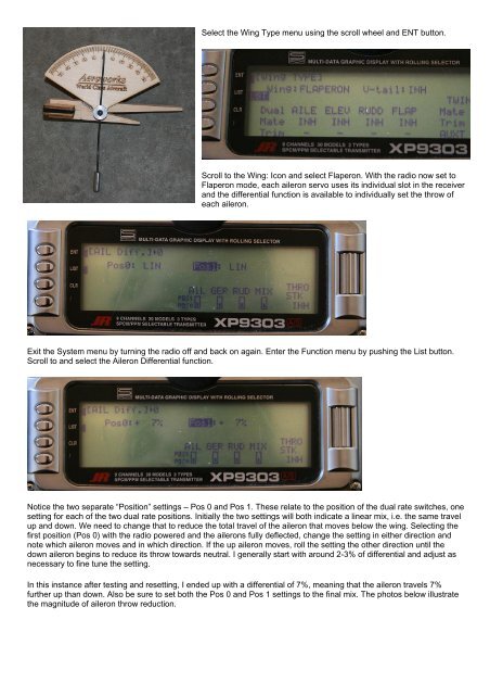
Aileron DifferentialIf you think back to the trimming process outlined in the companion print article, by the time you’ve reached the need foraileron differential you already set both the CG and the thrust line of <strong>your</strong> model. As a refresher on aileron differentialI’ve included an excerpt from the print article below:“With the CG and thrust lines set, the next step is to make <strong>your</strong> model roll axially as if on a string by adjusting ailerondifferential. Barring any manufacturer specific direction, I generally recommend symmetrical throws as a good startingpoint. Some models, however, just won’t roll axially with symmetrical throws, and aileron differential is a great solution.I find the best way to test for axial roll characteristics is on vertical down-lines. With the throttle closed, establish adown-line and begin a constant roll. Note any barreling of the roll. Perfectly trimmed, the model should maintain astraight vertical down-line while rolling axially as if on a taught string. To correct for a barreled roll, start by reducingthe throw of the down aileron for that roll direction incrementally. I find that small changes in differential - often just acouple of degrees, are enough. Don’t forget to also test the roll in the opposite rolling direction, as it isn’t uncommonfor the two rolling directions to be slightly different.Note, I recommend testing for axial rolls only on vertical downlines - not on level lines. The reason for this is that onvertical down lines there is no “up” or “down.” Any non-axial rolling tendencies noticed on the vertical line relate only tothe rolling characteristics of the model, not the effects of gravity. Also, unlike upright level flight where the wing is at aslightly positive or negative AOA, vertical lines are close to zero AOA. At zero AOA, we can truly assess whether themodel needs differential to roll axially.”So the burning question – how do we modify the aileron throws to allow differential? Different radio manufacturers giveyou different tools to accomplish this, so we’ll look at two of the more common techniques available.Before we do, however, I’d like to show you a really cool tool we’ll use to precisely measure control throw – the throwmeter.Several different versions are available, but the AeroWorks throw meter is one of my favorites. It uses a large clothespinas its attachment device which may be unacceptable for smaller models, but is ideal for the larger models I prefer.We’ll use the throw meter for measuring aileron differential, but it is also a great tool for setting dual rates and measuringcontrol throw in general.If an airplane displays the need for aileron differential, the most common corrective change is a reduction of the “down’aileron, i.e. reducing the throw of the throw on each aileron as it travels below the wing when viewed from above themodel. Once you establish the need for differential to make <strong>your</strong> model roll axially, you need to decide which of thefollowing two techniques will work with <strong>your</strong> transmitter setup – electronic differential or end point adjustment. The JR9303 allows differential while using dual aileron servos as flaperons, so that’s the first technique I’ll cover. The Futaba9CAP inhibits the differential function during flaperon use, so we’ll focus the end point technique for that radio.JR 9303 – Aileron Differential FunctionThe first step in setting up differential with the 9303 is to ensure that you are using the Flaperon mode to control the twoindividual aileron servos. Enter the system menu by holding the ENT button as you turn on the radio.
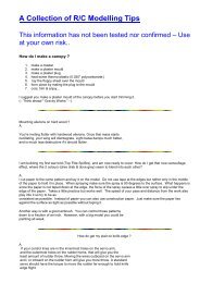
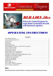
Select the Wing Type menu using the scroll wheel and ENT button.Scroll to the Wing: Icon and select Flaperon. With the radio now set toFlaperon mode, each aileron servo uses its individual slot in the receiverand the differential function is available to individually set the throw ofeach aileron.Exit the System menu by turning the radio off and back on again. Enter the Function menu by pushing the List button.Scroll to and select the Aileron Differential function.Notice the two separate “Position” settings – Pos 0 and Pos 1. These relate to the position of the dual rate switches, onesetting for each of the two dual rate positions. Initially the two settings will both indicate a linear mix, i.e. the same travelup and down. We need to change that to reduce the total travel of the aileron that moves below the wing. Selecting thefirst position (Pos 0) with the radio powered and the ailerons fully deflected, change the setting in either direction andnote which aileron moves and in which direction. If the up aileron moves, roll the setting the other direction until thedown aileron begins to reduce its throw towards neutral. I generally start with around 2-3% of differential and adjust asnecessary to fine tune the setting.In this instance after testing and resetting, I ended up with a differential of 7%, meaning that the aileron travels 7%further up than down. Also be sure to set both the Pos 0 and Pos 1 settings to the final mix. The photos below illustratethe magnitude of aileron throw reduction.