Air Quality Control Systems and Components - Hitachi Power ...
Air Quality Control Systems and Components - Hitachi Power ...
Air Quality Control Systems and Components - Hitachi Power ...
- No tags were found...

Create successful ePaper yourself
Turn your PDF publications into a flip-book with our unique Google optimized e-Paper software.
<strong>Hitachi</strong> <strong>Power</strong> EuropeFrom Coal to Electricity<strong>Power</strong> generation diagram in a typical coal power plant Before injection into the furnace, the raw coal is crushed to a fine dust in coal mills. Combustion of the pulverized fuel in the steam generator furnace produces flue gases withtemperatures up to 1,450°C. The heat released is used to generate steam under high pressure<strong>and</strong> temperatures. The steam is directed to a turbine where it impinges on the blade wheels <strong>and</strong> turns the turbine shaft.An attached generator generates the electricity.ContentsExperience <strong>and</strong> Competencein Environmental Engineering 4Flue Gas Desulphurization 6Nitrogen Oxygen Reduction(DeNO X ) 8Mercury Reduction 10SCR for Lignite <strong>and</strong> Dry Lignite 11CO 2 Capture 12Integration of the DownstreamFlue Gas Scrubber (PCC) 14Example:Retrofitting <strong>Power</strong> Plants 15 The nitrogen oxides in the flue gas react in the DeNOx facility by means of catalysts –nitrogen <strong>and</strong> water vapour arise, as a result. Ash particles adhere to electrically charged surfaces in the electrostatic precipitator.They are rapped <strong>and</strong> removed from the flue gas. In the flue gas desulphurization plant (FGD), lime slurry or limestone flour suspension binds thesulphur dioxide out of the flue gas. The end product is gypsum.2
Technology Leader with Excellent ReferencesWhether as a plant constructor or as a supplier of key components, <strong>Hitachi</strong> <strong>Power</strong> EuropeGmbH (HPE) is one of the technology <strong>and</strong> market leaders in fossil-fired power plants.The company – a subsidiary of <strong>Hitachi</strong>, Ltd. – has its head offices in Duisburg. HPE designs<strong>and</strong> builds not only power plants but also supplies all the key components such as utilitysteam generators, environmental engineering, turbines <strong>and</strong> pulverizers. In so doing, HPE canturn back to a track record going back over many years, an extensive list of references <strong>and</strong>to the outst<strong>and</strong>ing know-how of its workforce. Within the <strong>Hitachi</strong> Group, HPE is responsiblefor the markets in Europe, Africa, Russia (incl. Belarus) <strong>and</strong> India. <strong>Hitachi</strong> <strong>Power</strong> Europe GmbH, Duisburg Babcock Fertigungszentrum GmbH, Oberhausen BGR Boilers Private Ltd., Chennai Donges SteelTec GmbH, Darmstadt1 2647 <strong>Hitachi</strong> <strong>Power</strong> Africa (Pty) Ltd., Johannesburg <strong>Hitachi</strong> <strong>Power</strong> Europe Service GmbH, Duisburg Meeraner Dampfkesselbau GmbH, Meerane35<strong>Air</strong> <strong>Quality</strong> <strong>Control</strong> <strong>Systems</strong> 3
Experience <strong>and</strong> Competence in Environmental EngineeringAmple References<strong>Hitachi</strong> <strong>Power</strong> Europe GmbH (HPE) has both intelligent <strong>and</strong> environmentally compatibleair quality control systems. Our staff insert air quality control systems downstreamof fossil-fired power plants either as an overall concept or as single components(desulphurization, de-nitrification, dust collection). Their extent can be individuallyadapted depending on preference <strong>and</strong> requirement. Our references attest to the fact thatHPE not only fulfills customer preferences but also repeatedly sets raised st<strong>and</strong>ards forthe environment.Project Customer Product Capacity Fuel CommissioningFlue gas rateElectrical powerPrecipitation rateChvaletice 1, 2, 3, 4 2,066,400 Nm³/h 1997Czech RepublicCEZ a.s.FGD200 x 4 MWel95% Lignite1998VresovaCzech RepublicKrabi 1Thail<strong>and</strong>Kozienice #9, 10Pol<strong>and</strong>Kozienice 4–8Pol<strong>and</strong>Sioux 1, 2USACoffeen 1, 2USADuck Creek 1USASokolovskáuhelná a.s.EGATKozienice S.A.Kozienice S.A.AmerenAmerenAmerenFGD 1,510,000 Nm³/h 87% Lignite 2002FGDFGDFGDFGDFGDFGD1,004,000 Nm³/h300 MWel2,066,400 Nm³/h500 MWel3,480,000 Nm³/h(200 x 4 MWel equiv.)2,005,367 Nm³/h2 x 535 MWel1,464,395 Nm³/h2 x 360 MWel1,627,239 Nm³/h444 MWelAbono 2 Hidroelectrica 2,225,780 Nm³/hSpaindel Cantabrico S.A.FGD556 MWelSoto 3 Hidroelectrica 1,330,576 Nm³/hSpaindel Cantabrico S.A.FGD350 MWelLa Robla 2 Unión Fenosa 1,500,000 Nm³/hSpainGeneración S.A.FGD350 MWel90% Oil 200494.8% Coal 200594% Coal 200799% Coal 200899% Coal 200999% Coal 200890% Coal 200890% Coal 200895% Coal 2008Sines 1, 2, 3, 4 1,160,000 Nm³/h 2008PortugalCPPE/EDPFGD4 x 314 MWel90% Coal2009Narcea 3 Unión Fenosa 1,500,000 Nm³/hSpainGeneración S.A.FGD350 MWelWalsumGermanyEvonik/EVNFGD1,800,000 Nm³/h790 MWel95% Coal 200998% Coal 2013Westfalen 1,900,000 Nm³/h 2013/2014GermanyRWEFGD2 x 820 MWel98% Coal(Scheduled)Wilhelmshaven Electrabel/ 1,800,000 Nm³/h 2014GermanyGDF SuezFGD790 MWel99% Coal(Scheduled)Eemshaven 1,900,000 Nm³/h 2014Netherl<strong>and</strong>sRWEFGD2 x 820 MWel98% Coal(Scheduled)Rotterdam Electrabel/ 1,800,000 Nm³/hNetherl<strong>and</strong>sGDF SuezFGD790 MWel99% Coal 2013References of HPE <strong>and</strong> <strong>Hitachi</strong> <strong>Power</strong> Group, as of: June 20134
Constant RefinementsIn keeping with the requirements placed on the environment, the technology of the airquality control systems is constantly refined. The trend in requirements put on air qualitycontrol systems is reflected in the development of emission st<strong>and</strong>ards in Europe.Status of emission st<strong>and</strong>ards in Europe400350Emission st<strong>and</strong>ard300250200150100500SO x(mg/Nm³)NO x(mg/Nm³)Dust(/10 mg/Nm³)HCI(/10 mg/Nm³)HF(/100 mg/Nm³)400 200 30 – –200 200* 20 10 (17th. BImSchV) 1 (17th. BImSchV)100 80 10 8 1■ EU St<strong>and</strong>ard■ 13th. BImSchV■ Actual St<strong>and</strong>ard Germany* 100 as a yearly average0.050.0450.04Emission st<strong>and</strong>ard0.0350.030.0250.020.0150.010.0050Hg(mg/Nm³)Cd + Tl(mg/Nm³)Other HM(*10 mg/Nm³)Dioxins <strong>and</strong> Furans(*10 ng/Nm³)0.03 0.05 0.5 0.10.03 0.05 0.5 0.1■ 13th. BImSchV■ Actual St<strong>and</strong>ard Germany<strong>Air</strong> <strong>Quality</strong> <strong>Control</strong> <strong>Systems</strong> 5
Flue Gas DesulphurizationWell within the St<strong>and</strong>ardsHPE makes use of unhydrated lime <strong>and</strong> the limestone gypsum process for flue gasdesulphurization in power plants. For these technologies we have proven specialists whocan look back on a long track record in flue gas desulphurization.Thanks to these technologies all the emission st<strong>and</strong>ards possibly affected by the flue gasscrubber are reliably kept to or fall well within them. Gypsum can be recovered as the endproduct for further industrial utilization. In line with customer preferences, <strong>Hitachi</strong> <strong>Power</strong> Europeeven supplies the flue gas desulphurization systems (FGD) on a turnkey basis. Finally, thegypsum that arises is sent to the manufacturing industry.Limestone gypsum processOn account of its simplicity, the limestone gypsum process has proved its worth across theworld in flue gas desulphurization. This process involves sulphur dioxide (SO 2 ), hydrogenchloride (HCl) <strong>and</strong> hydrogen fluoride (HF) being precipitated in an alkaline scrubbing liquid.The limestone-induced absorption gives rise to a high-grade gypsum product, which isnoticeable for its degree of whiteness. If required by the customer, the unhydrated lime processcan also be used.Separate stackWith the cleaning over, the flue gas can be emitted directly to the atmosphere via the coolingtower or separate stack on the absorber. Which of these two processes is more cost-efficientis calculated on the basis of stack height <strong>and</strong> number of power plant units. In matters ofexisting plant refurbishment, use can be made either of the original flue gas path or a mountedstack.Diagram of FGD processCooling towerFlue gasEl.precipitatorAbsorberAsh siloOxidation airAbsorber residueemptying tankProcess waterPulverized limestonePulverizedlimestone siloTo waste watertreatmentWaste waterGypsumTo gypsumstorage area6
HPE Absorber Absorber inletFlue gas Absorber sump (Tank)Normal residence time 4 minutes inGermany, but it can be flexibly designed. Spray nozzlesUp-<strong>and</strong>-down spray nozzles; mostly hollowcone, only near the wall maybe change tofull cone. Spray levelsNumber of spray levels depends on fuel.For inter national coal <strong>and</strong> emissionrequirements as requested in Germany:4 levels plus space for retrofit of 5th level. Mist eliminatorDepending on the allowable dropletcontent downstream of the mist eliminator2 or 3 stages. Absorber outletHorizontal or vertical outlet will be selecteddepending on downstream equipment.Intelligent TechnologyThe flue gas enters the lower part of the HPE absorber <strong>and</strong> ascends through the absorptionsection. Intelligent technology ensures that the number of nozzle levels of the contact zone<strong>and</strong> positioning of their nozzles are adjusted to the desired absorber collecting efficiency.Up-to-the-minute computations of flue gas entry angle <strong>and</strong> speed make it possible forturbulence to be kept well down inside the absorber. A large <strong>and</strong> a fine droplet separatorretain the fine droplets in the flue gas before the cleaned gas leaves the absorber. The actualtransition from pollutant gas to liquid occurs in an intensively intermixed gas / liquid contactzone.<strong>Air</strong> <strong>Quality</strong> <strong>Control</strong> <strong>Systems</strong> 7
Nitrogen Oxide Reduction (DeNO X )Coal <strong>Power</strong> PlantWalsum 10Reduced to a MinimumThe major elementsof a DeNO X system are:■ Ammonia / ammonium hydroxidestorage <strong>and</strong> supply■ Ammonia / ammonium hydroxidespray–in <strong>and</strong> mixer systems■ DeNO X reactor with rectifier<strong>and</strong> sootblower■ CatalystsIn the case of secondary measures to reduce nitrogen oxides (DeNO X ), progressive plantconstructors, such as <strong>Hitachi</strong> <strong>Power</strong> Europe, make use of selective catalytic reduction (SCR).This up-to-date process ensures that nitrogen emissions are cut to a minimum.Arising from a combination of ammonia <strong>and</strong> precipitated nitrogen oxide are the air constituentsof nitrogen <strong>and</strong> water vapor. Almost complete removal occurs of the nitrogen oxides generatedduring combustion.In modern plants the SCR technology is installed upstream of the air heater, although underapplications seldom met with it can be used downstream of the flue gas scrubber. Deploymentupstream of the air heater is tantamount to optimal integration into the overall process of apower plant from the process <strong>and</strong> resources-conservation angle. In both instances,considerable allowance is made for <strong>Hitachi</strong> know-how - as both a boiler manufacturer <strong>and</strong>FGD plant constructor – in incorporating SCR technology into the power plant process.8
Efficient CatalystsThe heart of the SCR process is the catalyst. Plate or honeycomb catalysts used forDeNO X systems are available. <strong>Hitachi</strong> <strong>Power</strong> Europe DeNO X systems are compatible with allcatalysts available on the markets. For each system an individual check is made as towhich catalyst results in the most efficient <strong>and</strong> most favorable system concept.Titanium dioxide-based catalysts with vanadium molybdenum <strong>and</strong> tungsten oxides areconsidered throughout the world to be state-of-the-art.The DeNO X reactor is for firmly anchoring the catalyst modules. In keeping with therequirements placed on nitrogen oxide precipitation, the number of levels is established inclose cooperation with the operator when the order is being drawn up. Catalyst modules canbe mounted on these levels. A number of them are equipped with modules <strong>and</strong> the othersserve as st<strong>and</strong>by levels for any subsequent installation of additional catalyst elements.To ensure a preferably even approach flow to the catalysts, a flow rectifier is fitted above thefirst catalyst level.Flue gas flows downwards through the reactor. Dust deposits on the catalyst modules areregularly removed layer-by–layer with the aid of steam-operated sootblowers. Sonic hornscan be fitted as an alternative to sootblowers.DeNO X reactor<strong>Air</strong> <strong>Quality</strong> <strong>Control</strong> <strong>Systems</strong> 9
Mercury ReductionAlways One Step AheadMercury reduction (Hg reduction) is becoming ever more important in air quality controlsystems. A precipitation rate of up to 80 % is needed for adherence to the ongoingdaily mean of 0,03 mg/Nm³. Various tests undertaken at power plants have confirmedthat HPE's existing system components keep to this st<strong>and</strong>ard.HPE, however, not only wants to keep up with things as they are but also to be one stepahead. That is why the engineers of <strong>Hitachi</strong>, Ltd., our parent company, are working on aprecipitation process in which the catalyst oxidizes the mercury (new catalyst). The mercurycan then be precipitated in the absorber.This process has a distinct advantage in that with low-chloride coals the new catalyst supportsoxidation of metallic mercury into ionic mercury. This oxidation rate rise is of significancesince it is precisely this oxidation process which is needed for mercury precipitation. It wasnoticed from examinations of the gaseous mercury loads in flue gases that a rising chloridecontent in the coal was accompanied by a comparative increase of the mercury gaseouschloride compound in the flue gas.The only operational findings available at the moments relate to the combustion of bituminouscoal with a low CI content. The expectation from using this catalyst is for the Hg oxidationto increase to over 80 % with the SO 2 -to-SO 3 conversion continuing to remain under 0.5%.Characteristics of new SCR CatalystSub-bituminous coalBituminous coal (eastern)100New catalystMercury oxidation (%)80604020Conventional catalystWithout catalyst020 40 60 80 100HCI concentration (ppm)10
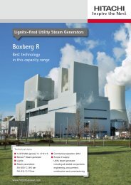
SCR for Lignite <strong>and</strong> Dry LigniteLignite <strong>Power</strong> PlantBoxberg (Unit Q +R)Ideally Prepared to Face New Dem<strong>and</strong>sUp to now, secondary nitrogen oxide reduction measures (SCR technology) have onlybeen necessary to meet the prescribed low nitrogen oxide emissions for pit coal.But from 2102 revised st<strong>and</strong>ards will, in fact, apply generally to all coal-fired power plants.In-furnace control measures are not sufficient to meet the requirements of the “13th BimSchV”(German Immission Protection Ordinance) for lignite of a max. 100 mg/m³ of NO X emissions.<strong>Hitachi</strong> <strong>Power</strong> Europe is ideally prepared to face this fact. For lignite, the air quality controlsystem experts are making use of the pit coal-proven SCR technology – one which willundoubtedly adhere to the revised st<strong>and</strong>ards. Even so, examinations are needed into theimpact of the lignite fuel on the catalyst – something which <strong>Hitachi</strong> <strong>Power</strong> Europe is collectivelyundertaking with a major power operator. It is to be found out if the differing pit coalconstituents give rise to any catalyst abrasion or ageing.18161412108642Gas Speed0 Velocity (m/s)Graphics animation of a CFD analysis(CFD = Computational Fluid Dynamics)<strong>Air</strong> <strong>Quality</strong> <strong>Control</strong> <strong>Systems</strong> 11
CO 2 CapturePost-combustion Capture (PCC)HPE is developing technologies for carbon (CO 2 ) capture <strong>and</strong> storage – CCS – for electricitygeneration from fossil fuels. The company is backing two processes: post-combustioncapture (PCC) <strong>and</strong> the oxyfuel technology. They are being tested <strong>and</strong> pilot-scaled forcommercial use at power plants.For the PCC process, HPE has completed a pilot facility (see diagram on the left) for CO 2capture based on a gas scrubber. It will be set up in cooperation with energy suppliers at apower plant site in the Netherl<strong>and</strong>s in mid-2010 <strong>and</strong> be subject to tests involving variousscrubbing agents up to 2015. One of the pilot plant's assets is its transportability which allowsit to be deployed under various conditions. Moreover, it is not subject to any specificscrubbing / amine solution; the operator is free to use the agent of his choice. In conjunctionwith German operators <strong>and</strong> universities, HPE is also supporting the construction of a secondmobile pilot plant for testing CO 2 scrubbing agents – which are not subject to protectiverights – at a power plant in Duisburg.Thanks to joint competence within the <strong>Hitachi</strong> Group (power plant boiler, turbine, air qualitycontrol <strong>and</strong> compaction), HPE has developed an overall plant technology which for futureplants cuts efficiency losses from CO 2 capture to under 8 percentage points as against11 – 14 percentage points with today's scrubbing agents <strong>and</strong> without thermal integration.Present technology scaling is needed for CCS plants to be commercially realized. This isalready the case on the demo plant scale. In fact, <strong>Hitachi</strong> project realization is close on h<strong>and</strong>in Canada <strong>and</strong> the USA. An additional required enlargement of the components – as thefinal step to complete CO 2 capture in utility power plants – is being looked into in detailunder ongoing projects.Thermal integration of the CO 2 flue gas scrubber into thepower plant operationCommercial realization of theCO 2 flue gas scrubberCO 2CO 2CompactionCO 2Heat integrationCoolingEl. powerFuel<strong>Air</strong><strong>Air</strong>/fluegas systemFlue gasHeatWater/steamcirculation,Turbine,GeneratorFlue gasCondensateSteamFlue gascleaning &CO 2 captureCleanedflue gasEl. power105 m70 mHeat integration12
Oxyfuel TechnologyExaminations have been conducted both inside <strong>and</strong> outside the Group for many years nowinto oxyfuel technology on the pilot plant scale by <strong>Hitachi</strong> <strong>Power</strong> Europe in associationwith both universities <strong>and</strong> partners.Oxyfuel Process Flow DiagramSteam circulation<strong>Air</strong>separationSteam generator DeNO unit ASUx N 2Heat discharge HeatCO 2displacement compression<strong>Air</strong>systemCO 2O 2Draft fanElectrostaticCoalFGDDrying <strong>and</strong>precipitatorafter-cleaningFlue gas recycleAshSulphurH 2 OH 2 OH 2 OValuable findings have been collected into the operational basics <strong>and</strong> design software fora variety of components has been adapted to the revised requirements.These findings have been made use of, for instance, in designing a new DS ® -T burner forfiring dry fuels. This burner was successfully tested in a 30 MWth experimental combustionfacility under air combustion conditions in 2009 / 2010. The fuels used were dry lignite,bituminous coal <strong>and</strong> dust-like biomass. The fact that stable combustion was maintained underadherence to the relevant emission data is proof of the high flexibility of HPE's technology.The second step saw this burner – under a technology partnership scheme with energysupplier Vattenfall – being successfully tested in the “Schwarze Pumpe” oyxyfuel pilot plantup to April 2010 <strong>and</strong> placed into service. Combustion optimization is now proceeding.The findings will flow into the design of an oxyfuel demonstration plant which is currentlybeing planned.In conjunction with sister companies, HPE also validates the design fundamentals <strong>and</strong>materials / catalyst materials for other major components, such as the desulphurization<strong>and</strong> denitrification equipment of oxyfuel flue gases, <strong>and</strong> materials for the boiler.Flame images of the burner testswith dry lignite (top), biomass (center)<strong>and</strong> bituminous coal (bottom)<strong>Air</strong> <strong>Quality</strong> <strong>Control</strong> <strong>Systems</strong> 13
Post Carbon Capture Plant Integration (PCC)Highest Efficiencies with PCCImplementation of Post Carbon Capture Plants (CCS) needs proper PCC process integrationinto the conventional part of a power plant.<strong>Hitachi</strong>, as supplier <strong>and</strong> service provider of the main plant components such as steamgenerator, steam turbine generator set, BOP equipment <strong>and</strong> air quality management systems,is able to develop these integration concepts <strong>and</strong> minimize efficiency loss due to PCC processintegration.From the efforts put in by our experienced engineers for all disciplines, <strong>Hitachi</strong> guaranteesbest efficiencies for power plants with carbon dioxide sequestration. Also for existingplants, our teams evaluate the impact of PCC integration on all major components <strong>and</strong><strong>Hitachi</strong> steam turbineof maximum reliabilitydevelop strategies <strong>and</strong> retrofit measures.Influence of PCC on steam turbinePCC plant integration has a major impact on the steam turbine <strong>and</strong> its design in case of100% flue gas treatment. For new power plants, the requirements of a PCC plant should beconsidered when drafting the steam turbine concept. <strong>Hitachi</strong>, as a supplier of steam turbinegenerator sets, is in a position to supply tailor-made steam turbine concepts optimizedfor PCC plant integration. With our knowledge, experience <strong>and</strong> help of modern software tools,<strong>Hitachi</strong> intends to evaluate the impact of all PCC plant operation modes <strong>and</strong> optimizethe steam turbine so as to obtain a reliable high efficiency under all load conditions.Numeric analysis of turbine bladesfor PCC integration800 MW steam turbine14
Example: Retrofitting <strong>Power</strong> PlantsA Truly Clean MatterWhether it is a new building or retrofitting, <strong>Hitachi</strong> <strong>Power</strong> Europe specialists have both theknow-how <strong>and</strong> the required products to substantially cut emissions in fossil-fired powerplants with the aid of up-to-the-minute environmental engineering.The newly built flue gasdesulphurization facilityat the Narcea power plantThe most recent example concerns the steps to upgrade the two “La Robla 2” <strong>and</strong>“Narcea 3” pit coal power plants. Both the 305 MW units in Asturia (northern Spain) are over25 years old. The technology used was no longer adequate to comply with the strictenvironmental protection regulations (st<strong>and</strong>ards for emissions of nitrogen oxides, sulphurdioxide <strong>and</strong> dusts) within the European Union. <strong>Hitachi</strong> <strong>Power</strong> Europe was commissioned by“Union Fenosa Generación” – the 3rd largest Spanish energy supplier – with designing <strong>and</strong>constructing a flue gas desulphurization system (FGD) for both the power plant sites.HPE was also given the task of modifying the pulverized fuel burners to achieve firingsystem optimization of both boilers.Emissions from La Robla / Narcea (in mg/Nm 3 )La RoblaNarceaNO xSO 2 < 230*< 600NO x~ 1,200< 860~ 1,500SO 24,000*< 200*4,600*before upgrading after upgrading * dry at 6% O 2HPE h<strong>and</strong>led the flue gas desulphurization systems in consortium with <strong>Hitachi</strong> subsidiary<strong>Hitachi</strong>-BHK <strong>and</strong> the Spanish Cobra company. The burners come from BabcockFertigungszentrum GmbH – a subsidiary of <strong>Hitachi</strong> <strong>Power</strong> Europe. The system parts – fromburners <strong>and</strong> fans to meter-high dampers – were manufactured, for instance, in Germany,Pol<strong>and</strong>, Denmark <strong>and</strong> Irel<strong>and</strong>. The components were delivered just-in-time for immediateassembly purposes.The <strong>Hitachi</strong> <strong>Power</strong> Europe team h<strong>and</strong>ed over the systems to the customer as agreed to atthe end of 2008 <strong>and</strong> in mid-2009. The success can be measured. Refurbishment wasfollowed by a substantial cut in flue gas emissions – by 60 % in the case of nitrogen oxides(NO X ), 95 %+ in the case of sulphur dioxide <strong>and</strong> 50 %+ for the dust content.<strong>Air</strong> <strong>Quality</strong> <strong>Control</strong> <strong>Systems</strong> 15
© <strong>Hitachi</strong> <strong>Power</strong> Europe GmbH /06.2013/Printed on chlorine-free bleached paper<strong>Hitachi</strong> <strong>Power</strong> Europe GmbHSchifferstraße 8047059 Duisburg, GermanyPhone +49.203.8038-0Fax +49.203.8038-1809infobox@hitachi-power.comwww.hitachi-power.com