TMdrive®-10e2 Product Application Guide - Tmeic.com
TMdrive®-10e2 Product Application Guide - Tmeic.com
TMdrive®-10e2 Product Application Guide - Tmeic.com

Create successful ePaper yourself
Turn your PDF publications into a flip-book with our unique Google optimized e-Paper software.
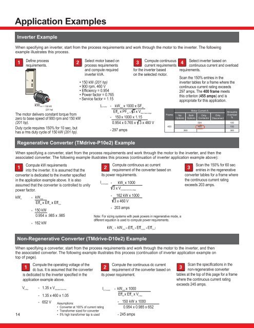
<strong>Application</strong> ExamplesInverter ExampleWhen specifying an inverter, start from the process requirements and work through the motor to the inverter. The followingexample illustrates this process.1Define processSelect motor based onCompute continuous23requirements.process requirementscurrent requirements4and <strong>com</strong>pute requiredinverter kVA.for the inverter basedon the selected motor.Regenerative Converter (TMdrive-P<strong>10e2</strong>) ExampleWhen specifying a converter, start from the process requirements and work through the motor to the inverter, and then theassociated converter. The following example illustrates this process (continuation of inverter application example above):Compute kW requirementsCompute continuous ac currentScan the 150% for 60 sec1 23into the inverter. It is assumed that therequirement of the converter based onentries in the regenerativeconverter is dedicated to the inverter specified its power requirements.converter tables for a frame wherein the application example above. It is alsothe continuous current ratingI = kW dcx 1000assumed that the converter is controlled to unityac Converterexceeds 203 amps.power factor.3 x V Converter line-to-line voltagekW dc= kW ShaftEff Mtrx Eff Invx Eff Conv14kW Shaft = 150 kW(201 hp)The motor delivers constant torque fromzero to base speed of 900 rpm and 150 kW(201 hp).Duty cycle requires 150% for 10 sec, buthas a rms duty cycle of 150 kW (201 hp).= 150 kW0.954 x .985 x .985= 162 kW= 162 kW x 10003 x 460 V= 203 ampsNote: For sizing systems with peak powers in regenerative mode, adifferent equation is used to <strong>com</strong>pute power requirements.kW dc= kW Shaftx (Eff Mtr x Eff Inverter x Eff Conv )Non-Regenerative Converter (TMdrive-D<strong>10e2</strong>) ExampleWhen specifying a converter, start from the process requirements and work through the motor to the inverter, and thenthe associated converter. The following example illustrates this process (continuation of inverter application example ontop of page).Compute the operating voltage of theCompute the continuous dc current1 23dc bus. It is assumed that the converterrequirement of the converter based onis dedicated to the inverter specified in the its power requirement.application example above.V dc Bus= 1.35 x V Converter line-to-line= 1.35 x 460 x 1.05= 652 V• 150 kW (201 hp)• 900 rpm, 460 V• Efficiency = 0.954• Power factor = 0.765• Service factor = 1.15Assumptions:• Converter at 100% of current rating• Transformer sized for converter• 5% high transformer tap is usedIac Inverter = kW Shaftx 1000 x SF MtrEff Mtrx PF Mtr x 3 x V Motor rated voltage= 150 x 1000 x 1.150.954 x 0.765 x 3 x 460 V= 297 ampsI dc Converter= kW Shaftx 1000Eff Mtrx Eff Invx V dc Bus= 150 kW x 10000.954 x 0.985 x 652= 245 ampsFrame400Select inverter based oncontinuous current and overloadrequirements.Scan the 150% entries in theinverter tables for a frame where thecontinuous current rating exceeds297 amps. The 400 frame meetsthis criterion (455 amps) and isappropriate for this application.NoOptionsMotor Current ABothOptionsOnlyContactorOnlyDisconnectAllowableOverload%504 100455 150263 300Scan the specifications in thenon-regenerative convertertables at the top of this page for a framewhere the continuous current ratingexceeds 245 amps.