TMdrive®-10e2 Product Application Guide - Tmeic.com
TMdrive®-10e2 Product Application Guide - Tmeic.com
TMdrive®-10e2 Product Application Guide - Tmeic.com

Create successful ePaper yourself
Turn your PDF publications into a flip-book with our unique Google optimized e-Paper software.
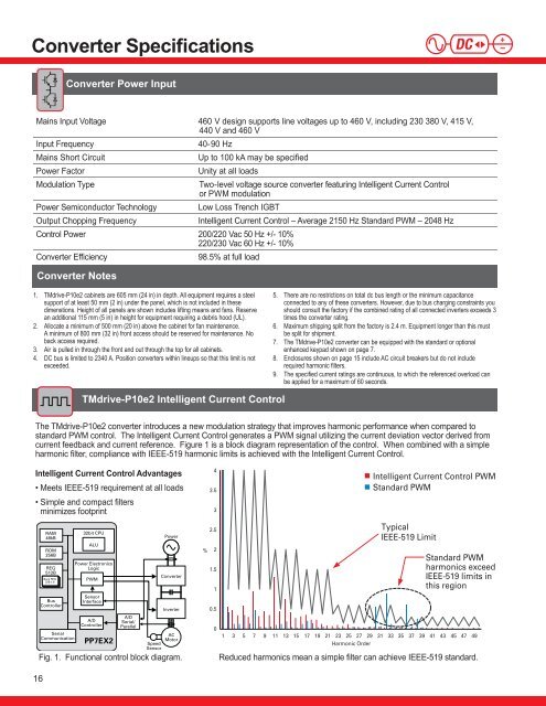
Converter SpecificationsConverter Power InputMains Input Voltage 460 V design supports line voltages up to 460 V, including 230 380 V, 415 V,440 V and 460 VInput Frequency40-90 HzMains Short CircuitUp to 100 kA may be specifiedPower FactorUnity at all loadsModulation TypeTwo-level voltage source converter featuring Intelligent Current Controlor PWM modulationPower Semiconductor TechnologyLow Loss Trench IGBTOutput Chopping FrequencyIntelligent Current Control – Average 2150 Hz Standard PWM – 2048 HzControl Power 200/220 Vac 50 Hz +/- 10%220/230 Vac 60 Hz +/- 10%Converter Efficiency98.5% at full loadConverter Notes1. TMdrive-P<strong>10e2</strong> cabinets are 605 mm (24 in) in depth. All equipment requires a steelsupport of at least 50 mm (2 in) under the panel, which is not included in thesedimenstions. Height of all panels are shown includes lifting means and fans. Reservean additional 115 mm (5 in) in height for equipment requiring a debris hood (UL).2. Allocate a minimum of 500 mm (20 in) above the cabinet for fan maintenance.A minimum of 800 mm (32 in) front access should be reserved for maintenance. Noback access required.3. Air is pulled in through the front and out through the top for all cabinets.4. DC bus is limited to 2340 A. Position converters within lineups so that this limit is notexceeded.5. There are no restrictions on total dc bus length or the minimum capacitanceconnected to any of these converters. However, due to bus charging constraints youshould consult the factory if the <strong>com</strong>bined rating of all connected inverters exceeds 3times the converter rating.6. Maximum shipping split from the factory is 2.4 m. Equipment longer than this mustbe split for shipment.7. The TMdrive-P<strong>10e2</strong> converter can be equipped with the standard or optionalenhanced keypad shown on page 7.8. Enclosures shown on page 15 include AC circuit breakers but do not includerequired harmonic filters.9. The specified current ratings are continuous, to which the referenced overload canbe applied for a maximum of 60 seconds.TMdrive-P<strong>10e2</strong> Intelligent Current ControlThe TMdrive-P<strong>10e2</strong> converter introduces a new modulation strategy that improves harmonic performance when <strong>com</strong>pared tostandard PWM control. The Intelligent Current Control generates a PWM signal utilizing the current deviation vector derived fromcurrent feedback and current reference. Figure 1 is a block diagram representation of the control. When <strong>com</strong>bined with a simpleharmonic filter, <strong>com</strong>pliance with IEEE-519 harmonic limits is achieved with the Intelligent Current Control.Intelligent Current Control Advantages• Meets IEEE-519 requirement at all loads• Simple and <strong>com</strong>pact filtersminimizes footprintRAM48kBROM256BREG512BBank REG32B x 8BusControllerSerialCommunication32bit CPUALUPower ElectronicsLogicPWMSensorInterfaceA/DControllerPP7EX2A/DSerial/ParellelPowerConverterInverterACMotorSpeedSensorFig. 1. Functional control block diagram.%43.532.521.510.50Intelligent Current Control PWMStandard PWMTypicalIEEE-519 LimitStandard PWMharmonics exceedIEEE-519 limits inthis region1 3 5 7 9 11 13 15 17 19 21 23 25 27 29 31 33 35 37 39 41 43 45 47 49Harmonic OrderReduced harmonics mean a simple filter can achieve IEEE-519 standard.16