TMdrive®-10e2 Product Application Guide - Tmeic.com
TMdrive®-10e2 Product Application Guide - Tmeic.com
TMdrive®-10e2 Product Application Guide - Tmeic.com

You also want an ePaper? Increase the reach of your titles
YUMPU automatically turns print PDFs into web optimized ePapers that Google loves.
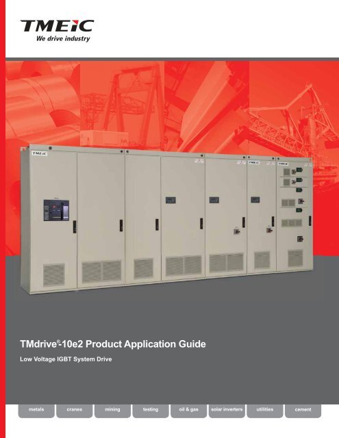
TMdrive ® -<strong>10e2</strong> <strong>Product</strong> <strong>Application</strong> <strong>Guide</strong>Low Voltage IGBT System Drivemetalscranesminingtestingoil & gassolar invertersutilitiescement
ACACACACACACACACACACTMdrive-<strong>10e2</strong> is anevolution in the familyof TMdrive ac systemdrives offering:• High reliabilityEthernetMELPLACControllersVVseries ControllerV Series ControllerLocal Monitoring/Control/Analysisnv ControllerMaster ControllersController (ISC)• Simple configurationand maintenance• Low cost of ownership• Compact designMELPLAC NetTMdriveMELVECTOSLINE-S20TMdriveLEOPACKTOSVERTVseries I/OTC-net I/OTMdriveLEOPACKTOSVERTnv ControllerField I/OEGDProfibus-DPTMdriveTOSVERTISBusDLAN+Profibus-DPTMdriveTOSVERTTOSLINE-S20Series Six Parallel I/O BusVersaMax and Genius ®LEOPACKLegacyDrive <strong>Product</strong>sLEOPACKLegacyDrive <strong>Product</strong>sTMdrive-<strong>10e2</strong>FeaturesBenefitsState-of-the-art microprocessors including floatingpoint calculation.Heat pipe cooling technology.The IGBT power bridges use heat pipe cooling technology.Microsoft ® Windows ® -based configuration.The TMdrive-Navigator is used to configure, install, andmaintain the TMdrive-<strong>10e2</strong> drives.LAN options:• TC-net I/O• Profibus-DP• DeviceNet• Modbus RTU• Ethernet Global Data (EGD)• ControlNetSafety features according to:• ISO 13849-1 (Category 3)• IEC 61800-5-2 (Safety Integration Level 2)Higher processing speed and <strong>com</strong>munications fornext generation control system.Per unit calculations are easy to understand.Reduces footprint and lowers audible noise.This technology saves valuable floor space and lowersthe required cooling-air flow, reducing the associatedaudible noise.World-class tool across all system drives.Flexible tool connectivity.Native Ethernet drive interface allows flexible point-topointTMdrive-Navigator <strong>com</strong>munication over controlLAN or even via your factory LAN.Multiple controller platforms supported.For virtually all controller platforms, these LAN optionsprovide seamless integration with the rest of yourfactory.Connectivity to legacy equipment.Existing equipment can be seamlessly integrated intonew systems.Risk is defined and analysis simplified according tothese standards.Integrated hardware removes the requirement forexternal <strong>com</strong>ponents to meet standards.The system is simplified and reliability improved.2
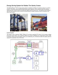
Bringing Reliable ControlTo System <strong>Application</strong>sIn the automation of container cranes, tightintegration between the system drive and thecontroller is a requirement. TMdrive-<strong>10e2</strong>’s<strong>com</strong>pact and efficient design together with amultitude of LAN options enhance yard and dockside crane productivity. The high-performancenetworks provide:• High-speed real-time control• Full automation with no operator• Remote connectivity for configuration andmonitoringCoordinated drive systems are an integral part ofmanufacturing processes in the metals industry.TMdrive-<strong>10e2</strong> system drives address all of theseapplications by providing:• High reliability, low maintenance, <strong>com</strong>pactdesign• Low voltage application from a few to hundredsof drives• High-speed <strong>com</strong>munication featuring robustcontrol and diagnostics• Strip transport or Auxiliary applications• Continuous or batch operationsIn the pulp and paper industry,uninterrupted operation is priority one.The robust design of the TMdrive–<strong>10e2</strong>heat pipe-cooled power bridges providessuperior reliability and maintainability forpaper mill applications.3
A Look InsideTwo-Level Phase Leg AssemblyThe cabinet style inverters havemodular two-level phase legassemblies, which weigh less than30 kg (66 lbs) each for easy handling.Each phase leg includes:• IGBTs with flyback diodes• Heat pipe assembly• IGBT gate driver circuit boardControl FunctionsThe primary control board performsseveral functions:• Speed and torque regulation• Sequencing• I/O mapping• Diagnostic data gatheringA mounting bracket is provided for anoptional LAN interface board.Harmonic FilterOptional advanced harmonicfilter panel can be integratedinto the lineup. The filteris arranged in an LCLconfiguration.1200 FrameConverterIn<strong>com</strong>ing Power(Main and Control)The converter in each lineupis fed 3-phase ac power. ACentry panels contain main ACbreaker and support both topand bottom entry. In addition,3-phase ac control power is fedto each converter and inverterin the lineup. A control powerdisconnect is provided in eachcabinet.I/O BoardAll TMdrive–<strong>10e2</strong> products includestandard I/O, which supports an encoder,24V dc and analog I/O. In addition,a resolver interface option can beprovided. All I/O’s are terminated to atwo-piece modular terminal block foreasy maintenance. Either screw or springterminal blocks can be provided.Motor Connectionsand OptionalOutput ContactorCabinet style inverters include bus tabsfor easy motor connection. Both JEM andNEMA drilling patterns are provided. Bottomcable entry is standard, and top entry isac<strong>com</strong>plished using an additional cablecabinet. A galvanized steel plate is providedin the bottom for termination of motor cableshields. An optional ac output contactor(shown) can be supplied.4
Heat Pipe CoolingTechnologyThe cabinet style inverters andregenerative converters use heatpipes to cool the IGBT powerswitches and capacitors. Thistechnology reduces the footprintof the power bridge as well asthe airflow requirements, savingvaluable floor space and reducingthe audible noise.Motor IsolationSwitchThe draw-out style inverterscan be equipped with optionalAC disconnect and cabinetstyle inverters with optionalDC disconnect to allow safeservicing of the motor.Reliable low voltage ac system drive technologydesigned to reduce cost of ownership:• Heat pipe cooling technology thatreduces the size of the power bridge and audiblenoise generated by the cooling fans• Draw-out style inverters for lowhp applications• Advanced IGBTs increase efficiency1200 FrameInverter400 FrameInverterDraw-OutStyle InvertersFrame15-100Frame150Frame250Draw-OutStyle InvertersFor applications up to 193 kW (259 hp), drawoutstyle inverters are available in a very<strong>com</strong>pact package. Draw-out inverters aremounted on heavy-duty slides with staggeredconnectors on the back that connect with thebus when slid into the cabinet. Motor cablesare terminated at a <strong>com</strong>mon terminal block inthe bottom of the cabinet. I/O and in<strong>com</strong>ing acpower are mounted on modular terminal blocksfor ease of maintenance.DC BusThe converter in eachlineup generates dc powerfor each of the inverters.The inverters then createvariable frequency acpower to control theinduction motors. This dcpower for the lineup isconveyed on a solid tinplatedcopper bus nearthe bottom of the cabinets.Equipment Safety CoversEquipment ships from the factory with steel safety covers. Thesecovers provide personal safety, even in the event that a cabinetdoor is opened, eliminating the need for door interlock devices.5
Flexible I/O InterfaceTMdrive-<strong>10e2</strong> features a flexible I/O system allowing a variety of I/O to connect directly to each inverter. Standard I/O shownbelow is always supplied. Additionally, either option unit A or B may be specified to extend I/O capability.Standard I/OLAN Interface OptionsDigital Inputs24 V dc10 mA• Quantity 2 for UVS (SIL 2)• Quantity 4 configurable mappingTC-net I/O• 8 words in/outDigital OutputsAnalog Inputs+/- 10 V dc4-20 mA24 V dc50 mAA/D• Quantity 2 for UVS (SIL 2)• Quantity 4 user defined• Open Collector• Quantity 1 configurable• Differential• 13-bit resolutionEthernet Global Data (EGD)Profibus-DPModbus RTU• 10 words in/out• 10 words in/out• 10 words in/outAnalog Outputs(Optional)Speed FeedbackResolver InputSpeed FeedbackEncoder InputSpeed TachFollower OutputD/AA+/- 10 V dc1 mASinCosSinCosB 25 mAZ12-24 V dcFdbk ExcitnABZSupply Excitn• Quantity 1 user defined• Non-Isolated• 10-bit resolution• Excitation frequency of 1 or 4 kHz• Source for resolvers isTamagawa:www.tamagawa-seiki.co.jp• A quad B with marker• Maximum frequency of 100 kHz• Differential or single-ended5 or 15 V dc• A quad B with marker• Maximum frequency of 100 kHzControlNetDeviceNetSafety Integrity• 10 words in/out• 4 words in, 10 words outTOSLINE-S20 and ISBus legacy LANs can also be supportedon request.Safety features according to IEC 618005-2 (Safety Integration Level2) and ISO 13849-1 (Category 3). Safety integrity level 2/category 3is insured by independent gate <strong>com</strong>mand lockout via two hardwareinputs; UVS1 and UVS2. In addition, when the optional output contactoris supplied it is also disabled by the UVS1 signal providing additionalprotection.MotorTemperatureFeedbackM• High-resolution torque motortemperature feedback• 1 kΩ positive temperaturecoefficient RTD or other sensorrequires selecting Option UnitGate Commandfrom controlUVS 215 VGate DriveDO_UVS2MOptionUVS1DO_UVS1Contactor Commandfrom controlOption I/O Unit AOption I/O Unit BDigital Inputs24 V dc10 mA• Adds Quantity 5 configurable• Relay or solid stateDigital Inputs24 V dc10 mA• Adds Quantity 6 configurable• Relay or solid stateDigital Outputs24 V dc• Adds Quantity 5 user defined• Relay (1 A) or solid state (70 mA)Digital Outputs24 V dc• Adds Quantity 6 user defined• Relay (1A) or solid state (70mA))Analog Inputs±10 V4-20 mAA/D• Adds one isolated channelAnalog Inputs±10 V4-20 mAA/D• Adds two isolated channelsAnalog OutputsD/A±10 V• Adds one isolated channelAnalog OutputsD/A±10 V• Adds two isolated channels1234567Option I/OUnit (A or B)CTRLANXIO1234567CTRLANXIOOption I/OUnit (A or B)Tool PortOption Unit Arequires oneslot tomount indraw-outenclosures.1234567CTRLANXIOOption I/OUnit ATool PortOption Unit Brequires twoslots tomount indraw-outenclosures.123456CTRLANXIOOption I/OUnit B6Cubicle Panel (600 mm) Cubicle Panel (800 mm) Draw-out Panel (Option A) Draw-out Panel (Option B)
Operator InterfacesCabinet Enclosure DisplaysThree-digit display alternates between speed and currentwhile running, or a fault code when there is an error.Standard DisplayLEDs give a quick indication of thestatus of the unit.LED IndicationReady On when the unit is readyto runRunning On when the unitis runningAlarm/Fault Blinking LED indicatesalarm condition, whilesolid LED indicates a faultDC Bus On when the DC Bus isDischarged dischargedRJ-45 Ethernet port is used forlocal tool connectionInterlock buttondisables the driveOptional Enhanced KeypadNavigationAllows adjustment of drive parameters from thefront of the equipment.ControlsAllow the equipment to be controlled in localmode from the front of the equipment.• Reset faults, reverse direction, inc./dec.speed, jog, run and stop are available.• Switch to local mode to allow operation at thiscontrol panel.Optional analog meters can be supplied in addition to either the standard or enhanced display.Standard inverter I/O includes meter driver outputs that are +/- 10 V with 10-bit resolution. Forcabinet style equipment, four meters are provided. For draw-out style, two meters are providedfor each inverter.Draw-out Enclosure DisplayLEDs give a quick indication of the status ofthe unit.LED IndicationDC Bus On when the DC BusDischarged is dischargedReadyRunningAlarm/FaultOn when the unit is readyto runOn when the unit is runningBlinking LED indicates alarmcondition, while solid LEDindicates a fault7
Control FunctionsThe TMdrive-<strong>10e2</strong> has a wide array of control functions to suit any application:I/O FunctionsSpeed/Torque Regulator Functions8Analog input conditioning:• Offset for each • Gain for each• Rollover protectionAnalog output conditioning:• Offset for each • Gain for each• Rollover protectionDigital position instrument with high-speedlatchesHigh-resolution motor temperature feedback:• Torque accuracy • Motor protectionDiagnostic and Protective Functions-Simulation mode for testing and training:• Motor simulator • Load simulatorHigh-speed data capture buffer:• Configurable trigger data capture (8 channels)• Fault data capture (90 channels, 7 faulthistory, Total 1MB of data)Protection:• Over speed• Speed error• Over frequency • Timed overcurrent• Cooling fan failure • Motor overheat• StallHeat Pipe TechnologyUsed In TMdrive-<strong>10e2</strong>This dramatic advance inpower bridge cooling designprovides:• Significant reduction in thefootprint of the power bridge• Lower audible noiseCondensate To Vapor1The thermal cycle starts with therefrigerant in condensate form at thebottom of the chill plate. IGBTs are mountedto the multi-channeled chill plate. The heatgenerated by these IGBTs vaporizes (heats) therefrigerant, moving it up through the chill plate tothe bottom of the condensing unit.-0Trq Comp --100 Outer regulator with 4 modes:• Speed• Torque• Speed with droop • Saturated speedwith torque controlCurrent limits:• di/dt• Inverting• Speed dependentAutomatic field adjustments:• Field weakening• Saturation <strong>com</strong>pensationFour forms of load <strong>com</strong>pensation:• Inertia• Friction• Windage• ImpactWizard functions:• Commissioning• Automatic motor control tuning• Automatic speed control tuningReference model:• Model following control to eliminatemechanical resonance problemsInner regulator with 3 modes:• Vector with speed feedback• Sensorless vector• Sensorless scaler (Volts/Hz)Configurable sequential functions:• Start• Alarm• Stop• Trip, etc.1 2 3Thermal CycleCondensing unit with several fins for the flow ofrefrigerantVapor To Condensate2The refrigerant cools while moving throughthe condensing unit. Cooling air is pulledvertically through the power bridge and then thecondensing unit by both convection and fansmounted in the top of the cabinet.The multi-channeled chill plate contains a CFC freerefrigerant which is practically non-toxic to humansand ozone friendly.IGBT power switches.3Return Of CondensateThe condensate (refrigerant in liquid form)returns to the bottom of the multi-channeled chillplate for the beginning of another thermal cycle.
TMdrive-Navigator –Simple Configuration & MaintenanceThe TMdrive-Navigator tool helps youmaintain TMEIC drives yourself.Engineers and technicians are empoweredto understand how the drive works andwhat the drive is doing. Any user caneasily access current drive expertise andknow-how.Desktop-like search technology links topicalsignal lists, block diagrams, help files, productdocumentation, change history, and user notes.Windows techniques facilitate navigation withina drive and across the system. The status of alldrives is always in view.High speed data is automatically captured and saved inthe event of a drive fault. Users can also capture highspeed data based on their own trigger conditions orperform high resolution real-time trending.Fault data can be automatically “pushed” to key users.The client-server architecture allows access to highperformance data from remote locations – with thesame resolution as if you were in the plant.Wizards support tuning of drive functions.Live block diagrams provide a real-time graphicalview of drive functions. Functions can be configureddirectly from the graphical view.<strong>Product</strong> documentation is integrated right into thetool. Users can even capture their own notes tobenefit future troubleshooting.Compatible with:• Windows XP, Vista, 7• Windows Server 2003, 20089
A Low Voltage Power Bridge TopologyTo Fit Your <strong>Application</strong>TMdrive-<strong>10e2</strong> Inverter TopologiesPower StabConnectors460 V Frames 2-250690 V Frames 30-250Insulated GateBipolar T ransistor(IGBT)Initial ChargeResistor460 V Frames 1200-1800690 V Frames 1500-2400Insulated GateBipolar T ransistor(IGBT)++DC BusMDC Bus--MDCBus FuseOptional MotorOutput Contactor460 V Frames 400-900690 V Frames 400-1200Initial ChargeResistorInsulated GateBipolar T ransistor(IGBT)Optional MotorOutput DisconnectOptional DCDisconnectsDCBus FuseOptional MotorOutput ContactorsDual WindingMotor orOptionalExternal OutputReactor andSingle WindingMotor+MTMdrive-<strong>10e2</strong> Inverter Enclosures2335 mm (92 in)605 mm(24 in)800 mm (31 in)600 mm (24 in) 800 mm (31 in) 1400 mm (55 in)Fig. 1 Fig. 2 Fig. 3 Fig. 42335 mm (92 in)DC Bus-Optional DCDisconnectDCBus FuseOptional MotorOutput Contactor10605 mm(24 in)1600 mm (63 in) 2800 mm (110 in)Fig. 5 Fig. 6
Inverter SpecificationsInverter Power OutputMotor ControlOutput VoltageOutput FrequencyOutput ChoppingFrequencyInverter TypeModulationPower SemiconductorTechnologyInverter Efficiency 98.5%460 V design supports motorvoltages up to 460 V, including 230V, 380 V, 415 V, 440 V and 460 V690 V design supports motorvoltages up to 690 V, including 575 Vand 690 V0-200 Hz (0-400 Hz, Optional)Continuous operation below 0.4 Hzrequires derate1.5 kHz for all framesUp to 3 kHz available with deratingTwo-level voltage converterPulse Width Modulation (PWM)Low Loss Trench IGBTWith Speed Sensor (Resolver or Encoder)• Speed regulator accuracy: +/- 0.01%• Maximum speed response: 60 rad/sec• Torque linearity: +/- 3% with temperature sensor+/- 10% without temperature sensor• Maximum Torque current response: 1000 rad/sec• Torque range: 0-400% of rated motor torque• Maximum flux control range: 20%-100%Without Speed Sensor• Speed regulator accuracy:+/- 0.1% with temperature sensor+/- 0.2% without temperature sensor(Using 1% slip motor at rated flux)• Maximum speed regulator response: 20 rad/sec• Minimum continuous speed: 3%• Torque linearity: +/-10%• Maximum Torque current response: 1000 rad/sec• Torque range: 0-150% of rated motor torque• Maximum flux control range: 75%-100%Inverter Notes1. All inverter cabinets are 605 mm (24 in) in depth. All equipment requires a steelsupport of at least 50 mm (2 in) under the panel (not included in these dimensions).All shipping splits are 2.4 m maximum.2. A minimum of 500 mm (20 in) should be allocated above cabinet for fan maintenance.No back access is required. A minimum of 500mm (20 in) front clearance is requiredand 1500 mm (59 in) of front clearance is re<strong>com</strong>mended.3. Motor power ratings assume no options, 150% overloads, motor efficiency of 95%,motor power factor of 0.85, ambient temperature 0-40˚C (32-104˚F), and altitudebelow 1000 m (3280 ft) above sea level. Use actual motor data for final inverterselection.4. The specified current ratings are continuous to which the referenced overload canbe applied for a maximum of 60 seconds. Refer to application example on page 14.5. Inverters support bottom cable entry. Top cable entry is supported with one600 mm (24 in) auxiliary cabinet between every two inverter cabinets.6. Each of the inverters requires 3-phase control power.7. For high-performance torque regulation, a temperature sensor is mounted inthe motor.8. Speed and current regulator responses are<strong>com</strong>puted per the adjacent figure in radians/s.Step Response1Speed regulator responses shown are maximumavailable. Actual response will be limited by drivetrain mechanical conditions. Accuracy and linearityspecifications shown are as measured undercontrolled conditions in our lab and while typicalmay not be achievable in all systems.9. Air is pulled in through the front and out throughthe top for all cabinets.10. The dc bus for the lineup has a maximum currentcapacity of 2350 amps.11. For frames 2-250, add 500 VA of control power for inverter enclosure.Response at 95%of final valueT 95%includesresponse latencyT 95%TimeEnvironmental (Inverters and Converters)Mechanical (Inverters and Converters)OperatingTemperatureStorageTemperatureTemperatureHumidityAltitudeVibration0 to 40°C (32 to 104°F) at rated load20 to 50°C (-4 to 122°F) with deratingDerate current -2.5% per ˚C above 40˚C, all framesDerate current -2.5% per ˚C below 0˚C,frames 400 and larger-25 to 55°C (-13 to 131°F)5 to 95% relative humidityNon-condensing0 to 5000 m (16400 ft) above sea levelDerate current ratings: 1% per 200 m (656 ft)altitude above 1000 m (3280 ft)Derate voltage 2.25% per 200 m (656 ft)for 460 V inverters above 4000 m (13120 ft)for 690 V inverters above 2000 m (6560 ft)IEC60721-3-3 Class 3M22 Hz
Inverter Specifications460 V DesignFrame †Encl.Fig. #*(ControlPower)Weightkg(lbs)LosseskWMotorkW(hp)NoOptionsBothOptionsInverter kVAOnlyContactorOnlyDisconnectNoOptionsMotor Current ABothOptionsOnlyContactorOnlyDisconnectAllowableOverload %1530601001501Single(200 VA)1Double(300 VA)23(51)25(55)28(62)28(62)53(117)0.30.611.72.611.6(15.5)22.5(30)48(64)82(110)131(176)18 16 18 23 20 23 10014 18 1509 11 30036 45 10028 35 15018 22 30076 95 10060 75 15034 43 300108 100/80 108/80 100 136 125/100 135/100 125 100102 100/80 102/80 100 128 125/100 128/100 125 15060 75 300163 159 163 159 204 200 204 200 100163 159 163 159 204 200 204 200 15096 120 3002501Quad(300 VA)83(183)3.6174(233)257 251/239 257/239 251/239 322 315/300 322/300 315/300 100215 270 150123 155 3004006007509002(350 VA)3(650 VA)280(617)460(1014)470(1036)480(1058)5.410.210.813.8293(392)450(604)602(806)740(992)402 504 100363 455 150210 263 300664 833 100558 700 150335 420 300829 797 829/819 1040 1000 1040/1028 100745 935 150382 479 3001020 797 1020 1280 1000 1280 100916 797 916 1150 1000 1150 150492 617 300900 1 4(770 VA)790(1741)13.8740(992)1020 1280 100916 1150 150492 617 30012001500180051800 1 6(1.54kVA)920(2028)940(2072)(1.3kVA) 960(2116)1580(3483)20.421.627.627.6900(1207)1203(1612)1479(1983)1479(1983)1327 1323 1327 1666 1001115 1400 150669 840 3001657 1593 1657/1638 2080 2000 2080/2056 1001490 1870 150763 958 3002040 1593 2040 2560 2000 2560 1001833 1593 1833 2300 2000 2300 150983 1234 3002040 2560 1001833 2300 150983 1234 300Note: When two values exist, IEC/JEM value precedes UL value.1 – Twin Contactor* – Refer to Page 10†– Inverters are also available in Frames 2, 4 and 812
690 V DesignFrameEncl.Fig. #*(ControlPower)Weightkg(lbs)LosseskWMotorkW(hp)NoOptionsBothOptionsInverter kVAOnlyContactorOnlyDisconnectNoOptionsMotor Current ABothOptionsOnlyContactorOnlyDisconnectAllowableOverload %30601001502504006007509001Single(200 VA)1Double(300 VA)1Quad(300 VA)2(350 VA)3(650 VA)25(55)28(62)28(62)53(117)83(183)280(617)460(1014)470(1036)480(1058)0.60.91.52.73.95.49.61213.21200 16.21200 1 4(770 VA)1500180024005(1.3 kVA)2400 1 6(1.54 kVA)790(1741)940(2072)960(2116)960(2116)1580(3483)16.22426.432.432.425(34)46(62)69(93)114(152)193(259)313(420)511(685)627(841)723(970)974(1306)974(1306)1254(1681)1447(1940)1949(2613)1949(2613)31 26 10031 26 15022 18 30069 58 10057 48 15031 26 300102 85 10086 72 15048 40 300141 118 100141 118 150102 85 300239 200 100239 200 150139 116 300442 370 100388 325 150213 178 300789 660 100633 530 150339 284 300944 790 100777 650 150430 360 3001052 880 100896 750 150490 410 3001374 1195 1374 1150 1000 1150 1001207 1195 1207 1010 1000 1010 150639 535 3001374 1150 1001207 1010 150639 535 3001888 1580 1001554 1300 150860 720 3002103 1760 1001793 1500 150980 820 3002749 2390 2749 2300 2000 2300 1002414 2390 2414 2020 2000 2020 1501279 1070 3002749 2300 1002414 2020 1501279 1070 30013
<strong>Application</strong> ExamplesInverter ExampleWhen specifying an inverter, start from the process requirements and work through the motor to the inverter. The followingexample illustrates this process.1Define processSelect motor based onCompute continuous23requirements.process requirementscurrent requirements4and <strong>com</strong>pute requiredinverter kVA.for the inverter basedon the selected motor.Regenerative Converter (TMdrive-P<strong>10e2</strong>) ExampleWhen specifying a converter, start from the process requirements and work through the motor to the inverter, and then theassociated converter. The following example illustrates this process (continuation of inverter application example above):Compute kW requirementsCompute continuous ac currentScan the 150% for 60 sec1 23into the inverter. It is assumed that therequirement of the converter based onentries in the regenerativeconverter is dedicated to the inverter specified its power requirements.converter tables for a frame wherein the application example above. It is alsothe continuous current ratingI = kW dcx 1000assumed that the converter is controlled to unityac Converterexceeds 203 amps.power factor.3 x V Converter line-to-line voltagekW dc= kW ShaftEff Mtrx Eff Invx Eff Conv14kW Shaft = 150 kW(201 hp)The motor delivers constant torque fromzero to base speed of 900 rpm and 150 kW(201 hp).Duty cycle requires 150% for 10 sec, buthas a rms duty cycle of 150 kW (201 hp).= 150 kW0.954 x .985 x .985= 162 kW= 162 kW x 10003 x 460 V= 203 ampsNote: For sizing systems with peak powers in regenerative mode, adifferent equation is used to <strong>com</strong>pute power requirements.kW dc= kW Shaftx (Eff Mtr x Eff Inverter x Eff Conv )Non-Regenerative Converter (TMdrive-D<strong>10e2</strong>) ExampleWhen specifying a converter, start from the process requirements and work through the motor to the inverter, and thenthe associated converter. The following example illustrates this process (continuation of inverter application example ontop of page).Compute the operating voltage of theCompute the continuous dc current1 23dc bus. It is assumed that the converterrequirement of the converter based onis dedicated to the inverter specified in the its power requirement.application example above.V dc Bus= 1.35 x V Converter line-to-line= 1.35 x 460 x 1.05= 652 V• 150 kW (201 hp)• 900 rpm, 460 V• Efficiency = 0.954• Power factor = 0.765• Service factor = 1.15Assumptions:• Converter at 100% of current rating• Transformer sized for converter• 5% high transformer tap is usedIac Inverter = kW Shaftx 1000 x SF MtrEff Mtrx PF Mtr x 3 x V Motor rated voltage= 150 x 1000 x 1.150.954 x 0.765 x 3 x 460 V= 297 ampsI dc Converter= kW Shaftx 1000Eff Mtrx Eff Invx V dc Bus= 150 kW x 10000.954 x 0.985 x 652= 245 ampsFrame400Select inverter based oncontinuous current and overloadrequirements.Scan the 150% entries in theinverter tables for a frame where thecontinuous current rating exceeds297 amps. The 400 frame meetsthis criterion (455 amps) and isappropriate for this application.NoOptionsMotor Current ABothOptionsOnlyContactorOnlyDisconnectAllowableOverload%504 100455 150263 300Scan the specifications in thenon-regenerative convertertables at the top of this page for a framewhere the continuous current ratingexceeds 245 amps.
Flexible Converter TopologiesTo Fit Your <strong>Application</strong>TMdrive-P<strong>10e2</strong> Converter TopologiesThe TMdrive-P<strong>10e2</strong> converter introduces a modular and flexible design. These converters require an AC entry section, afilter section and an IGBT power bridge. The AC entry section and the filter may be integrated in a single lineup with thepower bridges or they can be mounted in a remote location and cabled.Frames 150-1200Frames 1500-2400CurrentSensorInsulated GateBipolar Transistor (IGBT)460/690 VacHarmonicFilterGFDC Bus680/990 VHarmonicFilterGFDC Bus680/990 VIsolationTransformerBus ChargingResistorDC FuseGroundFaultDectectorHarmonicFilterThe required harmonic filter can be separately mounted and is not shown in the figures below.TMdrive-P<strong>10e2</strong> Converter Enclosures800 mm (31 in)Fig. 1605 mm(24 in)1200 mm (47 in) 1400 mm (55 in)1600 mm (63 in) 2200 mm (87 in)Fig. 2 Fig. 3 Fig. 4 Fig. 52335 mm (92 in) 2335 mm (92 in)2800 mm (110 in) 3200 mm (126 in) 4400 mm (173 in)Fig. 6 Fig. 7 Fig. 8The figures shown include AC breakers.15
Converter SpecificationsConverter Power InputMains Input Voltage 460 V design supports line voltages up to 460 V, including 230 380 V, 415 V,440 V and 460 VInput Frequency40-90 HzMains Short CircuitUp to 100 kA may be specifiedPower FactorUnity at all loadsModulation TypeTwo-level voltage source converter featuring Intelligent Current Controlor PWM modulationPower Semiconductor TechnologyLow Loss Trench IGBTOutput Chopping FrequencyIntelligent Current Control – Average 2150 Hz Standard PWM – 2048 HzControl Power 200/220 Vac 50 Hz +/- 10%220/230 Vac 60 Hz +/- 10%Converter Efficiency98.5% at full loadConverter Notes1. TMdrive-P<strong>10e2</strong> cabinets are 605 mm (24 in) in depth. All equipment requires a steelsupport of at least 50 mm (2 in) under the panel, which is not included in thesedimenstions. Height of all panels are shown includes lifting means and fans. Reservean additional 115 mm (5 in) in height for equipment requiring a debris hood (UL).2. Allocate a minimum of 500 mm (20 in) above the cabinet for fan maintenance.A minimum of 800 mm (32 in) front access should be reserved for maintenance. Noback access required.3. Air is pulled in through the front and out through the top for all cabinets.4. DC bus is limited to 2340 A. Position converters within lineups so that this limit is notexceeded.5. There are no restrictions on total dc bus length or the minimum capacitanceconnected to any of these converters. However, due to bus charging constraints youshould consult the factory if the <strong>com</strong>bined rating of all connected inverters exceeds 3times the converter rating.6. Maximum shipping split from the factory is 2.4 m. Equipment longer than this mustbe split for shipment.7. The TMdrive-P<strong>10e2</strong> converter can be equipped with the standard or optionalenhanced keypad shown on page 7.8. Enclosures shown on page 15 include AC circuit breakers but do not includerequired harmonic filters.9. The specified current ratings are continuous, to which the referenced overload canbe applied for a maximum of 60 seconds.TMdrive-P<strong>10e2</strong> Intelligent Current ControlThe TMdrive-P<strong>10e2</strong> converter introduces a new modulation strategy that improves harmonic performance when <strong>com</strong>pared tostandard PWM control. The Intelligent Current Control generates a PWM signal utilizing the current deviation vector derived fromcurrent feedback and current reference. Figure 1 is a block diagram representation of the control. When <strong>com</strong>bined with a simpleharmonic filter, <strong>com</strong>pliance with IEEE-519 harmonic limits is achieved with the Intelligent Current Control.Intelligent Current Control Advantages• Meets IEEE-519 requirement at all loads• Simple and <strong>com</strong>pact filtersminimizes footprintRAM48kBROM256BREG512BBank REG32B x 8BusControllerSerialCommunication32bit CPUALUPower ElectronicsLogicPWMSensorInterfaceA/DControllerPP7EX2A/DSerial/ParellelPowerConverterInverterACMotorSpeedSensorFig. 1. Functional control block diagram.%43.532.521.510.50Intelligent Current Control PWMStandard PWMTypicalIEEE-519 LimitStandard PWMharmonics exceedIEEE-519 limits inthis region1 3 5 7 9 11 13 15 17 19 21 23 25 27 29 31 33 35 37 39 41 43 45 47 49Harmonic OrderReduced harmonics mean a simple filter can achieve IEEE-519 standard.16
TMdrive-P<strong>10e2</strong> Converter Specifications460 V DesignFrameVoltageVACCurrentAAllowableOverload %ControlPowerkVALosseskWCapacitykWEncl.Fig. #MCCBShortCircuit kAIEC DesignWeightkg (lbs)Widthmm (in)Encl.Fig. #MCCBShortCircuit kAUL DesignWeightkg (lbs)Widthmm (in)150 460170 150140 200100 3000.2 2.3 130 1 50540(1190)800(31)1 50540(1190)800(31)400 460390 150308 200205 3000.55 4.3 298 2 30550(1213)1200(47)2 35550(1213)1200(47)750 460825 150650 200460 3000.8 10.6 631 3 40740(1631)1400(55)3 50740(1631)1400(55)900 4601000 150790 200555 3000.8 12.7 765 3 65780(1720)1400(55)4 100870(1918)1600(63)1200 4601260 150975 200650 3001 14.7 964 5 851170(2579)2200(87)5 1001170(2579)2200(87)1500 4601650 1501300 200920 3001.6 21.2 1263 6 401480(3263)2800(110)6 501480(3263)2800(110)1800 4602000 1501580 2001110 3001.6 25.4 1530 6 651560(3439)2800(110)7 1001740(3836)3200(126)2400 4602520 1501950 2001300 3002 29.4 1928 8 852340(5159)4400(173)8 1002340(5159)4400(173)690 V DesignFrameVoltageVACCurrentAAllowableOverload %ControlPowerkVALosseskWCapacitykWEncl.Fig. #IEC Design UL Design (575 V)MCCBShortCircuit kAWeightkg (lbs)Widthmm (in)Encl.Fig. #MCCBShortCircuit kAWeightkg (lbs)Widthmm (in)150 690110 15080 20060 3000.2 2.2 126 1 10540(1190)800(31)1 18540(1190)800(31)400 690240 150194 200129 3000.55 4.5 275 2 35550(1213)1200(47)2 18550(1213)1200(47)750 690550 150431 200287 3000.8 10.1 631 3 30740(1631)1400(55)3 50740(1631)1400(55)900 690640 150500 200345 3000.8 12.2 735 3 25780(1720)1400(55)4 85870(1918)1600(63)1200 690800 150640 200445 3000.8 15.2 918 4 85870(1918)1600(63)4 85870(1918)1600(63)1500 6901100 150862 200574 3001.6 20.2 1263 6 301480(3263)2800(110)6 501480(3263)2800(110)1800 6901280 1501000 200690 3001.6 24.4 1469 6 251560(3439)2800(110)7 851740(3836)3200(126)2400 6901600 1501280 200890 3001.6 30.4 1836 7 851740(3836)3200(126)7 851740(3836)3200(126)17
TMdrive-D<strong>10e2</strong> Converter SpecificationsTMdrive-D<strong>10e2</strong> Converter Topologies460/690 V ac460 V acCharging Resistor460/690 V ac460/690 V acSingle Phase ofPower ModuleSingle Phase ofPower ModuleSingle Phase ofPower ModuleSingle Phase ofPower ModuleGFDC Bus620 V dcGFDC Bus620/930 V dcGFDC Bus620/930 V dcGFDC Bus620/930 V dcACReactorGroundFaultDectectorChargingCircuit220 VacGround FaultCharging Circuit DectectorOptional DCCapacitor and FuseChargingCircuit220 VacGround FaultCharging Circuit DectectorOptional DCCapacitor and FuseChargingCircuit220 VacCharging CircuitGround FaultDectectorOptional DCCapacitor and Fuse150 Frame (460 V only) Frames 600 - 1400 Frames 1800 - 2800 Frames 2x1800 - 2x2800Preliminary TMdrive-D<strong>10e2</strong> Diode Converter Ratings460 V DesignFig. 1Fig. 2FrameCurrentEncl.Fig. # Voltage A dc(A ac)150 1 460250(204)600 2 460966(788)1200 2 4601932(1577)1800 3 4602898(2365)2400 3 4603864(3153)PowerkWLosseskWWidthmm (in)155 0.8 800 (31)600 6.0 1600 (63)1200 9.0 1600 (63)1800 12.0 3000 (118)2400 15.0 3000 (118)2 x 1800 4 4605796(4730)3600 24.0 5400 (213)2 x 2400 4 4607728(6306)4800 30.0 5400 (213)690 V DesignFig. 3Bank AFig. 4Bank BFrameCurrentEncl.Fig. # Voltage A dc(A ac)700 2 690773(631)1400 2 6901546(1262)2100 3 6902319(1892)2800 3 6903092(2523)2 x 2100 4 6904638(3784)2 x 2800 4 6906184(5046)PowerkWLosseskWWidthmm (in)720 3.0 1600 (63)1440 6.0 1600 (63)2160 9.0 3000 (118)2880 12.0 3000 (118)4320 18.0 5400 (213)5760 24.0 5400 (213)TMdrive-D<strong>10e2</strong> Diode Converter Notes1. Enclosures shown on this page are not more than 2335mm (92 in) tall and 605mm (24in) deep. For Figure 4 the width shown in the table includes bank A & B but does notinclude any inverters inserted between.2. Converters larger than frame 150 require external reactance of 3% minimum. Normally,a dedicated transformer is sufficient to satisfy this requirement.3. Dual bank converters require separate transformer windings for each half bridge.4. The currents ratings shown allow 150% overloads for 60 seconds.5. The 460Vac 150 frame converters include an IGBT braking module rated for 400A.Resistors with the ratings appropriate for the application must be supplied and externallymounted to use this function.186. Enclosures shown on this page include option of circuit breaker, but without built-inACL (except Frame 150).7. For converters larger than 150 frame, DC capacitors internal to the converter areoptional. This option should be used if the sum of all inverters frames sizes withoutDC disconnects connected to converter is less than 500.8. TMdrive-D<strong>10e2</strong> converters are not available with UL labels. <strong>Application</strong>s whichrequire UL labeled converters should use TMdrive-D10.
TMdrive-<strong>10e2</strong> Hybrid Converter SystemThe TMdrive-<strong>10e2</strong> platform introduces the ability to <strong>com</strong>bine diode converters with PWM converters.In situations where the regenerative power requirement is significantly different from motoring power requirement, hybrid convertersoffer a cost effective solution by using a diode converter for motoring and PWM converter for regeneration.To apply Hybrid converter, follow the 2-step process:Select diode converter using theSelect the PWM converter using the1 2Non-Regenerative converterRegenerative converter exampleexample on page 14 using theon page 14 and the requiredrequired motoring power.regenerative power.TMdrive-P<strong>10e2</strong> converters for these applications are ordered in a special configuration, which deletes the breaker panels and addsa filter panel when <strong>com</strong>pared to lineups of page 15. This configuration is designated the “Type R” configuration. Only frames 400-1200 are available in this configuration with lineup dimensions as shown at the bottom of this page.TMdrive-<strong>10e2</strong> Hybrid Converter System <strong>Application</strong> One-line900 Frame460/69 V ac2100 FrameTMdrive-P<strong>10e2</strong> Converter (Type R)TMdrive-D<strong>10e2</strong> ConverterPower Flowto InverterFilterGFDC Bus620/930 VPowerCurrentSensorInsulated GateBipolar Transistor (IGBT)OptionalBreaker220 VacCharging CircuitTimeRegenerative PowerFlow to SupplyHybrid Converter Lineup ExampleTMdrive-P<strong>10e2</strong> (Type R) Enclosures+TMdrive-D<strong>10e2</strong> Converter Enclosures=Hybrid Converter Enclosure1400 mm (55 in)Frame 4001600 mm (63 in)Frames 750/900/1200(see page 18)Frame 400TMdrive-P<strong>10e2</strong> Type RConverterFrame 600TMdrive-D<strong>10e2</strong>ConverterAny TMdrive-P<strong>10e2</strong> / TMdrive-D<strong>10e2</strong>Type R Converters are <strong>com</strong>bined toform a Hybrid Converter.19
TMEIC AC Drives OfferComplete CoverageVolts11,00010,000TMdrive-MVG7,200TMdrive-XL85TMdrive-XL756,600TMdrive-MVGTMdrive-XL554,2003,8003,3002,4001,250Dura-Bilt5i MVTMdrive-MVGTMdrive-50Dura-Bilt5i MVTMdrive-30TMdrive-80TMdrive-70TMdrive-XL80575/690440/460500 DC1200 DCTMdrive-<strong>10e2</strong>TMdrive-<strong>10e2</strong>TMdrive-DC1001341,0001,34010,00013,40020,00026,80050,00067,000100,000134,000kWHpGlobal Office Locations:TMEIC CorporationOffi ce: 1325 Electric Road, Suite 200Roanoke, VA, United States 24018Mailing: 2060 Cook DriveSalem, VA, United States 24153Tel.: +1-540-283-2000Fax: +1-540-283-2001Web: www.tmeic.<strong>com</strong>Email: info@tmeic.<strong>com</strong>TOSHIBA MITSUBISHI-ELECTRIC INDUSTRIALSYSTEMS CORPORATIONMita 43 MT Bldg.13-16 Mita 3 chome, Minato-ku Tokyo108-0073 JapanTel.: +81-3-5444-3828Fax: +81-3-5444-3820Web: www.tmeic.co.jpTMEIC Europe Limited6-9 The Square, Stockley ParkUxbridge, Middlesex, United KingdomUB11 1FWTel.: +44 870 950 7220Fax: +44 870 950 7221Email: info@tmeic.euWeb: www.tmeic.<strong>com</strong>TMEIC Industrial Systems India Private LimitedUnit # 03-04, Third Floor,Block 2, Cyber Pearl, HITEC City, Madhapur,Hyderabad, 500081, Andhra Pradesh, IndiaTel.: +91-40-4434-0000Fax: +91-40-4434-0034Web: www.tmeic.inEmail: inquiry_india@tmeic.<strong>com</strong>TOSHIBA MITSUBISHI-ELECTRIC INDUSTRIALSYSTEMS (BEIJING) CORP.21/F., Building B, In.do Mansion48 Zhichunlu A, Haidian District,Beijing 100098, PRCTel.: +86 10 5873-2277Fax: +86 10 5873-2208Email: sales@tmeic-cn.<strong>com</strong>TMdrive and MELPLAC are registered trademarks of TOSHIBA MITSUBISHI-ELECTRIC INDUSTRIAL SYSTEMS CORPORATION.TC-net and TOSLINE are trademarks of Toshiba Corporation.Ethernet is a trademark of Fuji Xerox Co., Ltd. in Japan.Profibus-DP is a trademark of Profibus International.Modbus is a trademark of Schneider Automation Inc.ControlNet is a trademark of ControlNet International, Ltd.DeviceNet is a trademark of Open DeviceNet Vendors Association, Inc.ISBus is a trademark of General Electric Company U.S.A.Microsoft and Windows are registered trademarks of Microsoft Corporation in USAand other countries.All other products mentioned are registered trademarks and/or trademarks of theirrespective <strong>com</strong>panies.All specifications in this document are subject to change without notice. The abovebrochure is provided free of charge and without obligation to the reader or to TMEICCorporation. TMEIC Corporation does not accept, nor imply, the acceptance of anyliability with regard to the use of the information provided. TMEIC Corporation providesthe information included herein as is and without warranty of any kind, express or implied,including but not limited to any implied statutory warranty of merchantability or fitness forparticular purposes. The information is provided solely as a general reference to thepotential benefits that may be attributable to the technology discussed. Individual resultsmay vary. Independent analysis and testing of each application is required to determinethe results and benefits to be achieved from the technology discussed.If you have any questions regarding your project requirements, please contact TMEICCorporation at 540-283-2000.© 2012 TMEIC Corporation. All Rights Reserved P-1114-ARevised May 2012