TMdrive®-10e2 Product Application Guide - Tmeic.com
TMdrive®-10e2 Product Application Guide - Tmeic.com
TMdrive®-10e2 Product Application Guide - Tmeic.com

Create successful ePaper yourself
Turn your PDF publications into a flip-book with our unique Google optimized e-Paper software.
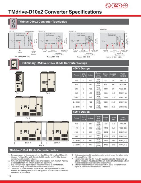
TMdrive-D<strong>10e2</strong> Converter SpecificationsTMdrive-D<strong>10e2</strong> Converter Topologies460/690 V ac460 V acCharging Resistor460/690 V ac460/690 V acSingle Phase ofPower ModuleSingle Phase ofPower ModuleSingle Phase ofPower ModuleSingle Phase ofPower ModuleGFDC Bus620 V dcGFDC Bus620/930 V dcGFDC Bus620/930 V dcGFDC Bus620/930 V dcACReactorGroundFaultDectectorChargingCircuit220 VacGround FaultCharging Circuit DectectorOptional DCCapacitor and FuseChargingCircuit220 VacGround FaultCharging Circuit DectectorOptional DCCapacitor and FuseChargingCircuit220 VacCharging CircuitGround FaultDectectorOptional DCCapacitor and Fuse150 Frame (460 V only) Frames 600 - 1400 Frames 1800 - 2800 Frames 2x1800 - 2x2800Preliminary TMdrive-D<strong>10e2</strong> Diode Converter Ratings460 V DesignFig. 1Fig. 2FrameCurrentEncl.Fig. # Voltage A dc(A ac)150 1 460250(204)600 2 460966(788)1200 2 4601932(1577)1800 3 4602898(2365)2400 3 4603864(3153)PowerkWLosseskWWidthmm (in)155 0.8 800 (31)600 6.0 1600 (63)1200 9.0 1600 (63)1800 12.0 3000 (118)2400 15.0 3000 (118)2 x 1800 4 4605796(4730)3600 24.0 5400 (213)2 x 2400 4 4607728(6306)4800 30.0 5400 (213)690 V DesignFig. 3Bank AFig. 4Bank BFrameCurrentEncl.Fig. # Voltage A dc(A ac)700 2 690773(631)1400 2 6901546(1262)2100 3 6902319(1892)2800 3 6903092(2523)2 x 2100 4 6904638(3784)2 x 2800 4 6906184(5046)PowerkWLosseskWWidthmm (in)720 3.0 1600 (63)1440 6.0 1600 (63)2160 9.0 3000 (118)2880 12.0 3000 (118)4320 18.0 5400 (213)5760 24.0 5400 (213)TMdrive-D<strong>10e2</strong> Diode Converter Notes1. Enclosures shown on this page are not more than 2335mm (92 in) tall and 605mm (24in) deep. For Figure 4 the width shown in the table includes bank A & B but does notinclude any inverters inserted between.2. Converters larger than frame 150 require external reactance of 3% minimum. Normally,a dedicated transformer is sufficient to satisfy this requirement.3. Dual bank converters require separate transformer windings for each half bridge.4. The currents ratings shown allow 150% overloads for 60 seconds.5. The 460Vac 150 frame converters include an IGBT braking module rated for 400A.Resistors with the ratings appropriate for the application must be supplied and externallymounted to use this function.186. Enclosures shown on this page include option of circuit breaker, but without built-inACL (except Frame 150).7. For converters larger than 150 frame, DC capacitors internal to the converter areoptional. This option should be used if the sum of all inverters frames sizes withoutDC disconnects connected to converter is less than 500.8. TMdrive-D<strong>10e2</strong> converters are not available with UL labels. <strong>Application</strong>s whichrequire UL labeled converters should use TMdrive-D10.