RTM 270/B - Berco S.p.A
RTM 270/B - Berco S.p.A
RTM 270/B - Berco S.p.A
- No tags were found...

Create successful ePaper yourself
Turn your PDF publications into a flip-book with our unique Google optimized e-Paper software.
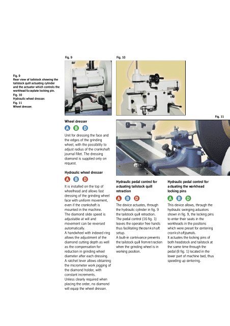
Fig. 9 Fig. 10Fig. 9Rear view of tailstock showing thetailstock quill actuating cylinderand the actuator which controls theworkhead fa ceplate locking pin.Fig. 10H yd raulic wheel dre s s e r.Fig. 11Wheel dre s s e r.Wheel dresserA B DUnit for dressing the face andthe edges of the grindingwheel, with the possibility toadjust radius of the crankshaftjournal fillet. The dressingdiamond is supplied only onrequest.Hydraulic wheel dresserA B DIt is installed on the top ofwheelhead and allows fastdressing of the grinding wheelface with uniform movement,even if the crankshaft ismounted in the machine.The diamond slide speed isadjustable at will andmovement can be reversedautomatically.A handwheel with indexed ringallows the adjustment of thediamond cutting depth as wellas the compensation forreduction in grinding wheeldiameter after each dressing.A ratchet lever allows obtainingthe micrometer work jogging ofthe diamond holder, withconstant increments.Unless clearly required whenplacing the order, no diamondwill equip the wheel dresser.H yd raulic pedal control fo ra ctuating tailstock quillre t ra ct i o nThe device actuates, thro u g hthe hyd raulic cylinder in fig. 9the tailstock quill re t ra ct i o n .The pedal control (16 fig. 1)l e aves the operator free handsthus facilitating the cra n k s h a ftsetup.A built-in contriva n ce pre ve n t sthe tailstock quill from re t ra ct i o nwhen the grinding wheel is inworking position.H yd raulic pedal control fo ra ctuating the wo r k h e a dlocking pinsA B D A B DThis device allows, through theh yd raulic swinging act u a t o rss h own in fig. 9, the locking pinsto enter their seats in theworkheads in the positionswhich we re preset for ce n t e r i n gc ra n k s h a ft journals.It actuates the locking pins ofboth headstock and tailstock atthe same time through thepedal (8 fig. 1) located in thel ower part of machine bed, thusspeeding up ce n t e r i n g .Fig. 11