Download Manual for Aero-naut Buecker Jungmeister 133
Download Manual for Aero-naut Buecker Jungmeister 133
Download Manual for Aero-naut Buecker Jungmeister 133
- No tags were found...

Create successful ePaper yourself
Turn your PDF publications into a flip-book with our unique Google optimized e-Paper software.
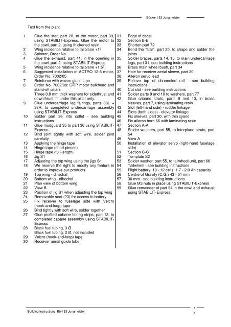
Bücker <strong>133</strong> <strong>Jungmeister</strong>Text from the plan:1 Glue the star, part 20, to the motor, part 39,using STABILIT-Express. Glue the motor tothe cowl, part 2, using thickened resin2 Wing incidence relative to tailplane +1º3 Spinner, Order No.4 Glue the exhaust, part 41, in the opening inthe cowl, part 2, using STABILIT-Express5 Wing incidence relative to tailplane +1.5º6 Suggested installation of ACTRO 12-5 motor,Order No. 7002/057 Rein<strong>for</strong>ce with woven glass tape8 Order No. 7002/88: GRP motor bulkhead andstand-off pillarsThree 0.8 mm thick washers <strong>for</strong> sidethrust anddownthrust; fit under this pillar only.9 Glue undercarriage leg fairings, parts 38L +38R, to completed undercarriage assemblyusing STABILIT-Express10 Solder part 36 into collet - see buildinginstructions11 Glue mudguard 35 to part 36 using STABILIT-Express12 Bind joint tightly with soft wire, solder jointcarefully13 Applying the hinge tape14 Hinge tape (short pieces)15 Hinge tape (full-length)16 Jig S117 Adjusting the top wing using the jigs S118 We reserve the right to modify any feature inorder to improve our products19 Top wing - dihedral20 Bottom wing - dihedral21 Plan view of bottom wing22 View B23 Position of jig S1 when adjusting the top wing24 Removable seat (23) <strong>for</strong> access to battery25 Fix receiver to fuselage side with Velcro(hook-and-loop) tape26 Bind tightly with soft wire, solder together27 Glue profiled cabane fairing strips, part 13, tocompleted cabane assembly using STABILIT-Express28 Black fuel tubing, 3 ØBlack fuel tubing, 2 Ø, not included29 Velcro (hook-and-loop) tape30 Receiver aerial guide tube31 Edge of decal32 Section B-B33 Shorten part 7234 Bend the “star”, part 20, to shape and solder thejoints35 Solder braces, parts 14, 15, to main undercarriagelegs, part 31; see building instructions36 Brass main wheel bush, part 3437 Hole <strong>for</strong> receiver aerial sleeve, part 3038 Aileron servo lead39 Relieve top of channeled rail - see buildinginstructions40 Cut slot - see building instructions41 Solder parts 9 and 10 to washers, part 7742 Glue cabane struts, parts 9 and 10, in brasssleeves, part 7, using laminating resin43 Slot (left-hand side) - rudder linkage44 Slots (both sides) - elevator linkage45 Fix sleeves, part 30, with thin cyano46 Fix aileron horn 56 with laminating resin47 Section A-A48 Solder washers, part 55, to interplane struts, part5449 View A50 Installation of elevator servo (right-hand fuselageside)51 Section C-C52 Template S253 Solder washer, part 55, to tailwheel unit, part 6654 Tailwheel - see building instructions55 Flight battery: 10 - 12 cells, 1.7 - 2.0 Ah capacity56 Centre of Gravity (C.G.) 43 - 51 mm57 30 mm - see building instructions58 Glue M3 nuts in place using STABILIT-Express59 Glue remainder of part 54 in the cowl and exhaustusing STABILIT-ExpressBuilding Instructions Bü-<strong>133</strong> <strong>Jungmeister</strong>11