Bücker <strong>133</strong> <strong>Jungmeister</strong>Adjusting the top wing:The kit includes two die-cut jigs S1. Carefully cut out these parts and the triangular gussets using abalsa knife. It is important that the jigs should be flat; if they are not, glue scrap pieces of spruce stripto them to stiffen them.Position the jigs S1 on the building board as shown on the plan. We recommend that you glue them inplace temporarily with cyano, using the gussets to set them exactly at right-angles to the buildingboard. Glue a scrap piece of 5 mm thick balsa or similar material centrally between them as shown -this <strong>for</strong>ms the support <strong>for</strong> the bottom wing.Place the model between the jigs, with the wing fitted inside them, and the wing trailing edges restingagainst the jigs S1. Pin the parts together. Check that the bottom wing rests squarely on the 5 mmsupport under the fuselage!Sand the joint areas of the cabane struts (9), (10) and (11) with abrasive paper prior to soldering. Takecare! Parts (9) and (10) are supplied in the kit as handed pairs, i.e. one left, one right: see fuselageplan view. This means that you must select the correct part (11) <strong>for</strong> each side of the cabane assembly,as the angled ends of parts (11) are not identical. Locate the end with the tighter bend, and bind ittightly to the rear cabane strut (10) using soft wire. Solder the joints carefully, noting that part (11)must be at right-angles to the angled bottom end of part (10) when viewed from above or below.Cut down the wing retainer screws (61) to a length of about 10 mm, and screw the cabane struts (9)and (10+11) to the right wing panel as shown on the plan (note position of screw loops). Now fit parts(9) and (10+11) in the brass tubes (7) which are already installed in the fuselage, align the top wingwith the jigs S1, and pin it in place with the trailing edge resting against the jigs. The left-hand parts (9)and (10+11) can now be fitted. Adjust the cabane struts (11) if necessary, bind the joints tightly withsoft wire, and solder them securely. The top wing should now be set at an angle of incidence of -0.5ºto -1.0º relative to the building board (= underside of bottom wing). If corrections are required at a laterstage, this can be done by placing packing washers on the cabane screw loops. Be<strong>for</strong>e gluing thecabane assembly permanently to the fuselage, attach the strut fairings (13) to the wire parts, cover thesurfaces with tissue and apply sanding sealer. Remove the top wing, file notches in those parts of thecabane which project into the fuselage, then roughen and de-grease the parts, including the inside ofthe brass tubes. Glue the cabane to parts (7) using laminating resin; fit the top wing, fix the model inthe jigs S1 as be<strong>for</strong>e, and leave it there until the resin has cured.The wing struts (54) consist of steel rods with an M2 thread at both ends. The length of the straightsection, i.e. between the top and bottom angles, is best found by taking direct measurements while themodel is still set up in the jigs S1. Fit two washers (55) on each wire strut and insert the struts in thewings. Position the washers resting against the wing surface and solder them to the wires, afterprotecting the wood with scrap paper or similar. Secure the bottom end of the struts with the washers(55) and M2 self-locking nuts (86). We recommend that you glue at least one half of the strut fairings(13) to the struts with cyano at this point.Mark the struts be<strong>for</strong>e removing them, to avoid mixing themup later.Undo and remove the top wing from the cabane, roughen the outside of the threaded sleeves (30.1),and screw them on the top end of the struts as far as the soldered-on washers. Run a little laminatingresin into the 3 mm Ø holes in the top wing and fit the model in the jigs S1 again. Place the top wingon the threaded sleeves, and screw the wing to the cabane assembly.Temporarily attach the ailerons to the wings. Assemble the link pushrods <strong>for</strong> the top ailerons usingparts (57-60), as shown in Section A-A.The top wing is removed as follows: first undo the four M2 nuts; of course, the top end of the struts isnow screwed to the wing. Unscrew the struts, glue the second half of the fairings to them, and sandthem to the correct profile. We recommend that you tissue-cover the strut fairings and seal thesurfaces.Place the undercarriage legs (31) and (32) in the fuselage channels as shown on the plan, and fit thestraps (17) to secure them. Attach the undercarriage cross-piece (15) to the legs, bind the joints tightlywith soft wire, and solder the joints. It is important that the wheels should have around 2º toe-in perside, as this improves the straight-running characteristics of the model considerably. Place thefuselage on the building board without the wheels, and hold a straight edge (steel rod or similar)against the front of the wheel axles. The outside end of the axles should touch the straight edge, and<strong>for</strong>m a curved gap towards the fuselage centreline. If necessary, adjust the angle of the axles until thisis the case. Remove the undercarriage and solder the top brace (14) to the assembly as shown on theplan. Carefully trim the undercarriage fairings (38) to fit and glue them to the legs using Stabilit-Express. Any gaps can be made good using polyester filler paste. The wheels (33) are designed <strong>for</strong> 4mm Ø axles, so <strong>for</strong> this model a 4/3 mm Ø brass reducer sleeve (34) must be pushed into each wheel.Building Instructions Bü-<strong>133</strong> <strong>Jungmeister</strong>6
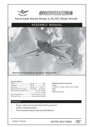
Bücker <strong>133</strong> <strong>Jungmeister</strong>Check that the wheels are absolutely free to spin, with very little axial play. A drop of thin oil willlubricate the wheels effectively.Roughen up the top section of the tailskid (66), file notches in it, and de-grease the surface. Solder thetop washer (55) in place be<strong>for</strong>e gluing the unit in the hole in the fuselage (using laminating resin).Open up the hole in the tailwheel (64) to 3 mm Ø, and press the 3/2 mm Ø brass sleeve (65) into it.Secure the wheel by soldering two washers (55) to the axle.The basic structure of the tail panels is completed at the factory. All you need to do is round off the tipsand sand the surfaces smooth. Drill 3 mm Ø holes <strong>for</strong> the horns (72) in the elevators and rudder, andapply thin cyano to the holes to strengthen the material.With the bottom wing attached to the fuselage, slide the tailplane into its slot. Check alignment with thewing, and measure the tail incidence and longitudinal dihedral. When you are confident that everythingis positioned correctly, glue the tailplane to the fuselage using laminating resin. Glue the fuselage tailpost (3) in place, followed by the fin.The motor cowl is attached to the fuselage as shown on the plan. Tip: tack a piece of plywood to themotor bulkhead on the motor cowl axis and mark the centrepoint. From this starting point it is easy tomeasure off the correct distance to the end of the three cowl support rails (8); this ensures that thecowl is truly central.The kit includes a number of optional scale fittings, and the plan clearly shows how these parts areinstalled. Just one tip here: the wire bars (36) which support the mudguards should be soldered intothe collets (37). Drill the collets to accept the wires using a 1.2 mm Ø bit.Preparing and covering the flying surfaces:Be<strong>for</strong>e covering we recommend that you give all the wooden parts a coat or two of thinned sandingsealer. When the sealer has set hard, rub down to a completely smooth surface using 400-gritabrasive paper, and blow away the sanding dust with compressed air. You have already sanded theGRP parts and ABS plastic mouldings, and they should now be de-greased using a detergent solution,and then allowed to dry really thoroughly be<strong>for</strong>e painting.The lightest covering material is probably iron-on film. However, as some parts of the model have tobe painted, you should ensure that the colours of the film and paint are a good match. We recommendOracover film and Orapaint colour paint, both in the colour CUB YELLOW. The paint adheres welleven on the film, i.e. you can safely spray the red areas onto the yellow Oracover. The dummy engine,exhaust pipe and instrument panel are best painted using enamels intended <strong>for</strong> plastic kits (e.g.Humbrol, Revell etc.).When the final finish has been applied, assemble the model completely, ready to fly, and balance it byadjusting the position of the flight battery (stated CG position refers to bottom wing). Fix the batterysecurely in its final position. You may find it necessary to use two packs, one above the other, in orderto balance the model correctly.Centre of Gravity 43-51Re-check the longitudinal dihedral, program the correct control surface travels and check that theundercarriage produces a straight ground-roll (check toe-in if not).As the model is relatively small and the power relatively high, the very large propeller produces quite amarked tendency to swing left on the take-off run. The best way of avoiding this problem is to increasemotor power gradually, initially accelerating with the tailwheel on the ground (i.e. with up-elevator heldin). Apply right rudder to maintain the correct heading, and when adequate speed has built up, returnthe elevator to neutral and continue to accelerate until the model lifts off by itself. The Bücker’shandling is extremely good-natured in the air. It is also capable of aerobatic manoeuvres, but its scopeBuilding Instructions Bü-<strong>133</strong> <strong>Jungmeister</strong>7