web / keypad configuration reader connection door contact ...
web / keypad configuration reader connection door contact ...
web / keypad configuration reader connection door contact ...
- No tags were found...

Create successful ePaper yourself
Turn your PDF publications into a flip-book with our unique Google optimized e-Paper software.
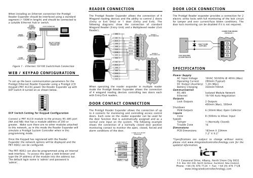
When installing an Ethernet <strong>connection</strong> the ProtégéReader Expander should be interfaced using a standardsegment (
AC POWER SUPPLYConnect the primary of a 16.5VAC, 50/60Hz, 40VATransformer to the electrical circuit and run the secondaryto the AC input on the controller terminals.The EOL (End Of Line) jumper setting MUSTbe set in the ON position for the FIRST andLAST module on the RS485 network. EOL isON when the jumper is closest to the EOLtext.2 Reader ExpanderQuick Start GuideINTRODUCTIONPRT-RDE2The Protégé Reader Expander extends the number ofcard <strong>reader</strong> inputs on the system by 2, number of zoneinputs by 8 (4 zones used for <strong>door</strong> monitoring andcontrol and up to eight can be used for extendedfunctionality) and the number of PGM outputs by 8(includes 2 monitored lock control outputs).• 4 Wiegand Reader Mode for 2 Entry/Exit Doors PerReader Expander• Secure Encrypted RS-485 Module Communications• Onboard Ethernet 10/100M Interface• 8 Zone Inputs• 2 Monitored Lock Control PGM Outputs• 6 Open Collector PGM Outputs (Reader ControlOutputs)• Intelligent Battery Charge and Monitoring• Smart Reader Missing/Tamper Monitoring• Online and Remote upgradeable firmwareFor a full installation manual or more information on theProtégé Reader Expander and other Integrated ControlTechnology products please login to our <strong>web</strong>sitewww.integratedcontroltechnology.comENCRYPTED MODULE NETWORKThe Protégé Reader Expander incorporates encrypted RS-485 communications technology. The isolatedcommunications interface offers full galvanic isolation toprevent ground loop noise and cross phase grounddifferential between network devices.Connection of the communications should be performedaccording to the diagram shown above. It is important thatthe N+ Network Communications Power be supplied froman independent battery backed power supply unit or anetworked module capable of supplying the required powerto all devices on the RS485 network.Always connect the Reader Expanders NA and NB terminalsto the NA and NB terminals of the communication network.The N+ and N- must go to a 12V power supply source asshown in the following diagram and connected at ONLY one+12V power source.CONFIGURATION SWITCHThe addressing of the Protégé Reader Expander allows upto 128 devices to be connected to the Protégé SystemController. The 'CONFIG' <strong>configuration</strong> DIP switch allowseach <strong>reader</strong> expander to have a unique address.The switch positions 1 to 7 select the device address from1 to 128. When setting an address the <strong>reader</strong> expandermust be powered down (Battery and AC) and restartedfor the new address to take affect. When changing theaddress the <strong>reader</strong> expander will automatically default theinternal <strong>configuration</strong> and require a network update. Seethe Protégé System reference manual for information onperforming a module update.The device address is determined by adding the value ofeach switch that is selected in the ON position and thenadding 1 to this value. In the example below the address079 results in (64+8+4+2) + 1 = 079. Setting alladdress switches to OFF results in the default address of001.ETHERNET NETWORK INTERFACEThe default Network settings are:PRT-RDE2 IP address 192.168.1.3Subnet Mask of 255.255.255.0Controller IP address 192.168.1.2