Protégé® Eclipse LED Keypad Installation Manual
Protégé® Eclipse LED Keypad Installation Manual
Protégé® Eclipse LED Keypad Installation Manual
- No tags were found...

Create successful ePaper yourself
Turn your PDF publications into a flip-book with our unique Google optimized e-Paper software.
<strong>Protégé®</strong> <strong>Eclipse</strong> <strong>LED</strong> <strong>Keypad</strong><strong>Installation</strong> <strong>Manual</strong>PRT-KLES
The specifications and descriptions of products and services contained in this manual were correct at the time of printing. Integrated Control Technology Limitedreserves the right to change specifications or withdraw products without notice. No part of this document may be reproduced, photocopied, or transmitted in anyform or by any means (electronic or mechanical), for any purpose, without the express written permission of Integrated Control Technology Limited. Designed andmanufactured by Integrated Control Technology Limited. <strong>Protégé®</strong> and the <strong>Protégé®</strong> Logo are registered trademarks of Integrated Control Technology Limited. Allother brand or product names are trademarks or registered trademarks of their respective holders.© Copyright Integrated Control Technology Limited 2003-2010. All rights reserved.
Table of Contents1.0 Welcome.............................................................................................................................22.0 <strong>Protégé®</strong> System Products...................................................................................................32.1 <strong>Protégé®</strong> System Management Suite................................................................................... 32.2 <strong>Protégé®</strong> Modules................................................................................................................ 33.0 Mounting............................................................................................................................44.0 Wiring and Configuration....................................................................................................54.1 Wire Loom........................................................................................................................... 54.2 Communication Connection................................................................................................. 64.3 Zone Input Wiring................................................................................................................ 74.4 Fire Zone Input Wiring......................................................................................................... 95.0 Programmable Output......................................................................................................106.0 Indicator Lights..................................................................................................................116.1 Arm/Armed Indicator......................................................................................................... 116.2 Disarmed Indicator............................................................................................................ 126.3 Power/Trouble Indicator.................................................................................................... 126.4 Message Indicator............................................................................................................. 126.5 Memory Indicator.............................................................................................................. 126.6 Error Code Indicator........................................................................................................... 126.7 Zone Display and Error Codes............................................................................................ 137.0 Audible Tones....................................................................................................................147.1 Configuration Tone............................................................................................................ 147.2 Rejection Tone.................................................................................................................... 148.0 <strong>Keypad</strong> Operation.............................................................................................................158.1 Second Function................................................................................................................. 159.0 Device Configuration.........................................................................................................169.1 Entering Device Configuration Mode................................................................................. 169.2 Address Selection (Menu 1)............................................................................................... 169.3 Device Options (Menu 2)................................................................................................... 179.4 Backlight Level (Menu 3).................................................................................................... 189.5 Firmware Version (Menu 4)............................................................................................... 199.6 Device Default (Menu 5).................................................................................................... 199.7 Exiting Device Configuration Mode.................................................................................... 1910.0 PRT-KLES Software Setup...................................................................................................2010.1 Auto Configuration.......................................................................................................... 2011.0 <strong>Keypad</strong> Setup....................................................................................................................2211.1 Auto Configuration.......................................................................................................... 2211.2 Options 1 Tab................................................................................................................... 2311.2.1 Display Options............................................................................................................. 2311.2.2 Access Options.............................................................................................................. 23
11.3 Options 2 Tab........................................................................................................................ 2411.3.1 Offline Options................................................................................................................... 2411.3.2 General Options................................................................................................................. 2411.3.3 Input Options..................................................................................................................... 2511.4 Access Level PGM................................................................................................................. 2512.0 Area Setup........................................................................................................................2612.1 Area PGMs....................................................................................................................... 2612.2 Exit Delay PGM................................................................................................................ 2712.3 Multiple <strong>Keypad</strong>s............................................................................................................. 2713.0 User Setup........................................................................................................................2813.1 Logging In........................................................................................................................ 2813.2 Disarming........................................................................................................................ 2813.3 Arming............................................................................................................................. 2814.0 Quick Reference................................................................................................................2914.1 Configuration Menu......................................................................................................... 2915.0 Mechanical Diagram..........................................................................................................3016.0 Technical Diagram.............................................................................................................3117.0 Technical Specifications.....................................................................................................3218.0 Ordering Information........................................................................................................3319.0 Warranty...........................................................................................................................34
1.0 Welcome!Thank you for purchasing the <strong>Protégé®</strong> <strong>Eclipse</strong> <strong>LED</strong> <strong>Keypad</strong> by Integrated Control Technology. The<strong>Protégé®</strong> System is an advanced technology security system specifically designed to enhance thefunctionality of security, building automation and access control by providing a completeintegrated solution with flexible local monitoring and offsite communication.The current features of the <strong>Protégé®</strong> <strong>Eclipse</strong> <strong>LED</strong> <strong>Keypad</strong> include:• 4x Onboard Zones• 1x Open Collector PGM Output• 1x Beeper• 2x PGM Controlled <strong>LED</strong>s• Capacitive Touch <strong>Keypad</strong>• Tamper SwitchWhen receiving the <strong>Protégé®</strong> <strong>Eclipse</strong> <strong>LED</strong> <strong>Keypad</strong> you should find the kit contains the items listedbelow. The kit type is clearly labelled on the packaging and will tell you what your kit contains.Please note that if you do not have the correct contents contact your distributor immediately.• <strong>Protégé®</strong> <strong>Eclipse</strong> <strong>LED</strong> <strong>Keypad</strong>• <strong>Protégé®</strong> <strong>Eclipse</strong> <strong>LED</strong> <strong>Keypad</strong> User <strong>Manual</strong>• 10 Way Wiring Loom• 8x 1k Resistors! Indicates a warning or advisory message relating to the section or location.? Indicates a hint or suggestion that relates to the section or location.[TEXT]ItalicsBold text enclosed in brackets is used to show a section number or address ofa programmable option or information on programming shortcut sequences.Italic text shows a reference to a example, section, page, manual or website.2
2.0 <strong>Protégé®</strong> System Products2.1 <strong>Protégé®</strong> System Management SuiteThe <strong>Protégé®</strong> System Management Suite application is a Windows® Vista (Business/Ultimate),Windows® 7, XP Professional and Server 2003 compatible Integrated Access Control and AlarmManagement System designed for any configuration from single site, single <strong>Protégé®</strong> IntegratedSystem Controller applications up to the global multi-national corporations using multiple site,multiple <strong>Protégé®</strong> Integrated System Controller installations.Product CodePRT-SMGT-ENTPRT-SMGT-PROPRT-SMGT-STNPRT-SMGT-1UDescription<strong>Protégé®</strong> System Management Suite Enterprise Edition<strong>Protégé®</strong> System Management Suite Professional Edition<strong>Protégé®</strong> System Management Suite Standard Edition<strong>Protégé®</strong> System Management Suite Single Client License Edition2.2 <strong>Protégé®</strong> ModulesThe <strong>Protégé®</strong> System can be expanded to accommodate large numbers of modules using theencrypted RS-485 Network. Modules that are currently available are listed below. Visitwww.incontrol.co.nz for the latest <strong>Protégé®</strong> Module and product information.Product CodePRT-CTRL-SEPRT-CTRL-LEPRT-TLCDPRT-ATH1PRT-KLCDPRT-ZX16-PCBPRT-ZXS16-PCBPRT-PX16-PCBPRT-PXS16-PCBPRT-RDM2-PCBPRT-RDS2-PCBPRT-RDI2-PCBPRT-RDE2-PCBPRT-ADC4-PCBPRT-DAC4-PCBPRT-COMMPRT-PX16-DRIPRT-PSU-5IPRT-HIODescription<strong>Protégé®</strong> SE Integrated System Controller<strong>Protégé®</strong> LE Integrated System Controller<strong>Protégé®</strong> Touchscreen <strong>Keypad</strong><strong>Protégé®</strong> Temperature and Humidity Sensor<strong>Protégé®</strong> Alphanumeric LCD <strong>Keypad</strong><strong>Protégé®</strong> 16 Zone Input Expander<strong>Protégé®</strong> Standard 16 Zone Input Expander<strong>Protégé®</strong> 16 PGM Output Expander<strong>Protégé®</strong> Standard 16 PGM Output Expander<strong>Protégé®</strong> Mini 2 Reader Expander<strong>Protégé®</strong> Standard 2 Reader Expander<strong>Protégé®</strong> Intelligent 2 Reader Expander<strong>Protégé®</strong> Ethernet 2 Reader Expander<strong>Protégé®</strong> Analog Input Expander<strong>Protégé®</strong> Analog Output Expander<strong>Protégé®</strong> RS-232 Serial Communication Interface<strong>Protégé®</strong> 16 Input Destination Reporting Interface<strong>Protégé®</strong> Intelligent 5 Amp Power Supply<strong>Protégé®</strong> Hi-O Network Door Control Module3
3.0 MountingThe <strong>Protégé®</strong> <strong>Eclipse</strong> <strong>LED</strong> <strong>Keypad</strong> in concert with the Protege Management Suite maintainscomplete control of your residence. It is intended to be mounted on a wall in a convenient placefor daily use.Step 1Select where to mount the <strong>Protégé®</strong> <strong>Eclipse</strong> <strong>LED</strong> <strong>Keypad</strong>.Step 2Remove the rear half of the <strong>Protégé®</strong> <strong>Eclipse</strong> <strong>LED</strong> <strong>Keypad</strong> by depressing the retaining clip androtating the case halves apart.Step 3Hold the rear case half against the wall and mark the mounting holes and cable entry area. Thecable entry area should align with a hole cut through the plaster wall-board. Cables are intended tobe run inside the wall. Use appropriate screws (not supplied) to affix the case to the wall.Step 4Run the wiring. Refer to later sections of this manual for the electrical connections. Leave about20cm (8”) of wire protruding through the center of the mounted half of the case.Step 5Connect the wiring to the <strong>Protégé®</strong> <strong>Eclipse</strong> <strong>LED</strong> <strong>Keypad</strong> electronics, then, to clip the case together,hook the top edges together then rotate and press the bottom in until you hear the clip snap intoplace.4
4.0 Wiring and ConfigurationThe wiring structure of the <strong>Protégé®</strong> <strong>Eclipse</strong> <strong>LED</strong> <strong>Keypad</strong> uses an encrypted RS-485 communicationinterface. Connections should be made in a daisy chain configuration, avoiding star and stubconnections.Encrypted RS-485 Module Network Encrypted RS-485 Module NetworkPRT-KLES - <strong>Protégé®</strong> <strong>Eclipse</strong> <strong>LED</strong> <strong>Keypad</strong>sFigure 1 - <strong>Eclipse</strong> <strong>LED</strong> <strong>Keypad</strong> Communication4.1 Wire LoomThe <strong>Protégé®</strong> <strong>Eclipse</strong> <strong>LED</strong> <strong>Keypad</strong>s are supplied with a wire loom attachment and are connectedusing a keyed 10 position snap lock connector. The 10 way wiring loom connection uses thefollowing color coding.REDBLACKBLUEWHITEORANGE(+12V)(0V)NANBZONE 1 (1+2)Network ConneconsPURPLEBROWNGREENYELLOWGRAYZONE 2 (3+4)PGM 1ZONE 3ZONE 40VZone Inputs andPGM OutputsFigure 2 - Wiring Loom Color Coding and Function5
4.2 Communication ConnectionSupport for up to 250 keypads per Controller is provided. Connection to the system controlleruses the network communication RS-485 interface. The <strong>Protégé®</strong> <strong>Eclipse</strong> <strong>LED</strong> <strong>Keypad</strong> also requirespower to be supplied to the N+ and N- terminals.+-+AUX-External +12V power supply. Ifmore than one power supply isused ensure that the 0V (-) isconnected to all other powersupply devices poweringmodules on the same systemcontroller.KEYPAD #1REDBLACKBLUEWHITE+12V0VNANBN+ N- NA NBN+ N- NA NBSystem Controller networkcommunicaon terminals andmodule network.RED+12VKEYPAD #2BLACKBLUE0VNAWHITENBRED+12VKEYPAD #250BLACKBLUEWHITE0VNANBFigure 3 - Communication Connection!When using more than one power supply to supply multiple wiring runs of<strong>Protégé®</strong> <strong>Eclipse</strong> <strong>LED</strong> <strong>Keypad</strong> connect the +12V terminals of only ONE powersupply unit to the N+ and N- terminals of the controller. Each power supply unitshould have the common (0V or -) connected together to ensure a common 0V.6
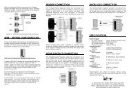
4.3 Zone Input WiringThe <strong>Protégé®</strong> <strong>Eclipse</strong> <strong>LED</strong> <strong>Keypad</strong> is capable of connecting to 4 zone inputs, each zone input canthen be programmed to perform the required function in the system.The following diagrams show each of the zone wiring configuration settings that are possible. Thezone configuration for the <strong>Protégé®</strong> <strong>Eclipse</strong> <strong>LED</strong> <strong>Keypad</strong> is programmed through the <strong>Protégé®</strong>System Management Suite software.!When using a tamper input on a device the tamper contacts must be normallyclosed and wired in series.!All resistors required to wire the zone configurations are provided with the<strong>Protégé®</strong> <strong>Eclipse</strong> <strong>LED</strong> <strong>Keypad</strong> in the accessory bag.Zone 1N.C. Zone ContactORANGEZone 1 (1+2)PURPLEZone 2 (3+4)BLACK0VZone 2N.C. Zone ContactFigure 4 - Zone Input (No Resistors)Zone 3N.C. Zone ContactGREENZone 3YELLOWZone 4GREY0VZone 4N.C. Zone ContactFigure 5 - Zone Input (No Resistors)7
Resistors should belocated at the deviceaached to the zoneZone 1N.C. Zone ContactORANGEZone 1 (1+2)1k1kN.C TamperPURPLEZone 2 (3+4)1k1kN.C TamperBLACK0VZone 2N.C. Zone ContactFigure 6 - Zone Input (1k and 1k)Resistors should belocated at the deviceaached to the zoneZone 3N.C. Zone ContactGREENZone 31k1kN.C TamperYELLOWZone 41k1kN.C TamperGREY0VZone 4N.C. Zone ContactFigure 7 - Zone Input (1k and 1k)Resistors should belocated at the deviceaached to the zoneZone 1N.C. Zone ContactZone 2N.C. Zone ContactORANGEZone 1 (1+2)1k2k4N.C TamperPURPLEZone 2 (3+4)1k2k4N.C TamperBLACK0VZone 3N.C. Zone ContactZone 4N.C. Zone ContactFigure 8 - Zone Input (1k and 2k4)!If Zones 1 & 2 are configured for duplex mode then they will become Zones 1, 2 ,3& 4 and will override the original Zones 3 & 4.8
4.4 Fire Zone Input WiringWhen wiring a zone to be a Fire Zone input the current programmed Zone Options will determinewhat resistors and configuration is required. Refer to the Zone Input Wiring section on page 7.Fire/Smoke Detecon UnitFire DeteconDevice PowerPOS+NEG-N.O. Fire ZoneContactFigure 9 - Fire/Smoke Detection Input!Fire Zones that are installed in Duplex mode operation are not recommended.Fire Zones should always be connected using the EOL resistor method (1k and 1k)as this provides both open and short circuit monitoring.?When a Fire Zone is connected to a zone input that is used in the Duplex Zoneconfiguration a Fire Zone fault will not be shown when the Fire Zone has a shortedcondition as this is shown as all zones closed. A Fire Loop Trouble will be shownwhen the zone is tampered.?The <strong>Protégé®</strong> <strong>Eclipse</strong> <strong>LED</strong> <strong>Keypad</strong> is designed to be used with non-latching smokedetectors. If latching smoke detectors are used then a separate PGM will berequired to reset them. This can be triggered by the smoke reset function of thekeypad.9
5.0 Programmable OutputThe <strong>Protégé®</strong> <strong>Eclipse</strong> <strong>LED</strong> <strong>Keypad</strong> contains a Programmable Output (PGM) that may be configuredto activate during an alarm condition. This Output can be programmed through the <strong>Protégé®</strong>System Management Suite software as described in section 12.0.PGM 1BROWN0VBLACKFigure 10 - Programmable Output+12VRED<strong>LED</strong>PGM 1BROWN1K5 OHMFigure 11 - <strong>LED</strong> Example!The PGM Output of the <strong>Protégé®</strong> <strong>Eclipse</strong> <strong>LED</strong> <strong>Keypad</strong> is designed for a maximumcurrent of 50mA. If using it to trigger an external siren then a relay must be used.10
6.0 Indicator LightsThe <strong>Protégé®</strong> <strong>Eclipse</strong> <strong>LED</strong> <strong>Keypad</strong> features six status indicator lights and ten zone/error codeindicator lights showing the condition of the <strong>Protégé®</strong> Security System.DisarmedArm/ArmedPower/TroubleAlarm MemoryZone/Error Code IndicatorsError Code IndicatorMessageFigure 12 - Indicator Lights6.1 Arm/Armed IndicatorStateOffOnOn with keypad emitting acontinuous toneFlashing regularlyDescriptionThe system is disarmed.The system is armed and you may enter your User code to disarm.The system is armed and has entered the Entry Delay state.You must enter your User code to disarm.The system is in Exit delay. You have a limited time to leave theArea before it becomes armed.11
6.2 Disarmed IndicatorStateOffOnDescriptionThe system is Armed.The system is Disarmed.6.3 Power/Trouble IndicatorStateOffOnFlashingPulsingDescriptionComplete power failure.The system is powered and operating normally.There is a trouble condition present.A User is logged in and may Arm or Disarm the system.6.4 Message IndicatorStateOffFlashingDescriptionNormal operation.The concierge is requesting your attention.6.5 Memory IndicatorState3OffFlashingDescriptionNormal operation.An alarm has been triggered and the Zones that caused the Alarm havebeen recorded in Alarm memory.6.6 Error Code IndicatorStateOffOnFlashing with allnumber <strong>LED</strong>s blankDescriptionNormal operation.The Area cannot be armed due to a specific reason. The Error codeis displayed as one of the Number <strong>LED</strong>s being lit. Refer to the sectionbelow for a list of error codes.The keypad has been locked due to too many incorrect login attempts.12
6.7 Zone Display and Error CodesThe <strong>Protégé®</strong> <strong>LED</strong> <strong>Keypad</strong> features an easy to use numeric display for indicating Zones or otherconditions which are stopping the system from arming. When attempting to arm the system, if aZone is open then the keypad will emit a long rejection beep then display the open Zone as aflashing number on the keypad.For Zones higher than Zone 9, the 0 will also be lit and represents the ‘tens’ digit. For example ifZone 15 is open then the 0 and the 5 will be flashing.If some other condition is stopping the system from arming then this is displayed as an Error Code.When displaying Error Codes the ‘ ’ will be lit and a number corresponding to the Code will beturned on. A list of the error codes is shown in the following table.Code Description1 Stay Arming is not allowed2 Force Arming is not allowed3 Instant Arming is not allowed4 Too many Zones have been bypassed5 Interlock active - Cannot arm because another Area is disarmed.6 User count not zero - The system has recorded that someone has entered the Area and has not left.13
7.0 Audible TonesWhen you press a key on the <strong>Protégé®</strong> <strong>Eclipse</strong> <strong>LED</strong> <strong>Keypad</strong> a short audible tone is generated. Othertones are generated when certain functions are used, you should be familiar with the followingaudible tone outputs.7.1 Confirmation ToneWhen an operation (e.g. Arming) is successfully entered on the keypad or when the systemswitches to a new status/mode, the keypad generates a series of four audible tones.7.2 Rejection ToneWhen the system times out or when an operation is incorrectly entered on the keypad, it willgenerate a continuous audible tone for one second.14
8.0 <strong>Keypad</strong> OperationThe <strong>Protégé®</strong> <strong>Eclipse</strong> <strong>LED</strong> <strong>Keypad</strong> features 15 keys. Four of these keys have a second functionassociated with them.Second Function KeyArm KeyUnlock Key1 Key (2nd Fn STAY Key)4 Key (2nd Fn BYPASS Key)3 Key (2nd Fn MEMORY Key)2 Key (2nd Fn FORCE Key)Clear KeyEnter KeyFigure 13 - <strong>Keypad</strong> OperationKeyARMFunctionWhen Regular Arming is enabled, the Arm key is used to arm the system.FNCThe Second Function key enables the second function of four of the number keys. Refer to thefollowing section for details.MENU To unlock key can be configured to unlock an associated door.0-9 NUMBER The number keys are used for entering User codes or configuring system settings.CLEAR The Clear key is used to cancel a partially typed User code, or partially entered system setting.ENTER Enter is used to confirm a entry when altering system settings.8.1 Second FunctionFour of the number keys have a second function assigned.Step 1To access the second function of these numbers press the SECOND FUNCTION key ( ). The fourkeys (1, 2, 3, and 4) will light up.Step 2Now press the desired key to select STAY, FORCE, MEMORY or BYPASS. Pressing any other key willcancel second function mode.15
9.0 Device Configuration9.1 Entering Device Configuration ModeBefore the <strong>Protégé®</strong> <strong>Eclipse</strong> <strong>LED</strong> <strong>Keypad</strong> module will communicate it must be assigned an addressand programmed with specific options as to how it will operate. This is achieved by accessing theDevice Configuration menu.!The Device Configuration menu can only be accessed in the first two seconds whenthe device powers up. It is not able to be accessed when the system is operational.Step 1To gain access to the Device Configuration menu, apply power to the device.Step 2Within the first two seconds after the four beep tone is heard, press the CLEAR key ( ), followedby the ENTER key ( ). Note: If any key is held down while the device is powered up the key willnot be registered.Step 3The ARM <strong>LED</strong> and READY <strong>LED</strong> will then begin flashing to notify that Device Configuration mode hasbeen entered. You can then press the key corresponding to the menu required (as detailed in thefollowing sections).9.2 Address Selection (Menu 1)The Address Selection sets the address of the <strong>Protégé®</strong> <strong>Eclipse</strong> <strong>LED</strong> <strong>Keypad</strong>, this address must be aunique address on the system from 1 to 250.To View the Current AddressStep 1To view the current address enter the following key press sequence:, 1,The address will be displayed as a sequence of three Number <strong>LED</strong>s lighting one after the othercorresponding to each of the three digits of the address.16
To Change the Current AddressStep 1To change the current address enter following key press sequence:, 1, [ADDRESS 1], [ADDRESS 2], [ADDRESS 3],The device will beep four times to indicate that it has changed the address.!All three digits must be entered when programming an address. This means thatfor addresses below 100, you must enter [0] then the 2 digits of the address.For addresses below 10, you must enter [0], [0] followed by the address digit.9.3 Device Options (Menu 2)The Device Options set options that relate to the mode of operation of the <strong>Protégé®</strong> <strong>Eclipse</strong> <strong>LED</strong><strong>Keypad</strong>.Step 1To enter the Device Options menu enter the following key press sequence:, 2The currently assigned Device Options will be displayed using the Number <strong>LED</strong>s.Step 2To toggle options press the keys 1 to 8 and the corresponding key <strong>LED</strong> will be lit when that optionis ENAB<strong>LED</strong>.The available options are:Option 1 - <strong>Keypad</strong> beep• Enabled, the <strong>Keypad</strong> will not make a sound when a key is pressed.• Disabled, the <strong>Keypad</strong> will beep when keys are pressed.Option 2 - Zone Duplex• Enabled, Zone inputs 1 & 2 can be wired in Duplex mode to create Zones 1,2,3 & 4. PhysicalZone inputs 3 & 4 have no effect.• Disabled, All physical Zones are treated as individual Zones.Option 3 - Beep on Communication Failure• Enabled, the <strong>Keypad</strong> will emit a periodic beep if communication with the <strong>Protégé®</strong> IntegratedSystem Controller fails.• Disabled, the <strong>Keypad</strong> will not emit a periodic beep if communication with the <strong>Protégé®</strong>Integrated System Controller fails.17
Option 4 - Clear key toggles keypad beep• Enabled, pressing and holding the CLEAR key ( ) for two seconds will toggle Option 1 on andoff.• Disabled, pressing and holding the CLEAR key ( ) for two seconds will have no effect.Option 5 to 7 - ReservedOption 8 - Arm <strong>LED</strong> follows beeper• Enabled, If the beeper is set to pulse on and off (as is the default setting for Exit Delay) thenthe ARM <strong>LED</strong> will flash at the same time. When the beeper is silent or continuously on theARM <strong>LED</strong> will operate independently.• Disabled, The ARM <strong>LED</strong> is controlled completely independently to the beeper.Step 3Pressing the ENTER key ( ) will save the options. Pressing the MENU key ( ) will abort theoperation without saving the options.9.4 Backlight Level (Menu 3)The brightness of the <strong>LED</strong>s when not active can be adjusted.To View the Current Backlight SettingStep 1To view the current Backlight setting enter the following key press sequence:, 3,The current Backlight setting will be displayed as a sequence of three number <strong>LED</strong>s lighting oneafter the other corresponding to each of the three digits of the setting.To Change the Current Backlight SettingStep 1To change the current backlight setting enter the following key press sequence:, 3, [SETTING 1], [SETTING 2], [SETTING 3],The device will beep four times to indicate that it has changed the Backlight setting. Note thatthe highest value that can be assigned is 015.!All three digits must be entered when programming a Backlight setting. This meansthat for a setting below 100, you must enter [0] then the 2 digits of the setting.For settings below 10, you must enter [0] , [0] followed by the setting digit.18
9.5 Firmware Version (Menu 4)The <strong>Protégé®</strong> <strong>Eclipse</strong> <strong>LED</strong> <strong>Keypad</strong> contains two microprocessors each with it’s own firmware.Step 1To view the version of firmware that is installed in the main microprocessor enter the following keypress sequence:, 4, 1,The main microprocessor firmware version will be displayed as a sequence of four number <strong>LED</strong>slighting one after the other. The first two digits are the major version number and the second twodigits are the minor version number.Step 2To view the version of firmware that is installed in the keypad microprocessor enter the followingkey press sequence:, 4, 2,The keypad microprocessor firmware version will be displayed as a sequence of four number <strong>LED</strong>slighting one after the other. The first two digits are the major version number and the second twodigits are the minor version number.9.6 Device Default (Menu 5)Step 1To Default all the Device Options enter the following key press sequence:, 5The ARMED <strong>LED</strong> will now flash more rapidly.Step 2Press the ENTER key ( ) to confirm or the MENU key ( ) to cancel.9.7 Exiting Device Configuration ModeStep 1Once Device Configuration is complete, press the CLEAR key ( ) to restart the keypad.!If you do not press any key for 45 seconds while in Device Configuration mode, thekeypad will automatically restart.19
10.0 PRT-KLES Software SetupThe <strong>Protégé®</strong> <strong>Eclipse</strong> <strong>LED</strong> <strong>Keypad</strong> connects to a <strong>Protégé®</strong> System Controller and registers as a<strong>Keypad</strong> in exactly the same way that other <strong>Protégé®</strong> <strong>Keypad</strong>s do. Unlike the PRT-KLCD andPRT-K<strong>LED</strong>, the <strong>Protégé®</strong> <strong>Eclipse</strong> <strong>LED</strong> <strong>Keypad</strong> (PRT-KLES) can only control a single Area.10.1 Auto ConfigurationWhen the <strong>Protégé®</strong> <strong>Eclipse</strong> <strong>LED</strong> <strong>Keypad</strong> registers on a System Controller for the first time, itconfigures various default settings. These settings are configured within the System Controllersinternal database. To ensure that the <strong>Protégé®</strong> System Management Suite Software does notoverwrite the default settings they must be uploaded to the Software before any modifications canbe made and downloaded. Failure to upload the default settings simply means that the Installerwill need to configure them manually. If the keypad goes off-line then re-registers at the sameaddress (for example, after a power cycle) then it will not alter any settings. It is only when it firstregisters that the default settings are applied.Every keypad has one associated Area. When the <strong>Protégé®</strong> <strong>Eclipse</strong> <strong>LED</strong> <strong>Keypad</strong> registers at aparticular address, the ‘Area this LCD belongs to’ will be the Area that corresponds to it’s addressi.e. <strong>Keypad</strong> 5 will be assigned Area 5.Figure 14 - Auto ConfigurationThat Area then has it’s Entry Delay, Exit Delay, Armed and Disarmed PGMs assigned to the relevantPGMs on the respective keypad.20
Figure 15 - Auto ConfigurationNote that the ‘Exit Delay PGM’ by default is assigned to only the beeper of the keypad, not thebeeper and ARM <strong>LED</strong>. When the <strong>Keypad</strong> is in Exit Delay it is desirable to flash the ARM <strong>LED</strong> as wellas sound the beeper. To achieve this an option can be selected within the internal setup of thekeypad (described in section 9.3) which causes the ARM <strong>LED</strong> to flash when the beeper is set topulse on and off. Alternately a PGM group could be set up with both the beeper and the ARM <strong>LED</strong>in it.21
11.0 <strong>Keypad</strong> SetupThe <strong>Protégé®</strong> <strong>Eclipse</strong> <strong>LED</strong> <strong>Keypad</strong> is conveniently auto-configured for the most common usage. Tomodify the set up use the <strong>Protégé®</strong> System Management Suite software as described in this andthe following sections.11.1 ConfigurationFigure 16 - ConfigurationPoll time for the LCDAre this LCD belongs toDual Code TimeoutLockout <strong>Keypad</strong> TimeDoor Number connected to<strong>Keypad</strong>Menu Group for this <strong>Keypad</strong>Area Group for this <strong>Keypad</strong>Defines the length of time between “are you still connected?” messages. If amodule fails to respond to one of these messages it will be put offline. Unlessthere is a specific requirement, leave this as the default setting of 250.This is the Area which the keypad controls. The PRT-KLES can only control a singleArea. By default the Area whose Index corresponds to the <strong>Keypad</strong>s address is set,but any valid Area can be set here.Not relevant to the PRT-KLES.If the ‘Lock <strong>Keypad</strong> on Excess attempts’ option is selected and a User enters threeinvalid user codes in a row, then this setting defines the length of time that thekeypad will be rendered inactive.If either the ‘Function Key Unlocks Door When Logged In’ or ‘Function Key UnlocksDoor When Logged Out’ option is selected, then this setting defines the Door thatwill be unlocked.Leave blank. If set, then the Users menu group and the <strong>Keypad</strong> menu group musthave at least one menu in common for the keypad to function (even thoughPRT-KLES doesn’t use menus).Leave blank. If set, then the Area group must contain the keypads primary area.Smoke reset PGM When the CLEAR ( ) key and ENTER ( ) key are held down together for twoseconds or more the keypad will send a Smoke Reset message to the SystemController. This setting defines which PGM to activate to reset the Smoke Alarms.Time User is Logged InDefined the length of time before a User will be automatically logged out if there isno <strong>Keypad</strong> activity.22
11.2 Options 1 TabFigure 17 - Options 1 Tab11.2.1 Display OptionsDisplay Primary Area StatusDisplay Scrollable Area GroupMust be set for the KLES to operate as expected.Must be left blank for the PRT-KLES to operate correctly.All other options are not relevant to the PRT-KLES.11.2.2 Access OptionsFunction Key Unlocks Door When LoggedIn (REN)Function Key Unlocks Door when LoggedOut (REX)Auto Logout After User ArmingLock keypad on excess attemptsWhen selected, the Unlock key ( ) will unlock the Door which wasspecified under the ‘Configuration’ tab when a User is logged in.When set, the Unlock key ( ) will unlock the Door which was specifiedunder the ‘Configuration’ tab when no User is logged in.If set then the User will be automatically logged out after they havearmed the Area assigned to this keypad. It is recommended that thisoption be selected for the <strong>Protégé®</strong> <strong>Eclipse</strong> <strong>LED</strong> <strong>Keypad</strong>.If set, will lock the keypad after 3 incorrect attempts at a PIN. The lockout time is specified in the Configuration tab. When locked the keypadwill be blank with the Clear key ( ) flashing.All other options are not relevant to the PRT-KLES.23
11.3 Options 2 TabFigure 18 - Options 2 Tab11.3.1 Offline Options<strong>Keypad</strong> login requires cardWhen enabled, the keypad will require access card verification alongwith a user code before the user login can succeed.All other options are not relevant to the PRT-KLES.11.3.2 General OptionsDisable the LCD <strong>Keypad</strong> BeeperDuplex Zones (4 keypad zones)Beep on Communication FailureClear key can disable Key press beeperVirtual ModuleIf selected, then the keypad will not beep when keys are pressed. Thebeeper will still sound during Entry and Exit delay and if an alarm istriggered.Not necessary with the <strong>Protégé®</strong> <strong>Eclipse</strong> <strong>LED</strong> <strong>Keypad</strong> as it has fourseparate Zone inputs. If selected then Zones 1 & 2 can be duplexed toform Zones 1-4.When set, the keypad will make a beep-beep sound every 90 secondsif it has lost communications with the System Controller.When enabled, pressing and holding the ‘ ’ key will toggle the keypress sound on and off.Defines the keypad as Virtual (for testing purposes). Do not select if aphysical <strong>Protégé®</strong> <strong>Eclipse</strong> <strong>LED</strong> <strong>Keypad</strong> exists.24
11.3.3 Input OptionsActivate Access Level PGM Only On ValidAccessAlways Activate Access Level PGMIf, under the Access Level set up for the User that is logging in, an‘Activation PGM’ has been set, then this PGM will be triggered whenthat User logs in.See the note Access Level PGM below.11.4 Access Level PGMThe <strong>Protégé®</strong> <strong>Eclipse</strong> <strong>LED</strong> <strong>Keypad</strong> does not use Menus so typically the Menu Group setting wouldbe left blank, and any User with access to the <strong>Keypad</strong>s Area is able to log into the keypad. It ishowever possible to configure the <strong>Keypad</strong> with a defined Menu Group in order to reject Userswho are not included in that Group.If this is done and the option ‘Always Activate Access Level PGM’ is selected, then a User witha valid login code but without access to any of the Menus in the <strong>Keypad</strong>s Menu Group will beblocked from logging in to the keypad but will activate the specified PGM.This feature may be used for a specific user (e.g. a Courier can unlock a locker by entering a code)or as a general function (e.g. entering code ‘1’ turns the lights on).25 6
12.0 Area SetupThe <strong>Protégé®</strong> <strong>Eclipse</strong> <strong>LED</strong> <strong>Keypad</strong> is designed to Arm and Disarm a single Area. It is not intended tobe used to control Area Groups or for different Users to access different Areas. The Area assignedto the <strong>Keypad</strong> can be any valid Area, however by default the Area whose Index corresponds to the<strong>Keypad</strong>s Address is assigned (e.g. Area #5 is assigned to <strong>Keypad</strong> #5).Only the Area set-up that is relevant to the <strong>Protégé®</strong> <strong>Eclipse</strong> <strong>LED</strong> <strong>Keypad</strong> is shown here. For furtherinformation on setting up an Area please refer to the <strong>Protégé®</strong> Integrated System ControllerReference <strong>Manual</strong>.12.1 Area PGMsIn order for the Arm <strong>LED</strong>, the Ready <strong>LED</strong> and the beeper to operate as expected they must be setup under the Area PGMs properties. These are set by default, but if the default Area is not usedwith the keypad then they must be set up manually.Figure 19 - Area PGMs26
Bell PGM OutputExit Delay PGM OutputEntry Delay PGM OutputThe PGM which activates the siren when an alarm goes off.See the note Exit Delay PGM below.The PGM which is activated during the Entry Delay. Typically acontinuous tone from the <strong>Keypad</strong>s beeper.Disarmed PGM OutputThe PGM which is activated when the Area is Disarmed. Typically KPxxxGreen <strong>LED</strong>.Armed PGM OutputThe PGM which is activated when the Area is Armed. Typically KPxxxRed <strong>LED</strong>.... Other settings as desired. Refer to the <strong>Protégé®</strong> Integrated SystemController Reference <strong>Manual</strong> for a full description of Area setup.12.2 Exit Delay PGMThe Exit Delay PGM (as with the other PGMs) can be set to any PGM or PGM Group on thesystem, however it is desirable for it to be configured so that the <strong>Keypad</strong> emits a pulsed beep-beepsound and the Arm <strong>LED</strong> flashes at the same rate during Exit Delay. To avoid the requirement ofsetting up a PGM group, the <strong>Keypad</strong> has a special feature which links the pulsing beeper to theArm <strong>LED</strong>.When the Exit Delay PGM is set to pulse the beeper, the Arm <strong>LED</strong> will automatically flash as well(refer to section 9.3 to disable this feature if not required). When the beeper is not set to pulse,the beeper PGM and the Arm <strong>LED</strong> PGM operate independently. Note that the ‘On time’ and ‘Offtime’ are programmed in multiples of 100 milliseconds.12.3 Multiple <strong>Keypad</strong>sIf more that one <strong>Protégé®</strong> <strong>Eclipse</strong> <strong>LED</strong> <strong>Keypad</strong> is used to control a single Area then the Installer willneed to set up PGM Groups which contain the relevant <strong>LED</strong>s & beepers for the <strong>Keypad</strong>s, andassign these Groups to the Area PGM settings.27
13.0 User SetupNo special User setup is required for a User to access a <strong>Protégé®</strong> <strong>Eclipse</strong> <strong>LED</strong> <strong>Keypad</strong>. For details ofthe normal User setup procedure please refer to the <strong>Protégé®</strong> Integrated System ControllerReference <strong>Manual</strong>.It is useful to note that although the <strong>Protégé®</strong> <strong>Eclipse</strong> <strong>LED</strong> <strong>Keypad</strong> does not have the menustructure of the other <strong>Protégé®</strong> <strong>Keypad</strong>s, it still uses the same programming and is equivalent to akeypad which only allows access to menu ‘1. Arm/Disarm’.13.1 Logging InThe User can type in their variable length code then press Enter to log in (as per the PRT-KLCD).When logged in the Power <strong>LED</strong> will pulsate (fade in and out) to indicate that the User is logged in.The User can press the CLEAR key ( ) to log out, or will be automatically logged out after the logintime defined in their set up has expired.Selecting the User setting “Go directly to the Menu on login (No Area Control)” under the Userproperties General Options has no effect when logging into a <strong>Protégé®</strong> <strong>Eclipse</strong> <strong>LED</strong> <strong>Keypad</strong>. Ineffect, the User is always directed to Area control.If a Users setup does not allow access to the Arm/Disarm menu then they will be logged outimmediately after they log in, and the Area state will not change.13.2 DisarmingWhen the Area is armed and the User is logged out, the User simply types in their PIN to disarmthe Area.The “Turn Off the Primary Area If User Has Access On Login” option in the User properties GeneralOptions is effectively always set for the <strong>Protégé®</strong> <strong>Eclipse</strong> <strong>LED</strong> <strong>Keypad</strong>.13.3 ArmingBy default the ‘Auto Logout After User Arming’ setting under the <strong>Keypad</strong> properties Option 1 isselected. As there is only one Area to arm this gives the most user friendly interface for the<strong>Keypad</strong>, although it can be deselected if desired.28
14.0 Quick Reference14.1 Configuration MenuTo enter the Configuration menu press the CLEAR key ( ), then press the ENTER key ( ) withintwo seconds after power up.Key SequenceDescription,1, View the current address,1, [A1], [A2], [A3], Set the current address,2, 1, Toggle ‘<strong>Keypad</strong> Beep’ Option 1 (Default: Enabled),2, 2, Toggle ‘Zone Duplex’ Option 2 (Default: Disabled),2, 3, Toggle ‘Beep on Communication Failure’ Option 3 (Default: Enabled),2, 4, Toggle ‘Clear Key Toggles <strong>Keypad</strong> Beep’ Option 4 (Default: Enabled),2, 8, Toggle ‘Arm <strong>LED</strong> Follows Beeper’ Option 8 (Default: Enabled),3, View the current backlight setting,3, [B1], [B2], [B3], Set the current backlight setting,4, 1, View the main processor firmware version,4, 2, View the keypad processor firmware version,5, Default the system29
15.0 Mechanical DiagramThe mechanical diagram shown below outlines the essential details needed to help ensure thecorrect installation of the <strong>Protégé®</strong> <strong>Eclipse</strong> <strong>LED</strong> <strong>Keypad</strong>.DisarmedArm/ArmedPower/TroubleAlarm MemoryZone/Error Code IndicatorsError Code IndicatorMessageMounting HolesTamper SwitchWiring Loom SocketCase Disassembly TabFigure 20 - Mechanical Diagram30
16.0 Technical DiagramThe technical diagram shown below outlines the essential details needed to help ensure thecorrect installation of the <strong>Protégé®</strong> <strong>Eclipse</strong> <strong>LED</strong> <strong>Keypad</strong>.54mm4.5mmdiameter40mm34.5mm16.5mm10mm97mm48mmPRT-KLES82.5mm100.5mm107mm117mm10.5mm17.5mm37.5mm57.5mm64.5mm75mmFigure 21 - Technical Diagram31
17.0 Technical SpecificationsThe following technical specifications are important and vital to the correct operation of the<strong>Protégé®</strong> <strong>Eclipse</strong> <strong>LED</strong> <strong>Keypad</strong>. Failure to adhere to the technical specifications will result in anywarranty or guarantee that was provided becoming NULL AND VOID.Integrated Control Technology continually strives to increase the performance of its products andas a result the specifications may change without notice. It is recommended that you alwaysconsult www.incontrol.co.nz for the latest documentation and product information.Operating VoltageOperating CurrentUser Interface Display/<strong>Keypad</strong>Zone Inputs (System Zones)Zone Inputs (Enclosure Tamper)PGM Outputs11.5VDC to 24VDC50mA (80mA max)Combined 15 key capacitive touch keypad with 10x zone status <strong>LED</strong>sand 6x system status <strong>LED</strong>s.4 using standard or duplexed mode.PCB mounted external micro switch assembly.1x open collector output for general functions (negative output, 50mAmax).Display and Audible FunctionsArmed, ready and beeperOperating Temperature5˚ to 55˚C (41˚ to 131˚F)Storage Temperature-10˚ to 85˚C (14˚ to 185˚F)Humidity0% to 85% (Non condensing)Dimensions (H x W x D) 118 x 75 x 19mm (4.65 x 2.95 x 0.9”)Weight148g (5.23oz)Specifications are subject to change without notice, please visit www.incontrol.co.nz for updated information.32
18.0 Ordering InformationPlease use the following product codes when placing an order for the <strong>Protégé®</strong> <strong>Eclipse</strong> <strong>LED</strong> <strong>Keypad</strong>.• PRT-KLES<strong>Manual</strong>s and literature are available at the Integrated Control Technology website in thedocumentation section. If you require manuals on CD-ROM please request a Resource CD-ROMfrom the website.33
19.0 WarrantyThe Seller warrants its products to be free from defects in materials and workmanship undernormal use for a period of one year. Except as specifically stated herein, all express or impliedwarranties whatsoever, statutory or otherwise, including without limitation, any implied warrantyof merchantability and fitness for a particular purpose, are expressly excluded. The Seller does notinstall or connect the products and because the products may be used in conjunction withproducts not manufactured by the Seller, the Seller cannot guarantee the performance of thesecurity system. Seller’s obligation and liability under this warranty is expressly limited torepairing or replacing, at Seller’s option, any product not meeting the specifications. In no eventshall the Seller be liable to the buyer or any other person for any loss or damages whether director indirect or consequential or incidental, including without limitation, any damages for lostprofits, stolen goods, or claims by any other party caused by defective goods or otherwise arisingfrom the improper, incorrect or otherwise faulty installation or use of the merchandise sold.<strong>Protégé®</strong> and the <strong>Protégé®</strong> Logo are registered trademarks of Integrated Control TechnologyLimited.34
This page has been intentionally left blank
This page has been intentionally left blank
Integrated Control Technology Limited11 Canaveral Drive, Albany, North Shore City 0632, Auckland, New ZealandP.O. Box 302-340, North Harbour, Auckland, New ZealandPhone: +64 (9) 476 7124Fax: +64 (9) 476 7128Email: support@incontrol.co.nzwww.incontrol.co.nzDesigners and manufacturers of integrated electronic access control, security and building automation products.Designed and manufactured by Integrated Control Technology Limited.© Copyright Integrated Control Technology Limited 2003-2010. All rights reserved.227-4190-021