Protégé® Eclipse LED Keypad Installation Manual
Protégé® Eclipse LED Keypad Installation Manual
Protégé® Eclipse LED Keypad Installation Manual
- No tags were found...

Create successful ePaper yourself
Turn your PDF publications into a flip-book with our unique Google optimized e-Paper software.
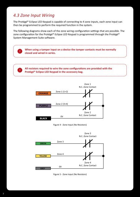
4.3 Zone Input WiringThe <strong>Protégé®</strong> <strong>Eclipse</strong> <strong>LED</strong> <strong>Keypad</strong> is capable of connecting to 4 zone inputs, each zone input canthen be programmed to perform the required function in the system.The following diagrams show each of the zone wiring configuration settings that are possible. Thezone configuration for the <strong>Protégé®</strong> <strong>Eclipse</strong> <strong>LED</strong> <strong>Keypad</strong> is programmed through the <strong>Protégé®</strong>System Management Suite software.!When using a tamper input on a device the tamper contacts must be normallyclosed and wired in series.!All resistors required to wire the zone configurations are provided with the<strong>Protégé®</strong> <strong>Eclipse</strong> <strong>LED</strong> <strong>Keypad</strong> in the accessory bag.Zone 1N.C. Zone ContactORANGEZone 1 (1+2)PURPLEZone 2 (3+4)BLACK0VZone 2N.C. Zone ContactFigure 4 - Zone Input (No Resistors)Zone 3N.C. Zone ContactGREENZone 3YELLOWZone 4GREY0VZone 4N.C. Zone ContactFigure 5 - Zone Input (No Resistors)7