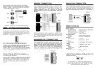
Protégé® Eclipse LED Keypad Installation Manual
Protégé® Eclipse LED Keypad Installation Manual
Protégé® Eclipse LED Keypad Installation Manual
- No tags were found...

You also want an ePaper? Increase the reach of your titles
YUMPU automatically turns print PDFs into web optimized ePapers that Google loves.
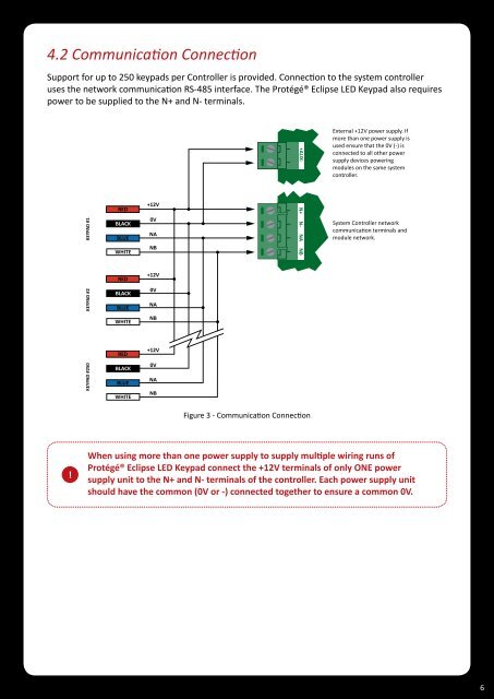
4.2 Communication ConnectionSupport for up to 250 keypads per Controller is provided. Connection to the system controlleruses the network communication RS-485 interface. The <strong>Protégé®</strong> <strong>Eclipse</strong> <strong>LED</strong> <strong>Keypad</strong> also requirespower to be supplied to the N+ and N- terminals.+-+AUX-External +12V power supply. Ifmore than one power supply isused ensure that the 0V (-) isconnected to all other powersupply devices poweringmodules on the same systemcontroller.KEYPAD #1REDBLACKBLUEWHITE+12V0VNANBN+ N- NA NBN+ N- NA NBSystem Controller networkcommunicaon terminals andmodule network.RED+12VKEYPAD #2BLACKBLUE0VNAWHITENBRED+12VKEYPAD #250BLACKBLUEWHITE0VNANBFigure 3 - Communication Connection!When using more than one power supply to supply multiple wiring runs of<strong>Protégé®</strong> <strong>Eclipse</strong> <strong>LED</strong> <strong>Keypad</strong> connect the +12V terminals of only ONE powersupply unit to the N+ and N- terminals of the controller. Each power supply unitshould have the common (0V or -) connected together to ensure a common 0V.6