Protégé® Eclipse LED Keypad Installation Manual
Protégé® Eclipse LED Keypad Installation Manual
Protégé® Eclipse LED Keypad Installation Manual
- No tags were found...

Create successful ePaper yourself
Turn your PDF publications into a flip-book with our unique Google optimized e-Paper software.
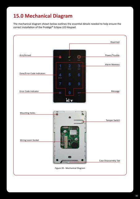
15.0 Mechanical DiagramThe mechanical diagram shown below outlines the essential details needed to help ensure thecorrect installation of the <strong>Protégé®</strong> <strong>Eclipse</strong> <strong>LED</strong> <strong>Keypad</strong>.DisarmedArm/ArmedPower/TroubleAlarm MemoryZone/Error Code IndicatorsError Code IndicatorMessageMounting HolesTamper SwitchWiring Loom SocketCase Disassembly TabFigure 20 - Mechanical Diagram30