Protégé® Eclipse LED Keypad Installation Manual
Protégé® Eclipse LED Keypad Installation Manual
Protégé® Eclipse LED Keypad Installation Manual
- No tags were found...

Create successful ePaper yourself
Turn your PDF publications into a flip-book with our unique Google optimized e-Paper software.
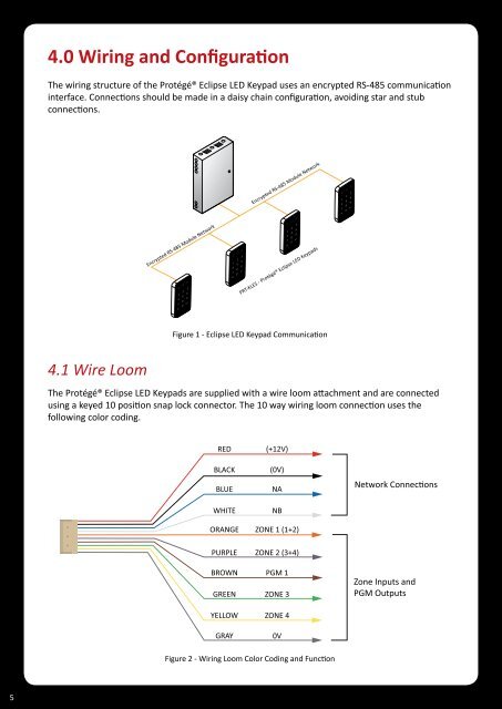
4.0 Wiring and ConfigurationThe wiring structure of the <strong>Protégé®</strong> <strong>Eclipse</strong> <strong>LED</strong> <strong>Keypad</strong> uses an encrypted RS-485 communicationinterface. Connections should be made in a daisy chain configuration, avoiding star and stubconnections.Encrypted RS-485 Module Network Encrypted RS-485 Module NetworkPRT-KLES - <strong>Protégé®</strong> <strong>Eclipse</strong> <strong>LED</strong> <strong>Keypad</strong>sFigure 1 - <strong>Eclipse</strong> <strong>LED</strong> <strong>Keypad</strong> Communication4.1 Wire LoomThe <strong>Protégé®</strong> <strong>Eclipse</strong> <strong>LED</strong> <strong>Keypad</strong>s are supplied with a wire loom attachment and are connectedusing a keyed 10 position snap lock connector. The 10 way wiring loom connection uses thefollowing color coding.REDBLACKBLUEWHITEORANGE(+12V)(0V)NANBZONE 1 (1+2)Network ConneconsPURPLEBROWNGREENYELLOWGRAYZONE 2 (3+4)PGM 1ZONE 3ZONE 40VZone Inputs andPGM OutputsFigure 2 - Wiring Loom Color Coding and Function5