Installation Manual - ICT
Installation Manual - ICT
Installation Manual - ICT
- No tags were found...

Create successful ePaper yourself
Turn your PDF publications into a flip-book with our unique Google optimized e-Paper software.
PRT-CTRL-SEProtege SE Integrated System Controller<strong>Installation</strong> <strong>Manual</strong>
The specifications and descriptions of products and services contained in this document were correct at thetime of printing. Integrated Control Technology Limited reserves the right to change specifications or withdrawproducts without notice. No part of this document may be reproduced, photocopied, or transmitted in any formor by any means (electronic or mechanical), for any purpose, without the express written permission ofIntegrated Control Technology Limited. Designed and manufactured by Integrated Control Technology Limited.Protege® and the Protege® Logo are registered trademarks of Integrated Control Technology Limited. All otherbrand or product names are trademarks or registered trademarks of their respective holders.Copyright © Integrated Control Technology Limited 2003-2013. All rights reserved.Publication Date: March 20132 PRT-CTRL-SE Protege SE Integrated System Controller <strong>Installation</strong> <strong>Manual</strong> | March 2013
Contents1 Introduction _______________________________________________________________ 51.1 Document Conventions ................................................................................................. 52 <strong>Installation</strong> Requirements ___________________________________________________ 63 Mounting _________________________________________________________________ 73.1 UL/ULC <strong>Installation</strong> Cabinet Options ............................................................................ 84 Connections ______________________________________________________________ 94.1 Protege SE Integrated System Controller Connection .................................................. 94.2 Wiring .......................................................................................................................... 104.3 Cabinet Enclosure Tamper Switch .............................................................................. 104.4 Earth Ground Connection ............................................................................................ 104.5 AC Power .................................................................................................................... 114.6 Battery Backup ............................................................................................................ 124.7 Battery Charge Current Setting ................................................................................... 134.8 Status Indicator ........................................................................................................... 134.9 Encrypted Module Network ......................................................................................... 144.10 Telephone Dialer .......................................................................................................... 164.11 Expansion Connector .................................................................................................. 164.12 Ethernet 10/100 Network Interface ............................................................................. 175 Door Access Control ______________________________________________________ 195.1 Card Reader Connection ............................................................................................. 195.2 Multiple Wiegand Card Reader Connection ................................................................ 205.3 Door Contact Connection ........................................................................................... 215.4 Lock Output Connection ............................................................................................. 225.5 Programming the Onboard Reader ............................................................................. 226 Inputs ___________________________________________________________________ 246.1 Zones ........................................................................................................................... 246.2 Resistor Value Options ................................................................................................ 256.3 Trouble Zones ............................................................................................................. 267 Programmable Outputs ___________________________________________________ 277.1 Bell/Siren PGM Outputs .............................................................................................. 277.2 PGM 3/4 Outputs ........................................................................................................ 287.3 Reader PGMs .............................................................................................................. 288 Hardware Configuration ___________________________________________________ 298.1 Configuration Switch ................................................................................................... 298.2 Defaulting a Controller ................................................................................................. 30PRT-CTRL-SE Protege SE Integrated System Controller <strong>Installation</strong> <strong>Manual</strong> | March 2013 3
9 LED Indicators ___________________________________________________________ 319.1 Status LED ................................................................................................................... 319.2 Fault Indicator .............................................................................................................. 319.3 Charge/Test Indicator .................................................................................................. 319.4 Auxiliary OK Indicators ................................................................................................ 319.5 AC OK Indicator .......................................................................................................... 319.6 5V Isolated Power Indicator ........................................................................................ 319.7 Bell 1/Bell 2 Indicators ................................................................................................. 329.8 Network RX/TX Indicators ........................................................................................... 329.9 Ethernet Link Indicator ................................................................................................ 329.10 100Mb Indicator .......................................................................................................... 329.11 R1/R2 Data Indicators ................................................................................................. 329.12 Online Indicator ........................................................................................................... 3210 Mechanical Diagram ______________________________________________________ 3311 Mechanical Layout _______________________________________________________ 3412 System Capacities ________________________________________________________ 3513 Technical Specifications ___________________________________________________ 3713.1 Current and Validation Example 1 ............................................................................... 3813.2 Current and Validation Example 2 ............................................................................... 3913.3 Maximum Total Output Current: UL and ULC <strong>Installation</strong>s ......................................... 4013.4 Current and Validation (UL <strong>Installation</strong>) Example 1 ..................................................... 4113.5 Current and Validation (UL <strong>Installation</strong>) Example 2 ..................................................... 4214 UL and ULC <strong>Installation</strong> Requirements ______________________________________ 4314.1 Central Station Signal Receiver Compatibility List ...................................................... 4314.2 ULC Compliance Requirements .................................................................................. 43CAN/ULC-S304-06 ...................................................................................................... 43CAN/ULC-S319-05 ...................................................................................................... 46CAN/ULC-S559-04 ...................................................................................................... 4614.3 UL Compliance Requirements .................................................................................... 50UL1610 ........................................................................................................................ 50UL294 .......................................................................................................................... 5115 FCC Compliance Statements ______________________________________________ 5316 Industry Canada Statement ________________________________________________ 5517 Ordering Information ______________________________________________________ 5618 Warranty ________________________________________________________________ 5719 Contact _________________________________________________________________ 584 PRT-CTRL-SE Protege SE Integrated System Controller <strong>Installation</strong> <strong>Manual</strong> | March 2013
1 IntroductionThank you for purchasing the Protege SE Integrated System Controller by <strong>ICT</strong>. The Protege System is anadvanced technology security system designed to provide integration with building automation, apartmentcomplex control and HVAC in one flexible package. Communication is over a proprietary high speed protocolacross an encrypted local area network and AES Encrypted Proprietary RS-485 module network. Usingmodular-based hardware design, system installers have the flexibility to accommodate any installation whetherit's small, large, residential or commercial.The Controller is the central processing unit of the Protege System. The Controller communicates with allsystem modules, stores all configuration and transaction information, processes all system communication, andreports alarms and system activity to a monitoring station or remote computer.Flexible module network architecture allows large numbers of modules to be connected to the RS-485 ModuleNetwork. Up to 250 modules can be connected to the Protege System in any combination to the network up toa distance of 900M (3000ft). Communication beyond this distance requires the use of a RS-485 NetworkExtenderThe current features of the Protege SE Integrated System Controller include:• Internal industry standard 10/100 Ethernet• 32 Bit advanced RISC processor with 2MB RAM and 4MB flash• 16 high security monitored zone inputs• NIST Certified AES 128, 192 and 256 Bit EncryptionWhen receiving this product you should find the kit contains the items listed below. If you do not have thecorrect contents, please contact your distributor immediately.• Protege SE Integrated System Controller• Protege SE Integrated System Controller Quick Start Guide• 6 nylon spacers• 36 1K ohm resistors• Red/black battery backup wires• 2 Diode 1N4007 1A 400V (Axial)For more information on the Protege SE Integrated System Controller and other Integrated Control Technologyproducts please visit the <strong>ICT</strong> website (http://www.incontrol.co.nz).1.1 Document ConventionsThis document uses the following conventions:iULULČ[TEXT]Important warnings or cautionary messages to prevent equipment damage, data loss, or othersimilar conditionsNotes with additional information such as an explanation, a comment, or a clarification about thesubjectTips containing practical information that may help you solve a problem or describing actions thatmay save you timeInformation relating to UL and ULC complianceBold text enclosed in brackets is used to show a section number or address of a programmableoption or information on programming shortcut sequencesPRT-CTRL-SE Protege SE Integrated System Controller <strong>Installation</strong> <strong>Manual</strong> | March 2013 5
2 <strong>Installation</strong> RequirementsThis equipment is to be installed in accordance with:• The Product installation instructions• UL 681 - <strong>Installation</strong> and Classification of Burglar and Holdup Systems• UL 827 - Central-Station Alarm Services• CAN/ULC-S301, Central and Monitoring Station Burglar Alarm Systems• CAN/ULC-S302, <strong>Installation</strong> and Classification of Burglar Alarm Systems for Financial and CommercialPremises, Safes and Vaults• CAN/ULC-S561, <strong>Installation</strong> and Services for Fire Signal Receiving Centres and Systems• The National Electrical Code, ANSI/NFPA 70• The Canadian Electrical Code, Part I, CSA C22.1• The Local Authority Having Jurisdiction (AHJ)6 PRT-CTRL-SE Protege SE Integrated System Controller <strong>Installation</strong> <strong>Manual</strong> | March 2013
3 MountingThe Protege Controller is supplied as a PCB only (printed circuit board). We recommend that gear plate styleenclosures are used wherever possible, as this provides the best mounting and installation solution as well asthe required cable entry and termination space.When installing the Controller ensure that there is adequate clearance around all sides of the cabinet enclosureand air flow to the vents of the enclosure are not restricted.It is recommended the Controller is installed in a location that will facilitate easy access for wiring. It is alsorecommended that the Controller be installed in electrical rooms, communication equipment rooms, closets orin an accessible area of the ceiling.Step 1Insert the plastic standoffs into the locations to mount the PCB board.Step 2Calculate the location and position of the cabinet enclosure and mark the holes for the keyhole points in the topleft and right locations. This will enable you to fasten the screws and then hang the box on them adjusting thelocation to suit.Step 3Ensure a solid fixing point and fasten the two screws. Before tightening the top screws, insert the tamperbracket in the slot provided on the right side of the cabinet enclosure.Step 4Fix the cabinet enclosure securely using the remaining mounting holes on the bottom left, right and centre of thecabinet enclosure.Step 5If you are extending the Protege Controller by the addition of a communications module or memory interface,insert the 4 extended nylon standoffs through the rear of the Controller.Step 6Insert the PCB into the cabinet enclosure and mount using the plastic standoffs inserted during step 1.iTo reduce the risk of damage caused by debris during the installation, install the cabinet enclosurewhen the circuit board is not installed on the plastic standoffs.PRT-CTRL-SE Protege SE Integrated System Controller <strong>Installation</strong> <strong>Manual</strong> | March 2013 7
3.1 UL/ULC <strong>Installation</strong> Cabinet OptionsUL/ULC Central Station Fire Monitoring, Central Station Alarm <strong>Installation</strong>sCabinet Model Manufacturer UL/ULC <strong>Installation</strong> ListingsD8108A Bosch UL1610, UL1635, ULC-S304, ULC-S559Electronic Access Control System <strong>Installation</strong>sULULČAll cabinet installations of this type must be located inside the Protected Area.Cabinet Model Manufacturer UL/ULC <strong>Installation</strong> ListingsCAB-LARGE-UL <strong>ICT</strong> UL294, CAN/ULC-S319D8108A Bosch UL294, CAN/ULC-S3198 PRT-CTRL-SE Protege SE Integrated System Controller <strong>Installation</strong> <strong>Manual</strong> | March 2013
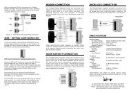
+-4 Connections4.1 Protege SE Integrated System Controller ConnectionGel CellBackupBattery(Min 7Ah)TamperSwitchCold waterearth pipeULC-LA ACIndicator*Inline5A 3AGfuseholder*The Protege ® SE Integrated SystemController shall be supplied by aTransformer: dedicated electrical power source rated16 to 16.5VACfor a minimum 10Amp load and have asecondary(via transformer) dedicated circuit breaker. Do not use aswitch controlled breaker or switchedelectrical point to supply electrical power.CAUTION: INCORRECTWIRING MAY RESULT INDAMAGE TO THE UNITProtege ® SE Integrated SystemController or module supplyingpower to networked devicesN+ N- NA NB+AUX- Z13 COM COMZ14 Z15 Z16AUX power from Moduleor external power supply8 Ohm 30WSiren or 1.1A(Maximum)8 Ohm 30WSiren or 1.1A(Maximum)LockPower Supply++ElectricLocking Device--Bracket1N4007DiodeRelay1K1K1K1K+1.1A (Maximum)ElectricLocking Device-+1.1A (Maximum)ElectricLocking Device-1k Resistors1k ResistorsN.C Zone Contact1K1KN.O Zone ContactN.C Zone Contact1K1K++T+ T- + - NO COM NCN.O Zone Contact--1N4007Diode1N4007DiodeDoor ContactREXBond SenseREN+AUX- Z1 COM COMZ2 Z3 Z4Value 1 Value 2 Monitored Status1K 1K Open, Close, Tamper, Short6K8 2K2 Open, Close, Tamper, Short10K 10K Open, Close, Tamper, Short2K2 2K2 Open, Close, Tamper, Short4K7 2K2 Open, Close, Tamper, Short4K7 4K7 Open, Close, Tamper, ShortB1+ B1- B2+ B2- P3 P4Nano Prox Reader(Optional Extra)N.CTamperShieldRedBlackGreenWhiteOrangeBrownBlueYellowTypical Zone Circuits*When installed with the power supply manufactured by Marcus (Model M4758CT), the Digital SecurityControls (DSC) Model ULC-LA power indicator light assembly (<strong>Installation</strong> Instruction No. 29001877 R0)must be installed within a conduit knockout of the <strong>ICT</strong> Model CAB-LARGE-UL or Bosch Model D8108Aenclosure in order to provide green AC power on indication. The Littelfuse Part No. 150322 fuseholderand Littelfuse Part No. 0312005 5A, 3AG fast-acting fuse must be installed in-line to the ModelsPRT-CTRL-SE, PRT-ZX16-PCB and PRT-RDI2-PCB.Servicing of theCR2032 batterymust be done by atrained technician.N.C Zone ContactValue 2 Value 1+AUX- Z1 COM COMZ2 Z3 Z4Switches 1 & 2 - Operating ModeSwitch Switch Function1 2 Power Up Boot ModeOFF OFF Normal Operation*ON OFF BOOT LoaderOFF ON BIOS UtilityON ON Reserved Do Not SetSwitch 3 - IP Address OverrideOFF Normal Operation*ON IP will be set to 192.168.111.222while this switch remains onSwitch 4 - Memory DefaultOFF Normal Operation*ON Factory Default*Default SettingZone OptionsProgrammable OutputsPGMs 3/4The PGM Outputs 3 (PGM3 CP001:03) and 4(PGM CP001:4) are Open Collector Outputs andswitch to OV. The PGM’s can be used to activaterelays, sounders and lights.LED1K5 OHMThe onboard readers ports use zone input 9 – 12 and13 - 16 as door contact, REX, bond sense and RENinputs respectively. Any of these inputs that are notused as general purpose zone inputs. Please referto the Protege ® SE Integrated System Controller<strong>Installation</strong> <strong>Manual</strong> Section 5.5 Programming theOnboard Reader.LEDStatusFaultWhiteBlueBlackRedCharge /TestAUX1 /AUX2AC5V ISOGreyBrownRedGreenLOCK1 /LOCK2BELL1 /BELL2NetworkRX / TXEthernetLinkEthernet100MbR1 / R2DataONLINEWiringSlow FlashFast FlashONOFFSlow FlashVaryingIntensityONOFFONOFFONOFFONOFFONOFF2 Flashes3 FlashesFast FlashOFFONOFFFast FlashONOFFSlow FlashFast FlashONOFFModem InterfaceSurge ProtectorEarth Ground Link connectionprovided via metallic enclosureN+ N- NA NBLED IndicatorsDescriptionProtege SystemController operating normallyController is in BIOS modeController is in BIOS modeController operating normallyupdateNext moduleson networkRJ31XBattery is being charged, indicator’s intensityshows charging currentBattery test in progressBattery is fully charged (if AC Indicator is ON)Auxiliary supply is normalAuxiliary supply is in over current protectionValid AC input providedAC is disconnected or has failedValid power supply providedPower supply disconnected or is not poweredproperlyLOCK/BELL is ONLOCK/BELL is OFFL-COMHGLN-D1DTLOCK/BELL is ON, the circuit is in over currentprotectionLOCK/BELL is OFF, the circuit to the lockingdevice is cut, damaged, or tamperedData packet transmitted/receivedNo data packet transmitted/receivedLive Ethernet connection detectedNo Ethernet connection detectedEthernet packet transmitted/receivedEthernet connection operates at 100MbEthernet connection does not operate at100MbData received in valid formatData received in invalid formatOnboard modem off hookOnboard modem not activeEARTH GND WIRING: Minimum 14AWG solid copper wire.ZONE WIRING: maximum distance of 300m (1000ft) from the Protege ®SE Integrated System Controller when using 22 AWG.AUX WIRING: Min 22AWG Max 16AWG. (Depends on length and Currentconsumption). For wire/cable size, a maximum of 5% voltage drop at theterminals of the powered device has to be observed.ETHERNET WIRING: CAT5e / CAT6 max 100m (330 ft)MODULE NETWORK WIRING: Recommended Belden 9842 or equivalent.(24AWG twisted pair with characteristic impedance of 120ohm or CAT5e /CAT6 are also supported for Data Transmission when using ground in thesame cable. Do not use extra wires to power devices.) max 900m (3000ft).PRT-CTRL-SE Protege SE Integrated System Controller <strong>Installation</strong> <strong>Manual</strong> | March 2013 9
4.2 WiringCAUTION: Incorrect wiring may result in damage to the unit.• All output circuits comply with the requirements for inherent power limitation and are Class 2except the battery wires and AC wires which are not power limited.• A minimum of 1/4" (6.35mm) physical separation must be respected between power limited andnon power limited wiring (Battery Wires and AC Wires).• Do not route any wiring over circuit board. Maintain at least 25.4mm (1") separation.• The connection to the mains supply must be made as per local authorities rules and regulations.4.3 Cabinet Enclosure Tamper SwitchThe cabinet enclosure tamper input sends a signal to the monitoring station or remote computer when thecabinet enclosure has been opened. The tamper input switch shall be mounted into the steel bracket providedand connected to the tamper connection terminals as shown below.Tamper SwitchBracketAC AC ST TP TPTamper Input Connection4.4 Earth Ground ConnectionThe Controller has a connection for earth ground. For best results, a cold water pipe should be used with a pipewiring clamp. If a cold water pipe is not available, connect to a suitable ground connection in the installation. Aminimum 14AWG solid copper wire shall be used from the Controller's earth connection point to the clamp onthe cold water pipe. If other earth clamps are present at the same connection point, connect the clamp belowthe existing units.Cold water pipe grounding earthpeg grounding rodTo other earth connecons alreadyaached to the earth peg or waterpipeAC AC ST TP TPEarth Ground Connection10 PRT-CTRL-SE Protege SE Integrated System Controller <strong>Installation</strong> <strong>Manual</strong> | March 2013
4.5 AC PowerThe Protege Controller shall be supplied by a dedicated electrical power source rated for a minimum 10Ampload and have a dedicated circuit breaker. Do not use a switch controlled breaker or a switched electrical pointto supply electrical power. Connect the primary (120VAC) of a 16 to 16.5 VAC, 60Hz, 40VA or 100VAtransformer (refer to the table below) to the electrical circuit and run the secondary (16 to 16.5VAC) to the ACInput on the Controller terminals.ULULČThe following table outlines the transformers that shall be used in order to comply with UL and ULCinstallation standards.When installed with the power supply manufactured by Marcus, Model M4758CT:• the Digital Security Controls (DSC) Model ULC-LA power indicator light assembly (<strong>Installation</strong>Instruction No. 29001877 R0) must be installed within a conduit knockout of either the <strong>ICT</strong> ModelCAB-LARGE-UL or Bosch Model D8108A enclosure in order to provide green AC power onindication.• the Littelfuse Part No. 150322 fuseholder and Littelfuse Part No. 0312005 5A, 3AG fast-actingfuse must be installed in-line to the Models PRT-CTRL-SE, PRT-ZX16-PCB, and PRT-RDI2-PCB.For ULC Central Station Fire Monitoring installations, a hardwired connection type transformer isrequired. Check with the local authority.Transformer Manufacturer Transformer Type SpecificationTRI-PIT 1640C Solex PLUG IN Transformer 16.5VAC 40VANE-TP4016L National Electronics PLUG IN Transformer 16.5VAC 40VAGF-4016L GFX PLUG IN Transformer 16.5VAC 40VAM4758CT MARCUS HARDWIRE Transformer (requires Class 1120VAC input)16VAC 100VAMains InputTransformerULC-LAIn line fuseholder 3AG 5AAC AC ST TP TP*Littelfuse 150322 fuse holderand 312 fuse 5A 3AG fast-actingAC Power ConnectionSpecific regional regulations may allow the transformer to be mounted inside the cabinet enclosure. In this casewire the electrical circuit to the electrical termination point inside the cabinet enclosure and the secondary wiresof the transformer to the AC Input on the Controller. The earth wire shall be routed to the terminal on theController when using an internal transformer.Warning:• This installation should be made by qualified service personnel and should conform to all localcodes and in accordance with the National Electrical Codes (NEC US) or the Canadian ElectricalCodes (CEC Canada).• Termination of wiring to the Controller while power is applied or the battery is connected maycause serious damage to the Controller and will VOID ALL WARRANTIES OR GUARANTEES.Power the unit only after all wiring, configuration and jumper settings are completed.• Extra care must be taken when wiring the AC inputs. Improper connection will cause permanentdamage to the Controller.PRT-CTRL-SE Protege SE Integrated System Controller <strong>Installation</strong> <strong>Manual</strong> | March 2013 11
4.6 Battery BackupIt is recommended that a minimum of a 7Ah battery is used as the main battery backup. From the accessorybag provided, connect the battery housing connector to the battery connector on the Controller. Connect thespade terminals to the battery as shown in the diagram below. Connection of the battery in reverse will notdamage the Controller but will cause the electronic battery fuse (5A fast blow) to open. Prolonged reverseconnection can cause damage to the Controller.ULULČPlease refer to the section Maximum Total Output Current : UL and ULC <strong>Installation</strong>s for specificrequirements on complying with UL and ULC installation standards.Servicing of the battery circuit and replacement of lithium battery must be done by a trainedtechnician.Follow battery manufacturer instructions for installation, testing and maintenance.AC AC ST TP TP+-+ _BATTGel Cell Backup BaeryBattery ConnectionThe battery test procedure uses a special algorithm to prevent deep discharge and increase battery endurance.A dynamic battery test is performed every ten minutes (default) when AC power is present. A battery troublezone alarm will be generated if the battery is either disconnected or shows poor capacity. Battery faultconditions will activate the battery trouble zone.If AC is not present, the Controller will monitor the battery for a low voltage level and will activate the batterytrouble zone. The next dynamic battery test will occur 30 minutes after AC power has been restored. This delayallows the battery to achieve optimal charging during the first 30 minutes that power has been restored to theunit. Once the first test is completed the dynamic testing will return to the programmed value (default 10minutes).When power is first applied to the Controller, a dynamic battery test will be performed after 30 seconds. Thisallows the status and condition of the battery to be detected. On completion of this first test, the default testingperiod of 10 minutes will be resumed. This is a programmable setting in the Controller panel options. The testperiod can be changed as required by setting the battery test time in the Controller Configuration Menu.Warning: Only attach standard lead acid batteries. Do not connect the battery wires or batteryhousing connector of the Controller to any other ancillary device (siren, lock or mag clamp etc).Connection may cause erroneous faults or serious damage to the Controller and will VOID ALLWARRANTIES OR GUARANTEES.12 PRT-CTRL-SE Protege SE Integrated System Controller <strong>Installation</strong> <strong>Manual</strong> | March 2013
4.7 Battery Charge Current SettingTo configure the Controller manually for the charge current, select the appropriate battery current limit settingusing the jumpers as shown below.350mA700mABattery Charge JumperJumper Location4.8 Status IndicatorThe status output will activate according to the status indicator on the Controller and can be used to providesignalling or indication of the Controller status outside the enclosure. The following diagrams show theconnection of an LED indicator to the status output.+12V AUXLED1K5 OHMAC AC ST TP TPExternal Status LED ConnectionPRT-CTRL-SE Protege SE Integrated System Controller <strong>Installation</strong> <strong>Manual</strong> | March 2013 13
4.9 Encrypted Module NetworkThe Controller incorporates technically advanced encrypted RS-485 communications technology. The isolatedcommunications interface offers full galvanic isolation to prevent ground loop noise and cross phase grounddifferential. The communication offers superior interference immunity. Connection of the communications shallbe performed according to the following diagram.N+ N- NA NBNetwork communicaons inputfrom the Protege IntegratedSystem Controller or previousProtege moduleStandard Communication ConnectionAlways connect the Controller's NA and NB terminals to the NA and NB terminals of the expansion devices andkeypads. The N+ and N- must go to a 12V power supply source as shown below.+AUX- Z1 COM Z2 Z3 COM Z4AUX power from Module orexternal power supplyProtege Integrated SystemController or module supplyingpower to networked devicesN+ N- NA NBN+ N- NA NBN+ N- NA NBNext moduleson networkNetwork Power ConnectionThe above diagram shows a power connection taken from the auxiliary power outputs on the Controller's zoneterminals.This connection is suitable for smaller systems provided that the:• Maximum total output current,• AUX DC output current,• B1/B2 DC output current, and• Total combined currentare ALL lower or equal to the values outlined in the Technical Specifications section. If these currents areexceeded, a separate power supply shall be used.14 PRT-CTRL-SE Protege SE Integrated System Controller <strong>Installation</strong> <strong>Manual</strong> | March 2013
ULULČIf an external power supply is required, a UL 603 or UL 294 listed power-limited power supply must beused to comply with UL installation standards, and a CAN/ULC-S318 or CAN/ULC-S319 listedpower-limited power supply must be used to comply with ULC installation standards.Warning: The 12V N+ and N- communication input must be supplied from only one point.Connections from more than one 12V supply may cause failure or damage to the units supplyingpower.The recommended module network wiring specifications are:• CAT5e / CAT6 are also supported for data transmission when using ground in the same cable.• 24AWG twisted pair with characteristic impedance of 120ohm• Belden 9842 or equivalent.• Maximum total length of cable is max 900m (3000ft)Warning: Unused wires in the cable must not be used to carry power to other devices.Shielded Cables• Shielded cables can be used in noisy environments (with RF and electromagnetic interference).• If a shielded cable is used, the shield must be connected at only one end of the cable. DO NOT connect ashield at both ends. Refer to the following diagram for the recommended shield connection.Product #1 Product #2 Product #3N+ N- NA NB N+ N- NA NB N+ N- NA NBShielded CableShielded CableShield is framegrounded atone pointShields areconnected togetherand IsolatedShield notconnectedExternal Power Supplyor AUX Supply OutRecommended Shield ConnectionEOL OFFEOL ONEOL JumperiThe EOL (End Of Line) jumper setting must be set in the on position for the first and last expansiondevice only.PRT-CTRL-SE Protege SE Integrated System Controller <strong>Installation</strong> <strong>Manual</strong> | March 2013 15
4.10 Telephone DialerThe Controller provides the ability to communicate alarms and upload/download information with remotesystems using the onboard 2400bps modem. The telephone line can be connected directly to the Controllerusing the onboard telephone connection terminals.T1i R1i T1o R1oTelco line outTelco line p and ring inputTelephone Line ConnectionULULČFor UL/ULC installations, a Modem Surge Protection Interface must be used.4.11 Expansion ConnectorThe Controller has an onboard expansion connector that is used to connect serial communication, memory andspecial function interface devices. Connect the interface card to the Controller as shown in the followingdiagrams. For configuration information, refer to the Protege Reference <strong>Manual</strong> and the installation instructionsprovided with the interface device.Expansion Connector and Mounting Hole LocationWhen installing the daughter board, ensure that the plastic mounting hardware provided is correctly insertedfrom the rear of the Controller. Pay attention to the key location of the 40 Way connector.40 WayExpansion ConnectorDaughter BoardMain System ControllerConnection and Mounting16 PRT-CTRL-SE Protege SE Integrated System Controller <strong>Installation</strong> <strong>Manual</strong> | March 2013
Warning: Power to the Protege System Controller must be turned off when connecting any hardwareor system device to the Controller. Failure to do so may damage the Protege System Controller andexpansion device.iIf the Protege System Controller is used with the expansion connector fitted, the second onboardreader port becomes unavailable.ULULČ40 Way expansion connector communication has not been evaluated by UL/ULC.4.12 Ethernet 10/100 Network InterfaceThe communication between the Protege System and the Controller uses a 10/100 Ethernet network operatingthe TCP/IP protocol suite. The IP address of the Controller can be configured using the LCD Keypad Terminal.The default IP address is set to a static IP address of 192.168.1.2 with a subnet mask of 255.255.255.0. TheseIP address settings are commonly used for internal networks.iInstalling the Protege System Controller on an active network requires knowledge of the configurationand structure for the network. Always consult the network or system administrator and ask them toprovide you with a fixed IP address that can be assigned to the Protege System Controller.When the IP address has previously been set and is not known you are able to set configuration DIPswitch 3 which on power-up of the Protege System Controller will configure the IP address to192.168.111.222. This will allow access to the configuration utility to change or review theprogrammed IP Address.When installing an Ethernet connection the Protege System Controller shall be interfaced using a standardsegment (
Temporary direct connections can be used for onsite programming by connecting directly to the computerEthernet port.Ethernet 10/100 Direct ConnectionULULČ• All network equipment such as hub/router/gateway used with the Protege System Controller mustcomply with the UL and ULC standard requirements associated with a signal receiving center.• The Protege System Controller must be installed in the same room as the network equipment thatprovides it the network connection.18 PRT-CTRL-SE Protege SE Integrated System Controller <strong>Installation</strong> <strong>Manual</strong> | March 2013
5 Door Access ControlThe Controller provides access control functionality onboard without the requirement for additional hardware.With 2 access controlled doors built in, the flexibility of the Protege system is expanded even further. TheController allows the connection of 2 Wiegand devices to control 2 doors (entry or exit only) or can beconfigured in multiplex mode to allow 4 Wiegand devices controlling 2 doors giving the flexibility of entry and exitreaders.5.1 Card Reader ConnectionThe following diagram shows the connection of a standard Wiegand Reader with the Controller controlling anaccess door in entry or exit mode (2 doors, 2 readers).+AUX- Z9 COM Z10 Z11 COM Z12 D0 D1 L1 BZREDShielded CableBLACKGREENWHITEN/RORANGE* See TextN/R = Not RequiredShield is framegrounded atone pointShield notconnectedBROWNBLUEN/RYELLOW*SHIELDCard Reader ConnectionThe card reader must be connected to the Controller port using a shielded cable. Always refer to the cardreader manufacturer for detailed installation guidelines. The shield connection must only be connected at oneend of the cable in the metallic enclosure(frame grounded). The beeper output on the Controller providesdiagnostic information to the end user and installer when access is denied or the unit is operating offline.Warning:• Do not connect the shield to a AUX- or 0V connection.• Do not join the shield and black wires at the reading device.• Do not connect the shield to any shield used for isolated communication.i• If the Controller is used with the expansion connector fitted, the second onboard reader portbecomes unavailable.• The Controller does not support dual LED reader mode and readers must be configured for singleLED mode. Refer to your card reader documentation for further details.ULULČCompatible access control card reader communication formats are: 26-, 34-, 37-Bit Wiegand,RS-232, RS-485, and Smart RS-485.PRT-CTRL-SE Protege SE Integrated System Controller <strong>Installation</strong> <strong>Manual</strong> | March 2013 19
5.2 Multiple Wiegand Card Reader ConnectionWhen operating the Controller in multiple reader mode, the Controller allows the connection of 4 Wiegandreading devices controlling two doors each with entry/exit readers.When connecting Wiegand readers in multiple reader mode, the secondary reader that is connected will have allconnections wired to the same port as the primary card reader with the DATA 1 connection wired to theopposite reader connection DATA 1 input.+AUX- Z9 COM Z10 Z11 COM Z12 D0 D1 L1 BZ D0 D1 L2 BZ*SHIELDREDShielded CableBLACKGREENWHITEN/RORANGE* See TextN/R = Not RequiredShield is framegrounded atone pointBROWNBLUEN/RYELLOW*SHIELDREDShielded CableBLACKGREENWHITEN/RORANGEShield notconnectedBROWNBLUEN/RYELLOWMultiple Wiegand Card Reader ConnectionThe card reader must be connected to the Controller port using a shielded cable. Always refer to the cardreader manufacturer for detailed installation guidelines. The shield connection must only be connected at oneend of the cable in the metallic enclosure(frame grounded). The beeper output on the Controller providesdiagnostic information to the end user and installer when access is denied or the unit is operating offline. Thereader that is multiplexed into the alternate reader port will operate as the exit reader and the normal readerconnection shall be programmed to operate as the entry reader.Warning:• Do not connect the shield to a AUX- or 0V connection.• Do not join the shield and black wires at the reading device.• Do not connect the shield to any shield used for isolated communication.20 PRT-CTRL-SE Protege SE Integrated System Controller <strong>Installation</strong> <strong>Manual</strong> | March 2013
5.3 Door Contact ConnectionThe Controller allows the connection of up to 4 contacts for monitoring and controlling access control doors.Each zone on the reader expander can be used for the door function that is automatically assigned and as anormal zone input on the system. The following example shows the connection of a normally closed doorposition monitoring contact to monitor the Open, Closed, Forced and Alarm conditions of the door.N.C Zone Contact1K 1K Door Contact1K 1K REXN.O Zone ContactN.C Zone Contact1K 1K Bond Sense+AUX- Z9 COM COMZ10 Z11 Z121K 1K RENN.O Zone ContactDoor Contact ConnectionThe zones 9-12 and 13-16 can operate as either general purpose zone inputs or as onboard reader inputs. Ifused as general purpose zone inputs, make sure that these inputs are not defined in the onboard reader set up.Zone Access Control Function Default SettingZone 9 Door Contact, Port 1 Door Contact, Port 1Zone 10 REX Input, Port 1 REX Input, Port 1Zone 11 Bond Sense, Port 1 General Purpose ZoneZone 12 REN Input, Port 1 General Purpose ZoneZone 13 Door Contact, Port 2 Door Contact, Port 2Zone 14 REX Input, Port 2 REX Input, Port 2Zone 15 Bond Sense, Port 2 General Purpose ZoneZone 16 REN Input, Port 2 General Purpose ZoneULULČWhen zone inputs are configured as bond sense and/or general purpose zones (access control andburglar installations), remaining zone inputs cannot be used for fire.iWhen connected, the REX Input can be programmed to operate regardless of the door contact state.The REX input can also be programmed to recycle the door alarm time to prevent nuisance alarmswhen the door is held open to permit longer entry.PRT-CTRL-SE Protege SE Integrated System Controller <strong>Installation</strong> <strong>Manual</strong> | March 2013 21
5.4 Lock Output ConnectionThe Controller provides a connection for 2 electric strike locks with full monitoring of the lock circuit for tamperand over current/fuse blown conditions. The door lock monitoring can be disabled if it is not required.Lock outputs are shared with the bell/siren functions as shown in the diagram below. You can select anotheroutput for the lock control (P3 or P4) if the bell/siren function is required. To use the lock outputs in conjunctionwith the onboard reader module, the Lock PGM for the door associated with the reader port must be configuredto be the desired lock output on the controller. This is not configured by default.+-12VDC ElectricLocking Device1N4007 DiodeB1+ B1- B2+ B2- P3 P4Lock Output ConnectionWhen using a door with an Entry and Exit Reader, the lock output shall be connected to Bell 1, and enable theswap lock option for the second reader input to allow the reader LEDs to display the correct status.iThe total combined current must not exceed 2.5A or electronic shutdown will be engaged. Ensure thedevices connected to the outputs are within the limits as detailed in the Technical Specifications.5.5 Programming the Onboard ReaderThe onboard reader is programmed in exactly the same way as any other reader module is. It can be thought ofas if it were a normal reader expander module on a separate circuit board. By default the onboard reader isregistered as the last reader in the defined profile (which is Reader Expander 008 in the Standard profile).Consequently any reader expander module that is connected with the same address as this will be treated as aduplicate and will fail to register. To change the address at which the onboard reader is registered, or to disableit, please refer to the Controller Programming Guide.The onboard reader uses zone inputs 9-12 and 13-16 as its door contact, REX, bond sense and REN inputsrespectively. Any of these inputs that are not configured for use with the onboard reader may be used asgeneral purpose zone inputs. To use these inputs as controller zones, you will need to disable the associatedfunction input in the Controller | Modules | Reader Modules section of the Protege Software Management Suite.Alternatively, these can be disabled from the keypad by logging in as an installer and selecting Menu, 4, 1, 4,RD004.ULULČREX and REN devices must be Listed to UL 294 for UL installations and CAN/ULC-S319 for ULCinstallations, and be compatible with the system.22 PRT-CTRL-SE Protege SE Integrated System Controller <strong>Installation</strong> <strong>Manual</strong> | March 2013
The default settings are shown in the following table:Zone Access Control Function Default SettingZone 9 Door Contact, Port 1 Door Contact, Port 1Zone 10 REX Input, Port 1 REX Input, Port 1Zone 11 Bond Sense, Port 1 General Purpose ZoneZone 12 REN Input, Port 1 General Purpose ZoneZone 13 Door Contact, Port 2 Door Contact, Port 2Zone 14 REX Input, Port 2 REX Input, Port 2Zone 15 Bond Sense, Port 2 General Purpose ZoneZone 16 REN Input, Port 2 General Purpose ZoneReader Expander PropertiesPRT-CTRL-SE Protege SE Integrated System Controller <strong>Installation</strong> <strong>Manual</strong> | March 2013 23
6 Inputs6.1 ZonesThe Controller has 16 zone inputs. The Controller also monitors 64 trouble zones used to report troubleconditions. A trouble zone represents a trouble condition within the system. The trouble zone will open or go into alarm when that trouble condition is present, and close or return to normal when the trouble conditionrestores. As an example, trouble zone CP001:01 will open or go in to alarm when the tamper input on theController is open.The Controller can monitor and control thousands of zone and trouble zone inputs by using the expansionmodules.The Controller can monitor the state of up to 16 zone inputs such as magnetic contacts, motion detectors andtemperature sensors. Devices connected to these zones can be installed to a maximum distance of 300m(1000ft) from the Controller when using 22 AWG. The Controller supports normally opened and normally closedconfigurations with or without EOL resistors.ULULČ• Magnetic contacts shall be listed to UL 634 to comply with UL installation standards andULC/ORD-C634 to comply with ULC installation standards.• Motion detectors and temperature sensors shall be listed to UL 639 to comply with UL installationstandards and ULC-S306 to comply with ULC installation standards.• The PRT-CTRL-SE has been evaluated for UL 294, UL 1610, UL 1635, CAN/ULC-S304,CAN/ULC-S319 and CAN/ULC-S559.Zones can be programmed from the Protege Alphanumeric LCD Keypad (PRT-KLCD) or using the ProtegeSystem Management Suite application (PRT-SMGT). CP001:01 to CP001:16 represent zone 1 to zone 16 onthe Controller.When using a zone with the EOL resistor configuration, the Controller generates an alarm condition when thestate of a zone is toggled and generates a tamper alarm condition when a wire fault (short circuit) or a cut(tampered) in the line occurs.Zones default to require the EOL resistor configuration.N.C Zone ContactN.C Tamper 1K 1K+AUX- Z1 COM COMZ2 Z3 Z4EOL Resistor Zone ConfigurationiThe zones 9-12 and 13-16 can operate as either general purpose zone inputs or as onboard readerinputs. If used as general purpose zone inputs then make sure that these inputs are not defined in theonboard reader set up.24 PRT-CTRL-SE Protege SE Integrated System Controller <strong>Installation</strong> <strong>Manual</strong> | March 2013
Each zone input can use a different input configuration. To program a large number of zones with a certainconfiguration use the multiple selection feature in the Protege System Management Suite application.When using the No Resistor configuration, the Controller only monitors the opened and closed state of theconnected input device generating the alarm and seal conditions.N.C Zone Contact+AUX- Z1 COM COMZ2 Z3 Z4No EOL Resistor Zone Configuration6.2 Resistor Value OptionsWhen using the EOL resistor configuration, the EOL resistor option must be configured based on the siterequirements. Note that not all resistor options are supported on all Protege field modules. (Refer to ZonesSection in the Protege Reference <strong>Manual</strong>).Value 1 Value 2 Monitored Status1K - Open, Closed
6.3 Trouble ZonesEach Controller can monitor up to 64 local trouble zones. Trouble zones are used to monitor the status of theController and in most cases are not physically connected to an external zone. For example, trouble zoneCP001:03 is used to monitor the Controller's backup battery voltage and warn the Controller that the battery isdisconnected or voltage is too low. This can then be used to report a message to a monitoring station, remotecomputer, keypad or siren.The following table details the trouble zones that are configured in the Controller. The trouble type and groupdefine the trouble that is generated by the trouble zone when it is activated.Zone Number Description Type GroupCP001:01 Module Tamper System Tamper SystemCP001:02 AC Failure Power Fault GeneralCP001:03 Low Battery Power Fault GeneralCP001:04 Real Time Clock Not Set RTC/Clock Loss GeneralCP001:05 Service Report Test * *CP001:06 Service Report Failure to Communicate Reporting Failure GeneralCP001:07 Phone Line Fault Phone Line Lost GeneralCP001:08 Auxiliary Failure Power Fault GeneralCP001:09 Bell 1 Cut/Tamper Bell/PGM Fault GeneralCP001:10 Bell 2 Cut/Tamper Bell/PGM Fault GeneralCP001:11 Bell 1 Cut/Tamper Bell/PGM Fault GeneralCP001:12 Bell 2 Cut/Tamper Bell/PGM Fault GeneralCP001:13 Module Communication Module Loss SystemCP001:14 Module Network Security Module Security SystemCP001:15 Expansion Device Missing Hardware Fault SystemCP001:16 Communication Port 1 Fault Hardware Fault SystemCP001:17 Communication Port 2 Fault Hardware Fault SystemCP001:18 Ethernet Hardware Fault Hardware Fault SystemCP001:19 Ethernet Link Lost Hardware Fault SystemCP001:20 DVAC Line Fault/Polling Error Hardware Fault SystemCP001:21 ModBUS Communication Fault Hardware Fault SystemCP001:22 Protege System Remote Access Hardware Fault SystemCP001:23 Installer Logged In Hardware Fault SystemCP001:24 Service 1 Stopped Hardware Fault SystemCP001:25 Service 2 Stopped Hardware Fault SystemCP001:26 Service 3 Stopped Hardware Fault SystemCP001:27 Service 4 Stopped Hardware Fault SystemCP001:28 Reserved * *| | | | | | | |CP001:64 Reserved * *26 PRT-CTRL-SE Protege SE Integrated System Controller <strong>Installation</strong> <strong>Manual</strong> | March 2013
7 Programmable OutputsThe Controller has 8 programmable outputs (PGMs). The PGMs are used to activate sirens, bells, warningdevices, control lighting and doors. The first 2 PGMs on the Controller have special hardware designs thatallows them to monitor for fault conditions and are ideally suited to driving sirens and warning devices.7.1 Bell/Siren PGM OutputsThe + and - terminals of Bell 1 (PGM1 CP001:01) and Bell 2 (PGM2 CP001:02) are used to power bells, sirensor any devices that require a steady voltage output. The bell outputs supply 12VDC upon alarm and supportone 30-watt siren. The bell output uses a electronically fused circuit and automatically shuts down under faultconditions.ULULČNot investigated by UL/ULC for Local Burglary applications+-12VDC sirenwarning device1k ResistorsB1+ B1- B2+ B2- P1 P2Bell Siren PGM 1/2 ConnectionIf the load on the bell terminals returns to normal, the Controller reinstates power to the bell terminals on thenext transition of the output.i• When the bell output is not used, the appropriate trouble zone will be activated (refer to thesection on Trouble Zones (see page 26)). This can be avoided by connecting a 1K resistor(provided in the accessory bag) across the bell output. If the bell is not being used for anotherfunction, and the trouble zone is not programmed in the system, a resistor is not required.• Connecting a Piezo siren may result in a dull noise being emitted. This is caused by residualcurrent from the monitoring circuit. To prevent this occurring, connect 2 1K resistors in parallel.PRT-CTRL-SE Protege SE Integrated System Controller <strong>Installation</strong> <strong>Manual</strong> | March 2013 27
7.2 PGM 3/4 OutputsThe PGM outputs 3 (PGM3 CP001:03) and 4 (PGM4 CP001:04) on the Controller are open collector outputsand switch to 0V. The PGMs can be used to activate relays, sounders and lights.+AUX- Z1 COM COMZ2 Z3 Z4LED1K5 OHMB1+ B1- B2+ B2- P3 P4Open Collector PGM 3/4 ConnectionWarning: The PGM 3 and 4 outputs can switch to a maximum capacity of 50mA. Exceeding thisamount will damage the PGM output.7.3 Reader PGMsIf readers are not attached to the reader ports then the Reader 1, L1 and BZ and the Reader 2, L1 and BZoutputs can be used as general purpose PGMs. These can be controlled by assigning the RDxxxGreen R1,RDxxx Beeper R1, RDxxxGreen R2 and RDxxx Beeper R2 PGMs of whichever reader module has beenconfigured as the onboard reader module.+AUX- Z1 COM COMZ2 Z3 Z4LED1K5 OHMD0 D1 L1 BZReader PGMs28 PRT-CTRL-SE Protege SE Integrated System Controller <strong>Installation</strong> <strong>Manual</strong> | March 2013
8 Hardware Configuration8.1 Configuration SwitchThe Controller uses a 4 way dual inline dip switch located in the centre of the PCB board. This switch is used toconfigure the boot up and power on settings for the Controller. Each of the switch positions performs a differentfunction. For normal operation, all switches shall be in the off position.1234OFFONBOOT MODE 1BOOT MODE 2BIOS COMMUNICATIONDEFAULT CONTROLLERConfiguration SwitchSwitch Switch Function1 2 Power Up Boot ModeOFF OFF Normal OperationON OFF BOOT LoaderOFF ON BIOS UtilityON ON Reserved Do Not SetSwitch Switch Function3 - IP Address ConfigurationOFF - Programmed IP ConfigurationON - IP will be set to 192.168.111.222 while this switch remains on.Allows the connection and review of the programmed IP address orthe modification to another setting.Switch Switch Function4 - System DefaultOFF - Normal OperationON - Factory Default Protege ControllerPRT-CTRL-SE Protege SE Integrated System Controller <strong>Installation</strong> <strong>Manual</strong> | March 2013 29
8.2 Defaulting a ControllerThe Controller can be set back to factory default using the following procedures. This resets all internal data andevent information.Step 1Remove power from the controller by disconnecting the AC and battery supply.Step 2Turn ON configuration dip switch 4.Step 3Power up the Controller by turning on the AC supply.Step 4Turn OFF configuration dip switch 4 once the Controller is indicating normal status by flashing the green statusindicator. The system will now be defaulted with all programming and settings returned to factory configuration.iDefaulting the Controller does not reset the IP address. To reset an IP address, refer to the details onthe Configuration Switch (see page 29).30 PRT-CTRL-SE Protege SE Integrated System Controller <strong>Installation</strong> <strong>Manual</strong> | March 2013
9 LED IndicatorsThe Controller includes extensive diagnostic indicators that can aid the installer in diagnosing faults andconditions. In some cases an indicator may have multiple meanings depending on the status indicator display.9.1 Status LEDThe Status indicator is located in the centre of the PCB and indicates the status of the Controller. If theController is operating normally the LED will indicate this by flashing at 1 second intervals.9.2 Fault IndicatorThe Fault indicator is located in the centre of the PCB. During normal operation the fault indicator is off. Flashingon will indicate that the Controller is operating in firmware update mode and requires firmware to bedownloaded.9.3 Charge/Test IndicatorThe Charge/Test indicator serves two functions. It indicates that a battery test is in progress and also thatbattery charging is being performed. When AC is present, the battery charging current will be indicated by avarying intensity level on this indicator. This indicator will also illuminate when a battery test is in progress byilluminating brightly for 30 seconds every 10 minutes. The battery test period is a programmable option in theController system options.This LED is identified by the text CHARGE/TEST. This indicator does not function when AC is not present.9.4 Auxiliary OK IndicatorsAuxiliary voltage is supplied to the AUX1 and AUX2 outputs through two separate auxiliary fuses. If auxiliarysupplies are normal, both the AUX1 OK and AUX2 OK indicators will be illuminated.9.5 AC OK IndicatorWhen a valid AC input is provided to the Controller the AC OK indicator will illuminate.9.6 5V Isolated Power IndicatorThe module communicates using an isolated RS-485 interface for optimal performance and this requires anisolated supply on the N+ and N- terminals of the module network interface. When a valid supply is input, the 5VISO indicator will illuminate.PRT-CTRL-SE Protege SE Integrated System Controller <strong>Installation</strong> <strong>Manual</strong> | March 2013 31
9.7 Bell 1/Bell 2 IndicatorsThe Bell 1/Bell 2 indicators show the status of the bell output and the over current or circuit fault conditions.Bell StatusOFFONTwo FlashesThree FlashesDescriptionBell is connected, the output is OFFBell is ONBell is ON, the circuit is in over current protectionBell is OFF, the circuit to the siren/bell is cut, damaged or tampered9.8 Network RX/TX IndicatorsThe Receive and Transmit Data indicators are located on the right side of the PCB beside the communicationinterface and below the modem circuitry. The indicator shows when the Controller is transmitting and receivinginformation from the module communications interface and is identified by the text RX and TX.9.9 Ethernet Link IndicatorThe Ethernet Link indicator is located next to the ethernet connector and is labeled LINK ACT. It will be on whenthe ethernet connection has a valid link with a hub, switch, or is directly connected to a personal computer. Ifthe link indicator is off the ethernet cable is not connected.The Link Act indicator will flash for a period of 600 milliseconds when the ethernet interface receives or sends avalid frame.9.10 100Mb IndicatorThe 100Mb indicator is located next to the ethernet connector and is labeled 100. It will be on when thenetwork communication has been successfully negotiated to operate at 100Mbs.9.11 R1/R2 Data IndicatorsThe R1/R2 Data indicators are located above the Reader 1 and Reader 2 connection terminals. A short flash(1 second) indicates that the unit has read the data and the format was correct.9.12 Online IndicatorThe Online indicator is located near the center of the PCB and is labeled ONLINE. The Online indicator showswhen the modem has control of the telephone line.32 PRT-CTRL-SE Protege SE Integrated System Controller <strong>Installation</strong> <strong>Manual</strong> | March 2013
10 Mechanical DiagramThe mechanical diagram shown below outlines the essential details needed to help ensure the correctinstallation of the Protege Controller.Isolated COMMSEOL JumperMounng Holes350mA/700mA Jumper16V AC InputRS-485 NetworkCabinet Tamper InputBaery InputTelephone DialerBell/Siren OutputsPGM 3/4 OutputsConfig Switch10/100 EthernetEthernet Status LEDsFault/Status LEDPart NumberZones 1 to 4Coin Cell BaeryExpansion InterfaceZones 5 to 8Zones 9 to 12Reader Port 1Zones 13 to 16Reader Port 2Mechanical DiagramPRT-CTRL-SE Protege SE Integrated System Controller <strong>Installation</strong> <strong>Manual</strong> | March 2013 33
11 Mechanical LayoutThe mechanical layout shown below outlines the essential details needed to help ensure the correct installationof the Protege Controller.183mm175mm76.5mm98.5mm2mm5mm diameter112.2mm234mm225mmPRT-CTRL-SE113.6mm93.5mm81.5mmMechanical Layout34 PRT-CTRL-SE Protege SE Integrated System Controller <strong>Installation</strong> <strong>Manual</strong> | March 2013
12 System CapacitiesThe Protege Controller can be profiled to allow a comprehensive solution that allows optimal performance to beachieved in any installation.Standard Access Elevator School Storage Automation ApartmentUsers 2000 10000 2000 2000 500 2000 2000User Names 2000 2000 0 2000 500 2000 2000Events 2000 4000 2000 4000 4000 1000 2000Areas 32 32 64 64 128 64 248Doors 16 128 64 16 16 64 4Keypad Modules 32 16 8 8 8 32 48Analog Expanders 8 8 8 8 8 16 8Zone Expanders 16 8 4 32 64 8 4Reader Expanders 8 64 32 16 8 32 4Output Expanders 8 8 8 8 32 8 2Zone Inputs 464 720 368 688 624 528 1104Trouble Zone Inputs 704 1408 800 768 832 1088 2224PGM Outputs 420 772 468 452 772 612 1108PGM Groups 128 128 28 28 248 128 128Area Groups 32 32 64 64 248 64 248Menu Groups 16 16 16 16 16 16 16Door Groups 128 248 28 32 16 16 16Keypad Groups 32 16 8 8 8 8 8Access Levels 128 248 248 32 248 64 16Zone Types 128 128 32 28 248 64 16Door Types 8 8 8 8 8 8 4Services 8 8 8 8 4 8 4Phone Numbers 16 16 16 16 8 8 8Schedules 128 248 48 28 64 32 32Holidays 32 32 32 32 32 32 8Daylight Saving Adjustment Settings 1 1 1 1 1 1 1Automation Points 32 32 32 32 16 248 8Panel Configuration Information 1 1 1 1 1 1 1Area Names 32 32 64 64 128 64 248Access Level Names 128 248 48 32 248 64 16Zone Type Names 64 64 32 28 248 16 16Zone Names 464 720 68 88 1136 28 1104Home Names 16 8 16 16 16 16 16Door Names 16 128 16 16 16 4 4Door Type Names 8 8 8 8 8 4 4Area Group Names 64 32 64 64 248 248 248Menu Group Names 16 16 16 16 16 16 16Keypad Group Names 8 8 8 8 8 4 4Phone Number Names 8 8 8 8 8 8 8Schedule Names 64 248 32 32 64 32 32Door Group Names 16 248 16 16 16 4 4Floor Group Names 32 32 28 16 16 16 4PGM Names 420 16 16 16 16 16 4PRT-CTRL-SE Protege SE Integrated System Controller <strong>Installation</strong> <strong>Manual</strong> | March 2013 35
Standard Access Elevator School Storage Automation ApartmentFloor Names 128 128 28 0 0 0 0Elevator Names 8 8 8 16 8 0 0Elevator Floor Groups 32 32 28 16 8 0 0Elevator Cars 8 8 16 8 8 8 0Elevator Floor 1024 1024 48 24 1024 1024 0Programmable Function 64 64 32 32 128 128 0Elevator Car Groups 8 8 16 8 8 8 0Elevator Car Group Names 8 8 16 8 8 8 0Variable 248 248 248 248 248 248 248Bit variable 248 248 248 248 248 248 248Door Schedules 0 0 0 0 0 0 0Floor Schedules 0 0 0 0 0 0 0ULULČThe Elevator profile has not been evaluated by UL/ULC.36 PRT-CTRL-SE Protege SE Integrated System Controller <strong>Installation</strong> <strong>Manual</strong> | March 2013
13 Technical SpecificationsThe following specifications are important and vital to the correct operation of the Protege Controller. Failure toadhere to the specifications will result in any warranty or guarantee that was provided becoming null and void.Integrated Control Technology continually strives to increase the performance of its products. As a result thesespecifications may change without notice. We recommend consulting the <strong>ICT</strong> website(http://www.incontrol.co.nz) for the latest documentation and product information.Operating Voltage16 to 16.5VAC secondary (via transformer)Operating AC Input Current 3.3A @ 16VAC when Total Combined Current = 2.5A2.2A @ 16.5VAC when Total Combined Current = 1.7AOperating CurrentTotal Combined Current120mA (Typical)1.7A (Max) using a 37/40VA transformer2.5A (Max) Using a 60VA or greater transformerElectronically limited at 2.5AAUX1/AUX2 DC Outputs 11.0V-12.3V, 1.0A (Typical) Electronic Shutdown at 1.85AB1/B2 DC Outputs (Continuous)B1/B2 DC Outputs (Inrush)Battery ChargingBattery LowBattery RestoreElectronic DisconnectionCommunication (Ethernet)Communication (Serial)Communication (Modem)Readers (Standard Mode)Readers (Multiplex-reader Mode)Zone Inputs (System Zones)Tamper InputPGM OutputsStatus OutputOperating TemperatureStorage TemperatureHumidity11.0V-12.3V, 8 Ohm 30W Siren or 1.1A (Maximum)1500mA350mA/700mA11.2VDC12.5VDC9.4VDC1 10/100Mbps Ethernet Communication Link1 Isolated RS-485 Communication Interface Port 12VDC @ 28mA. (Input)1 2400bps Modem Communication2 Wiegand or clock data readers providing one Entry/Exit Door or two Entry/Exit only Doors.4 Wiegand Readers (connected in Multiplex Reader mode) providing any combination of Entry or Exitfor two Doors.16 High Security Monitored Zone InputsDedicated Hardware Tamper Input6 50mA (Max) Open Collector Output for reader LED and beeper or general functions.1 50mA (Max) Open Collector Output0˚-49˚C (32˚ - 122˚F)-10˚- 85˚C (14˚ - 185˚F)0%-93% non condensing, indoor use only (relative humidity)Dimensions (L x W x H) 234 x 183 x 35mm (9.21 x 7.20 x 1.37")Weight376g (13.26oz)Warning: The total combined current must not exceed a maximum of 1.7A if a 37/40VA transformer isused, or a maximum of 2.5A if a 60VA or greater transformer is used. The transformer can bedamaged if the total combined current exceeds its capability.The total combined current is the sum of the operating current, charging current, DC Outputs (AUX1and AUX 2) and Lock - Bell/Siren (B1 and B2) Outputs.Please refer to the following Current and Validations Examples for more details.iThe isolated communications interface on the Controller uses full galvanic isolation to prevent groundloop noise and cross phase ground differential. This is a very important feature of the product familyand the correct connection of power to this isolated section will ensure the correct operation of thecommunications network.PRT-CTRL-SE Protege SE Integrated System Controller <strong>Installation</strong> <strong>Manual</strong> | March 2013 37
13.1 Current and Validation Example 1The example shown below refers to the specifications needed to help ensure the correct installation of theProtege Controller. Specifications have to be validated to ensure that individual maximum currents and totalcombined current are not exceeded.Using a 40VA TransformerExternal Devices Connected to Panel8 x EDGE PIR Motion Detectors (Z1 to Z8) connected on AUX1 Outputs1 x 30W Siren (1.1A Maximum @ 13.8VDC)Current ConsumptionTotal Combined Current AvailableOperating CurrentBattery ChargingDC Output (AUX1)Siren on B1 OutputTotal Consumption1.7A (1700mA)120mA (Typical)350mA (Standard Current Charging)8 x EDGE PIR Motion Detectors @ 15mA each (Total 120mA)1.1A (1100mA)1.69A (1690mA)ValidationIs the total DC Output (AUX1) current less or equal to 1.0A (1000mA)? Yes, it is 120mA Is B1 current output less or equal to 1.1A (1100mA)? Yes, it is 1.1A (1100mA) Is the total combined current less or equal to 1.7A (1700mA)? Yes, it is 1.69A (1690mA) 38 PRT-CTRL-SE Protege SE Integrated System Controller <strong>Installation</strong> <strong>Manual</strong> | March 2013
13.2 Current and Validation Example 2The example shown below refers to the specifications needed to help ensure the correct installation of theProtege Controller. Specifications have to be validated to ensure that individual maximum currents and totalcombined current are not exceeded.Using a 80VA TransformerExternal Devices Connected to Panel2 x PRX-NPROX Nano Prox Card Readers (120mA @ 13.8VDC) connected on AUX2 Outputs2 x Electric Locking Devices (520mA @ 13.8VDC)Current ConsumptionTotal Combined Current AvailableOperating CurrentBattery ChargingDC Output (AUX2)DC Output (AUX2)B1 OutputB2 OutputTotal Consumption2.5A (2500mA)120mA (Typical)700mA (High Current Charging)PRX-NPROX Nano Prox Card Reader (120mA @ 13.8VDC)PRX-NPROX Nano Prox Card Reader (120mA @ 13.8VDC)Electric Locking Device (520mA @ 13.8VDC)Electric Locking Device (520mA @ 13.8VDC)2.1A (2100mA)ValidationIs the total DC Output (AUX2) current less or equal to 1.0A (1000mA)? Yes, it is 240mA Is B1 current output less or equal to 1.1A (1100mA)? Yes, it is 520mA Is B2 current output less or equal to 1.1A (1100mA)? Yes, it is 520mA Is the total combined current less or equal to 2.5A (2500mA)? Yes, it is 2.1A (2100mA) PRT-CTRL-SE Protege SE Integrated System Controller <strong>Installation</strong> <strong>Manual</strong> | March 2013 39
13.3 Maximum Total Output Current: UL and ULC <strong>Installation</strong>sThe following table describes the maximum total output current available for standby operation using an externalVRLA battery in order to comply with UL and ULC standby requirements.ApplicationUL 294 andCAN/ULC-S319,4hr backupCAN/ULC-S30424hr backupCAN/ULC-S55924hr backupUL 1610, UL1635 24hrbackupUL 1610, UL1635 72hrbackupMaximum Total OutputCurrent AvailableCharging JumperSetting Transformer Battery Rating1200mA 350mA or 700mA 40VA/100VA1400mA 350mA or 700mA 100VA2000mA 350mA or 700mA 100VA1 x 12VDC, 7Ah2 x 12VDC, 7Ah =14Ah100mA 700mA 40VA/100VA 1 x 12VDC, 7Ah400mA 700mA 40VA/100VA2 x 12VDC, 7Ah =14Ah100mA 700mA 100VA 1 x 12VDC, 7Ah400mA 700mA 100VA2 x 12VDC, 7Ah =14Ah100mA 700mA 40VA/100VA 1 x 12VDC, 7Ah400mA 700mA 40VA/100VA60mA 350mA or 700mA 40VA/100VA2 x 12VDC, 7Ah =14Ah2 x 12VDC, 7Ah =14AhiThe Maximum Total Output Current Available is the maximum current that can be supplied to theAUX1/AUX2 DC Outputs and B1/B2 DC Outputs.These are the maximum current values to ensure compliancy with the standby requirements.40 PRT-CTRL-SE Protege SE Integrated System Controller <strong>Installation</strong> <strong>Manual</strong> | March 2013
13.4 Current and Validation (UL <strong>Installation</strong>) Example 1Using a 40VA Transformer and 14Ah BatteryUL1610, UL1635 (72 hr standby capacity)External Devices Connected to Panel1 x PRT-KLCD Protege Alphanumeric LCD Keypad (30mA Typical)Standby Current ConsumptionTotal Output Current AvailableDC Output (AUX1)Total Output Current Consumption60mAPRT-KLCD Protege Alphanumeric LCD Keypad (30mA Typical)30mACurrent ConsumptionTotal Combined Current AvailableOperating CurrentBattery ChargingDC Output (AUX1)Total Consumption1.7A (1700mA)120mA (Typical)350mA (Standard Current Charging)PRT-KLCD Protege Alphanumeric LCD Keypad (30mA Typical)0.5A (500mA)ValidationIn order to comply with UL1610 and UL1635 72 hr standby requirements, isthe Total Output Current less or equal to 60mA?Yes, it is 30mAIs the DC Output (AUX1) current less or equal to 1.0A (1000mA)? Yes, it is 30mA Is the total combined current less or equal to 1.7A (1700mA)? Yes, it is 0.5A (500mA) PRT-CTRL-SE Protege SE Integrated System Controller <strong>Installation</strong> <strong>Manual</strong> | March 2013 41
13.5 Current and Validation (UL <strong>Installation</strong>) Example 2Using a 100VA Transformer and 14Ah BatteryUL294 (4 hr standby capacity)External Devices Connected to Panel2 x PRX-NPROX Nano Prox Card Readers (120mA @ 13.8VDC) connected on AUX2 Outputs2 x Electric Locking Devices (520mA @ 13.8VDC)Standby Current ConsumptionTotal Output Current AvailableDC Output (AUX2)DC Output (AUX2)B1 OutputB2 OutputTotal Output Current Consumption2A (2000mA)PRX-NPROX Nano Prox Card Reader (120mA @ 13.8VDC)PRX-NPROX Nano Prox Card Reader (120mA @ 13.8VDC)Electric Locking Device (520mA @ 13.8VDC)Electric Locking Device (520mA @ 13.8VDC)1.28A (1280mA)Current ConsumptionTotal Combined Current AvailableOperating CurrentBattery ChargingDC Output (AUX2)DC Output (AUX2)B1 OutputB2 OutputTotal Consumption2.5A (2500mA)120mA (Typical)700mA (High Current Charging)PRX-NPROX Nano Prox Card Reader (120mA @ 13.8VDC)PRX-NPROX Nano Prox Card Reader (120mA @ 13.8VDC)Electric Locking Device (520mA @ 13.8VDC)Electric Locking Device (520mA @ 13.8VDC)2.1A (2100mA)ValidationIn order to comply with UL294 4 hr standby requirements, is the TotalOutput Current less or equal to 2A?Yes, it is 1.28A (1280mA)Is the DC Output current (AUX2) less or equal to 1.0A (1000mA)? Yes, it is 240mA Is B1 current output less or equal to 1.1A (1100mA)? Yes, it is 520mA Is B2 current output less or equal to 1.1A (1100mA)? Yes, it is 520mA Is the total combined current less or equal to 2.5A (2500mA)? Yes, it is 2.1A (2100mA) 42 PRT-CTRL-SE Protege SE Integrated System Controller <strong>Installation</strong> <strong>Manual</strong> | March 2013
14 UL and ULC <strong>Installation</strong> RequirementsiOnly UL / ULC listed compatible products are intended to be connected to a UL / ULC listed controlsystem.14.1 Central Station Signal Receiver Compatibility List• IP Receiver via Ethernet Port : Integrated Control Technology ArmorIP Internet Monitoring Receiver. Serialinterface to be used with SIMS II version 1.3x central station automation system software and compatiblereceiving equipment as indicted in the SIMS II Appendix E UL Supplement.• CID Receiver via Onboard Modem: Any UL and ULC listed receiver that uses the Contact ID protocol.14.2 ULC Compliance RequirementsCAN/ULC-S304-06• Auto ArmingControl units that support auto arming shall provide an audible signal throughout the protected area not lessthan 10 min prior to the auto arming taking place. The control unit shall allow authorized users to cancel theauto arming sequence and transmit such cancelation to the signal receiving center with the identification ofthe authorized user that canceled the action.The following options must be enabled in the Protege System when using the Auto Arming feature. Whenthe defer warning time is programmed to 10 minutes, the PGM group will be activated 10 minutes beforethe system performs the Auto Arming in the associated Area.• The Defer PGM or PGM Group must be programmed. Please refer to the section Defer PGM or PGMGroup in the Protege System Controller Reference <strong>Manual</strong> (227-4045-500) for programminginstructions. For details on modifying the Defer PGM or PGM Group, refer to the section PGM and PGMGroup Entry in the Protege System Controller Reference <strong>Manual</strong> (227-4045-500).• The Defer Warning Time must be programmed to not less than 10 minutes. Please refer to the sectionDefer Arming Warning Time in the Protege System Controller Reference <strong>Manual</strong> (227-4045-500).• The Defer Automatic Arming arming option must be enabled. Please refer to the section Area SpecialOptions in the Protege System Controller Reference <strong>Manual</strong> (227-4045-500)• Double EOL Zone ConfigurationOnly double EOL Zone Configuration shall be used. Please refer to the section Inputs (see page 24) of thismanual and the section Zone Special Options in the Protege System Controller Reference <strong>Manual</strong>(227-4045-500).• Multiplex System and Poll TimeThe PRT-CTRL-SE is compatible with the Integrated Control Technology ArmorIP Internet MonitoringReceiver. Poll Time must be set to 40 seconds and the Grace Time must be set to 20 seconds.In the Protege System, the reporting service must be configured to 40 seconds. The following options arerequired for the service selected as Report IP type:• The Enable Poll Events option must be enabled. Please refer to option 5 in the section ReportingOptions in the Protege System Controller Reference <strong>Manual</strong> (227-4045-500)• The Poll Time must be programmed to 40 seconds. Please refer to the Poll Time section in the ProtegeSystem Controller Reference <strong>Manual</strong> (227-4045-500)• Central Station Signal ReceiverThe common equipment of each signal receiving center control unit shall be limited to 1000 alarm systems.• Number of attemptsIn the event of unsuccessful communication, a digital alarm communicator transmitter shall make aminimum of 5 and a maximum of 10 attempts. Where the maximum number of attempts to complete thePRT-CTRL-SE Protege SE Integrated System Controller <strong>Installation</strong> <strong>Manual</strong> | March 2013 43
sequence is reached, an indication of the failure shall be made at the premises.In the Protege System, the reporting service selected as Contact ID must have the number of attemptsprogrammed to 5 attempts. The following options are required:• The Dialing Attempts option must be programmed. Please refer to the section Dialing Attempts in theProtege System Controller Reference <strong>Manual</strong> (227-4045-500)• Check-In TimeDACT communication channel check-in time is not to exceed 24 hrs.Trouble Zone Service Test Report• Test report time must be programmed. Please refer to the section Miscellaneous Options in theProtege System Controller Reference <strong>Manual</strong> (227-4045-500)• The Panel Option 5 (Option 5 - Generate Trouble Zone Test Report Restore) must be enabled. Pleaserefer to the section Panel Options Generate Trouble Zone Test Report Restore in the Protege SystemController Reference <strong>Manual</strong> (227-4045-500)• The Panel Option 2 (Option 2 - Generate Test Report by Time of Day) must be enable. Please refer tothe section Panel Options in the Protege System Controller Reference <strong>Manual</strong> (227-4045-500)• Primary Communication ChannelThe first attempt to send a status change signal shall utilize the primary communication channel.The Report IP and Contact ID services must be programmed and enabled within the Protege System, andthe CID service must be set as the backup service. The following options are required:• The Contact ID Reporting Service must be enabled and the Service Mode must be configured to startwith the operating system.Refer to the section Contact ID Reporting Service in the Protege System Controller Reference <strong>Manual</strong>(227-4045-500)• The Report IP Service must be enabled as the primary communication channel and the Service Modemust be configured to start with the operating system. The Reporting Protocol must be set to ArmorIP,and the Backup Service must be configured to use the Contact ID Service.Refer to the section Report IP Service in the Protege System Controller Reference <strong>Manual</strong>(227-4045-500).• All ULC S304 P3 applications must transmit signals simultaneously over both the Contact ID ReportingService and the Report IP Service. This will occur automatically with the above programming.• Status Change SignalAn attempt to send a status change signal shall utilize both primary and secondary communicationchannels.• Local Annunciation if Signal Reporting FailureFailure of the primary communication channel or secondary communication channel shall result in a troublesignal being transmitted to the signal receiving center within 240 seconds of the detection of the fault.Failure of either communication channel shall be annunciated locally within 180 seconds of the fault.The following options must be enabled in the Protege System:• The Monitor Phone Service must be enabled, and the Telephone Line Monitoring option(Miscellaneous option 1) must be selected. Refer to the section Monitor Phone Service in the ProtegeSystem Controller Reference <strong>Manual</strong> (227-4045-500)• The area Trouble Area must be armed. Refer to the section Regular Arming in the Protege SystemController Reference <strong>Manual</strong> (227-4045-500)• Network and Domain AccessNeither the subscriber control unit nor the signal receiving center receiver shall be susceptible to securitybreaches in general-purpose operating systems.Network access policies should be set to restrict unauthorized network access and "spoofing" or "denial ofservice" attacks.• Ethernet ConnectionsAll Ethernet network connections shall be installed within the same room as the equipment.• EncryptionFor active communications channel security, encryption shall be enabled at all times.The ArmorIP-E (UDP) protocol must be used and the Encryption Type must be set to AES-256.44 PRT-CTRL-SE Protege SE Integrated System Controller <strong>Installation</strong> <strong>Manual</strong> | March 2013
The following options must be enabled for the the Report IP service in the Protege System.• The Reporting Protocol must be set to ArmorIP (UDP) Encrypted. The AES key must be set asspecified by monitoring station.Refer to the section Report IP Service in the Protege System Controller Reference <strong>Manual</strong>(227-4045-500).• Server ConfigurationWhere a server is employed for control over network addressing, encryption or re-transmission, such shallbe designed to remain in the “on state” at all times.Communicators are not suitable for active communication channel security and medium or high riskapplications unless such can be "on line" at all times, have a minimum 128 bit encryption scheme, haveencryption enabled, network and domain security implemented.Network access policies shall be set to restrict unauthorized network access and "spoofing" or "denial ofservice" attacks.• Internet Service Provider (ISP)The Internet Service Provider (ISP) providing service shall meet the following requirements:• redundant servers/systems• back-up power• routers with firewalls enabled and• methods to identify and protect against "Denial of Service" attacks (i.e. via "spoofing")• Information Technology Equipment, Products or Components of ProductsProducts or components of products, which perform communications functions only, shall comply with therequirements applicable to communications equipment as specified in CAN/CSA-C22.2 No. 60950-1,Information Technology Equipment Safety - Part 1: General Requirements. Where network interfaces, suchas the following, are internal to the subscriber control unit or receiver, compliance to CAN/CSA-C22.2 No.60950-1 is adequate. Such components include, but are not limited to:A) Hubs;B) Routers;C) Network interface devices;D) Third party communications service providers;E) Digital subscriber line (DSL) modems; andF) Cable modems.• BELL / SIRENBell / Siren for 30 min standby requirements shall comply with CAN/ULC-S303.• Backup Power RequirementsPower for network equipment such as hubs, switchers, routers, servers, modems, etc., shall be backed upor powered by an un-interruptable power supply (UPS), stand-by battery or the control unit, capable offacilitating 24 h standby, compliant with Clauses 16.1.2 and 16.4.1 of CAN/ULC-S304-06.For communications equipment employed at the protected premises or signal receiving centre and intendedto facilitate packet switched communications, as defined in CAN/ULC-S304, 24 h back-up power isrequired.• Compromise Attempt EventsArmorIP automatically detects the reception of any invalid packet on the programmed port as a potentialsystem compromise attempt. Each compromise attempt sends a notification to the receiver, and logs aCompromise Attempt event in the Events Tab.The event is sent with the following details:• Account Code as defined in the Account settings on the Ademco 685 tab of the Preferences Menu• Event Code 0x163• Group Code as defined in the Details settings on the Ademco 685 tab of the Preferences Menu• Point Code as defined in the Details settings on the Ademco 685 tab of the Preferences MenuRefer to the section Ademco 685 in the ArmorIP Internet Monitoring Application User's <strong>Manual</strong>(227-5500-000).For UL and ULC installations the Central Station Receiving software must have the Contact ID details asspecified, programmed for the Compromise Attempt event.PRT-CTRL-SE Protege SE Integrated System Controller <strong>Installation</strong> <strong>Manual</strong> | March 2013 45
• Telephone Lightning Surge ProtectorTelephone lightning surge protector manufactured by L-com Inc (Model HGLN-D1-DT) shall be connectedinline to the telephone dialer T1i and R1i. Refer to the PRT-CTRL-SE wiring diagram (see page 9) of thismanual.• Hardwire Transformer Marcus M4758CTWhen installed with the power supply manufactured by Marcus, Model M4758CT:• The Digital Security Controls (DSC) Model ULC-LA power indicator light assembly (<strong>Installation</strong>Instruction No. 29001877 R0) must be installed within a conduit knockout of either the <strong>ICT</strong> ModelCAB-LARGE-UL or Bosch Model D8108A enclosure in order to provide green AC power on indication.• The Littelfuse Part No. 150322 fuseholder and Littelfuse Part No. 0312005 5A, 3AG fast-acting fusemust be installed in-line to the Models PRT-CTRL-SE, PRT-ZX16-PCB, and PRT-RDI2-PCB.CAN/ULC-S319-05• The Models PRT-CTRL-SE and PRT-RDI2-PCB are intended to be mounted within the ModelCAB-LARGE-UL enclosure, installed inside the protected premise, and are CAN/ULC-S319 Listed for ClassI applications only• Exit devices and wiring must be installed within the protected area.• System must be installed with at least one PRX-NPROX proximity card reader. For CAN/ULC-S319 Listedinstallations, the PRX-NPROX is the only reader that may be used.• For the Models PRT-CTRL-SE and PRT-RDI2-PCB, all RS485 and reader terminal connections must bemade using shielded, grounded cable.• The Model PRX-NPROX must be connected with shielded, grounded cable.• Fail secure locking mechanism shall only be installed where allowed by the local authority having jurisdiction(AHJ) and shall not impair the operation of panic hardware and emergency egress.• If fire resistance is required for door assembly, portal locking device(s) must be evaluated to ULC-S533 andCAN/ULC-S104.• Must be installed with CAN/ULC-S319 Listed portal locking device(s) for ULC installations.• When installed with the power supply manufactured by Marcus, Model M4758CT:• The Digital Security Controls (DSC) Model ULC-LA power indicator light assembly (<strong>Installation</strong>Instruction No. 29001877 R0) must be installed within a conduit knockout of either the <strong>ICT</strong> ModelCAB-LARGE-UL or Bosch Model D8108A enclosure in order to provide green AC power on indication.• The Littelfuse Part No. 150322 fuseholder and Littelfuse Part No. 0312005 5A, 3AG fast-acting fusemust be installed in-line to the Models PRT-CTRL-SE, PRT-ZX16-PCB, and PRT-RDI2-PCB.CAN/ULC-S559-04• Signal ReportingAny fault of an active communication system shall be annunciated and recorded at the signal receivingcenter within 180 s of the occurrence of the fault.The Report IP and Contact ID services must be programmed and enabled within the Protege System. Thefollowing options are required:• The Contact ID Reporting Service must be enabled and the Service Mode must be configured to startwith the operating system.Refer to the section Contact ID Reporting Service in the Protege System Controller Reference <strong>Manual</strong>(227-4045-500)• The Report IP Service must be enabled as the primary communication channel, the Service Modemust be configured to start with the operating system, and the Reporting Protocol must be set toArmorIP.Refer to the section Report IP Service in the Protege System Controller Reference <strong>Manual</strong>(227-4045-500).• All ULC S559 applications must transmit signals simultaneously over both the Contact ID ReportingService and the Report IP Service. This will occur automatically with the above programming.• The area Trouble Area must be armed. Refer to the section Regular Arming in the Protege SystemController Reference <strong>Manual</strong> (227-4045-500)46 PRT-CTRL-SE Protege SE Integrated System Controller <strong>Installation</strong> <strong>Manual</strong> | March 2013
In the ArmorIP Internet Monitoring Software the Poll Time must be set to 40 seconds and the Grace Timemust be set to 20 seconds. Please refer to the section Poll/Grace Time in the ArmorIP Internet MonitoringApplication User <strong>Manual</strong> (227-5500-000).• Central Station Signal ReceiverThe maximum number of signal transmitting units connected to any transmission channel shall conform tothe manufacturer's recommendations. The ArmorIP Receiver supports up to 10000 simultaneousconnections.Please refer to the section Internet Connections Requirements in the ArmorIP Receiver <strong>Installation</strong> <strong>Manual</strong>(227-5510-000) for further details.• Number of attemptsIn the event of unsuccessful communication, a digital alarm communicator transmitter shall make aminimum of 5 and a maximum of 10 attempts. Where the maximum number of attempts to complete thesequence is reached, an indication of the failure shall be made at the premises.In the Protege System, the reporting service selected as Contact ID must have the number of attemptsprogrammed to 5 attempts. The following options are required:• The Dialing Attempts option must be programmed. Please refer to the section Dialing Attempts in theProtege System Controller Reference <strong>Manual</strong> (227-4045-500)• Check-In TimeDACT communication channel check-in time is not to exceed 24 hrs.Trouble Zone Service Test Report• Test report time must be programmed. Please refer to the section Miscellaneous Options in theProtege System Controller Reference <strong>Manual</strong> (227-4045-500)• The Panel Option 5 (Option 5 - Generate Trouble Zone Test Report Restore) must be enabled. Pleaserefer to the section Panel Options Generate Trouble Zone Test Report Restore in the Protege SystemController Reference <strong>Manual</strong> (227-4045-500)• The Panel Option 2 (Option 2 - Generate Test Report by Time of Day) must be enable. Please refer tothe section Panel Options in the Protege System Controller Reference <strong>Manual</strong> (227-4045-500)• Ethernet ConnectionsAll Ethernet network connections shall be installed within the same room as the equipment.• Telephone Lightning Surge ProtectorTelephone lightning surge protector manufactured by L-com Inc (Model HGLN-D1-DT) shall be connectedinline to the telephone dialer T1i and R1i. Refer to the PRT-CTRL-SE wiring diagram (see page 9) of thismanual.• Hardwire Transformer Marcus M4758CTWhen installed with the power supply manufactured by Marcus, Model M4758CT:• The Digital Security Controls (DSC) Model ULC-LA power indicator light assembly (<strong>Installation</strong>Instruction No. 29001877 R0) must be installed within a conduit knockout of either the <strong>ICT</strong> ModelCAB-LARGE-UL or Bosch Model D8108A enclosure in order to provide green AC power on indication.• The Littelfuse Part No. 150322 fuseholder and Littelfuse Part No. 0312005 5A, 3AG fast-acting fusemust be installed in-line to the Models PRT-CTRL-SE, PRT-ZX16-PCB, and PRT-RDI2-PCB.• Fire ZonesFires zones shall be separated from burglar zones through area partitioning.PRT-CTRL-SE Protege SE Integrated System Controller <strong>Installation</strong> <strong>Manual</strong> | March 2013 47
CAN/ULC-S559PRT-CTRL-SEACTIVE COMMUNICATIONMetal ConduitNote: All cables shall be protected within metal conduits.ENCLOSUREPRT-CTRL-SE24h Standby / BackupRequired for TelecomEquipmentMARCUS M4758CTHardwire TransformerACACETHERNETTELECOMEQUIPMENTINTERNETFIRE ALARM PANELFIREZ1SUPERVISORYZ2TROUBLEZ3COM STATUS / FBEDWARDSCRCRLRELAYPOS+NEG -AUXP3 or P4Dry Contacts* If installation requires Fire Alarm Panel local supervision, a ULC S527 listed relay module (such as the EDWARDS CRCRL RELAY) must be used to trigger input zone on fire alarm control panel.The relay module must be able to meet supervision requirements of the input zone or be mounted within 18m of the fire alarm control unit in conduit.* Fire zones shall be separated from burglar zones through area partitioning.* Fire zones Z1-Z3 shall be used exclusively for fire monitoring and cannot be programmed to activate bell outputs (B1/B2)Typical Zone CircuitsValue 1 Value 2 Monitored Status1K 1K Open, Close, Tamper, Short6K8 2K2 Open, Close, Tamper, Short10K 10K Open, Close, Tamper, Short2K2 2K2 Open, Close, Tamper, Short4K7 2K2 Open, Close, Tamper, Short4K7 4K7 Open, Close, Tamper, ShortN.CTamperN.C Zone ContactValue 2 Value 1+AUX- Z1 COM COMZ2 Z3 Z4* EOL resistor must be installed at the Fire Alarm Control Panel Output.48 PRT-CTRL-SE Protege SE Integrated System Controller <strong>Installation</strong> <strong>Manual</strong> | March 2013
CAN/ULC-S559PRT-CTRL-SEPASSIVE COMMUNICATIONMetal ConduitNote: All cables shall be protected within metal conduits.ENCLOSUREPRT-CTRL-SE24h Standby / BackupRequired for TelecomEquipmentMARCUS M4758CTHardwire TransformerACACETHERNETTELECOMEQUIPMENTINTERNETFIRE ALARM PANELFIREZ1SUPERVISORYZ2DIALERModem InterfaceSurge ProtectorL-Com HGLN-D1DTTELECOMEQUIPMENTPSTNTROUBLEZ3COM STATUS / FBEDWARDSCRCRLRELAYPOS+NEG -AUXP3 or P4Dry Contacts* If installation requires Fire Alarm Panel local supervision, a ULC S527 listed relay module (such as the EDWARDS CRCRL RELAY) must be used to trigger input zone on fire alarm control panel.The relay module must be able to meet supervision requirements of the input zone or be mounted within 18m of the fire alarm control unit in conduit.* Fire zones shall be separated from burglar zones through area partitioning.* Fire zones Z1-Z3 shall be used exclusively for fire monitoring and cannot be programmed to activate bell outputs (B1/B2)Typical Zone CircuitsValue 1 Value 2 Monitored Status1K 1K Open, Close, Tamper, Short6K8 2K2 Open, Close, Tamper, Short10K 10K Open, Close, Tamper, Short2K2 2K2 Open, Close, Tamper, Short4K7 2K2 Open, Close, Tamper, Short4K7 4K7 Open, Close, Tamper, ShortN.CTamperN.C Zone ContactValue 2 Value 1+AUX- Z1 COM COMZ2 Z3 Z4* EOL resistor must be installed at the Fire Alarm Control Panel Output.• Fire Zone Inputs and OutputsFire Zone inputs must be programmed as follow:• FACP Fire Alarm Signal zone type must be programmed as Fire• Supervisory Trouble Signal zone type must be programmed as 24 Hr Silent• Trouble Signal zone type must be programmed as 24 Hr SilentPlease refer to the section Zone Type Alarm Options in the Protege System Controller Reference <strong>Manual</strong>(227-4045-500)• All fire zone inputs must be placed into an area and this area must be armed. Please refer to the sectionArea in the Protege System Controller Reference <strong>Manual</strong> (227-4045-500)• COM StatusFACP system with a COM STATUS input must have this input connected to the P3 or P4 output of thepanel and the selected output must be programmed as the Report OK PGM in the Contact ID Service.Please refer to section Report OK PGM Option in the Protege System Controller Reference <strong>Manual</strong>(227-4045-500).• Fire zones Z1-Z3 shall be used exclusively for fire monitoring and cannot be programmed to activate belloutputs (B1/B2).PRT-CTRL-SE Protege SE Integrated System Controller <strong>Installation</strong> <strong>Manual</strong> | March 2013 49
14.3 UL Compliance RequirementsUL1610• A local alarm sounding device, alarm housing, and control unit shall comply with the mercantilerequirements in the Standard for Police Station Connected Burglar Alarm Units and Systems, UL365.• Exit and entry delay must not exceed 60 seconds. To program the entry and exit delay time, please refer tothe section Area in the Protege System Controller Reference <strong>Manual</strong> (227-4045-500).• All Ethernet network connections shall be installed within the same room as the equipment.• Signals between the premises control unit and the receiving equipment, when not carried by wirelessmeans, shall be protected by the following method:• Onboard modem telco connection must be dedicated to the PRT-CTRL-SE.• Ethernet connection to the Internet Service Provider (ISP) with a fixed IP Address must be dedicated tothe PRT-CTRL-SE.• To comply with the dual signal line transmission system requirement, both transmission lines (onboardmodem and IP reporting) must be enabled. Signals shall be sent simultaneously to both, Report IP Serviceand Contact ID Reporting Service.The Report IP and Contact ID services must be programmed and enabled within the Protege System. Thefollowing options are required:• The Contact ID Reporting Service must be enabled and the Service Mode must be configured to startwith the operating system.Refer to the section Contact ID Reporting Service in the Protege System Controller Reference <strong>Manual</strong>(227-4045-500)• The Report IP Service must be enabled as the primary communication channel, the Service Modemust be configured to start with the operating system, and the Reporting Protocol must be set toArmorIP.Refer to the section Report IP Service in the Protege System Controller Reference <strong>Manual</strong>(227-4045-500).• When more than one means of signal transmission is used, loss of communication with the receivingsystem shall be annunciated at the receiver within 200 seconds. If a fault is detected on any of the signaltransmission means, at least one of the signal transmission channels shall send a signal to thecentral-station to report the fault within 200 seconds.The Report IP and Contact ID services must be programmed and enabled within the Protege System.The PRT-CTRL-SE is compatible with the Integrated Control Technology ArmorIP Internet MonitoringReceiver. Poll Time must be set to 40 seconds and the Grace Time must be set to 20 seconds.In the Protege System, the reporting service must be configured to 40 seconds. The following options arerequired for the service selected as Report IP type:• The Enable Poll Events option must be enabled. Please refer to option 5 in the section ReportingOptions in the Protege System Controller Reference <strong>Manual</strong> (227-4045-500)• The Poll Time must be programmed to 40 seconds. Please refer to the Poll Time section in the ProtegeSystem Controller Reference <strong>Manual</strong> (227-4045-500)• The Contact ID Reporting Service must be enabled and the Service Mode must be configured to startwith the operating system.Refer to the section Contact ID Reporting Service in the Protege System Controller Reference <strong>Manual</strong>(227-4045-500)• The Report IP Service must be enabled as the primary communication channel, the Service Modemust be configured to start with the operating system, and the Reporting Protocol must be set toArmorIP.Refer to the section Report IP Service in the Protege System Controller Reference <strong>Manual</strong>(227-4045-500).• The Trouble Zone Area must be armed in 24h mode. Refer to the section 24HR Enabling in theProtege System Controller Reference <strong>Manual</strong> (227-4045-500).50 PRT-CTRL-SE Protege SE Integrated System Controller <strong>Installation</strong> <strong>Manual</strong> | March 2013
In the event of unsuccessful communication, a digital alarm communicator transmitter shall make aminimum of 5 and a maximum of 10 attempts. Where the maximum number of attempts to complete thesequence is reached, an indication of the failure shall be made at the premises.In the Protege System, the reporting service selected as Contact ID must have the number of attemptsprogrammed to 5 attempts. The following options are required:• The Dialing Attempts option must be programmed. Please refer to the section Dialing Attempts in theProtege System Controller Reference <strong>Manual</strong> (227-4045-500)• DACT communication channel check-in time is not to exceed 24 hrs.Trouble Zone Service Test Report• Test report time must be programmed. Please refer to the section Miscellaneous Options in theProtege System Controller Reference <strong>Manual</strong> (227-4045-500)• The Panel Option 5 (Option 5 - Generate Trouble Zone Test Report Restore) must be enabled. Pleaserefer to the section Panel Options Generate Trouble Zone Test Report Restore in the Protege SystemController Reference <strong>Manual</strong> (227-4045-500)• The Panel Option 2 (Option 2 - Generate Test Report by Time of Day) must be enable. Please refer tothe section Panel Options in the Protege System Controller Reference <strong>Manual</strong> (227-4045-500)• ArmorIP automatically detects the reception of any invalid packet on the programmed port as a potentialsystem compromise attempt. Each compromise attempt sends a notification to the receiver, and logs aCompromise Attempt event in the Events Tab.The event is sent with the following details:• Account Code as defined in the Account settings on the Ademco 685 tab of the Preferences Menu• Event Code 0x163• Group Code as defined in the Details settings on the Ademco 685 tab of the Preferences Menu• Point Code as defined in the Details settings on the Ademco 685 tab of the Preferences MenuRefer to the section Ademco 685 in the ArmorIP Internet Monitoring Application User's <strong>Manual</strong>(227-5500-000).For UL and ULC installations the Central Station Receiving software must have the Contact ID details asspecified, programmed for the Compromise Attempt event.• The telephone lightning surge protector manufactured by L-com Inc (Model HGLN-D1-DT) shall beconnected inline to the telephone dialer T1i and R1i of the PRT-CTRL-SE. Refer to the wiring diagram (seepage 9) of the PRT-CTRL-SE <strong>Installation</strong> <strong>Manual</strong> (227-4045-001).• When installed with the power supply manufactured by Marcus, Model M4758CT:• The Digital Security Controls (DSC) Model ULC-LA power indicator light assembly (<strong>Installation</strong>Instruction No. 29001877 R0) must be installed within a conduit knockout of either the <strong>ICT</strong> ModelCAB-LARGE-UL or Bosch Model D8108A enclosure in order to provide green AC power on indication.• The Littelfuse Part No. 150322 fuseholder and Littelfuse Part No. 0312005 5A, 3AG fast-acting fusemust be installed in-line to the Models PRT-CTRL-SE, PRT-ZX16-PCB, and PRT-RDI2-PCB.UL294• The Models PRT-CTRL-SE and PRT-RDI2-PCB are intended to be mounted within the ModelCAB-LARGE-UL enclosure, installed inside the protected premise, and are UL 294 Listed for Attack Class Iapplications only• Exit devices and wiring must be installed within the protected area.• System must be installed with at least one PRX-NPROX reader. For UL 294 Listed installations, thePRX-NPROX, HID Model ProxPoint (6005BGB00) and iClass R40 (6120CKN0000) readers may be used.• For the Models PRT-CTRL-SE and PRT-RDI2-PCB, all RS485 and reader terminal connections must bemade using shielded, grounded cable.• The Model PRX-NPROX must be connected with shielded, grounded cable.• Fail secure locking mechanism shall only be installed where allowed by the local authority having jurisdiction(AHJ) and shall not impair the operation of panic hardware and emergency egress.• If fire resistance is required for door assembly, portal locking device(s) must be evaluated to ULC-S533 andCAN/ULC-S104.PRT-CTRL-SE Protege SE Integrated System Controller <strong>Installation</strong> <strong>Manual</strong> | March 2013 51
• Must be installed with UL 1034 Listed electronic locks for UL installations.• When installed with the power supply manufactured by Marcus, Model M4758CT for UL 294 installations,the Digital Security Controls (DSC) Model ULC-LA power indicator light assembly (<strong>Installation</strong> Instruction No.29001877 R0) must be installed within a conduit knockout of the Model CAB-LARGE-UL enclosure in orderto provide green AC power on indication.• When installed with the power supply manufactured by Marcus, Model M4758CT:• The Digital Security Controls (DSC) Model ULC-LA power indicator light assembly (<strong>Installation</strong>Instruction No. 29001877 R0) must be installed within a conduit knockout of either the <strong>ICT</strong> ModelCAB-LARGE-UL or Bosch Model D8108A enclosure in order to provide green AC power on indication.• The Littelfuse Part No. 150322 fuseholder and Littelfuse Part No. 0312005 5A, 3AG fast-acting fusemust be installed in-line to the Models PRT-CTRL-SE, PRT-ZX16-PCB, and PRT-RDI2-PCB.52 PRT-CTRL-SE Protege SE Integrated System Controller <strong>Installation</strong> <strong>Manual</strong> | March 2013
15 FCC Compliance StatementsFCC PART 15, WARNINGS: INFORMATION TO USERThis equipment has been tested and found to comply with the limits for a Class B digital device, pursuant toPart 15 of the FCC Rules. These limits are designed to provide reasonable protection against harmfulinterference in a residential installation. This equipment generates, uses and can radiate radio frequency energyand, if not installed and used in accordance with the instructions, may cause harmful interference to radiocommunications. However, there is no guarantee that interference will not occur in a particular installation. If thisequipment does cause harmful interference to radio or television reception, which can be deter-mined by turningthe equipment off and on, the user is encouraged to try to correct the interference by one or more of thefollowing measures:• Re-orient the receiving antenna.• Increase the separation between the equipment and receiver.• Connect the equipment into an outlet on a circuit different from that to which the receiver is connected.• Changes or modifications not authorized by the party responsible for compliance could void the user'sauthority to operate this product.This device complies with Part 15 of the FCC rules.Operation is subject to the following two conditions:• This device may not cause harmful interference.• This device must accept any interference received, including interference that may cause undesiredoperation.IMPORTANT INFORMATIONThis equipment complies with Part 68 of the FCC Rules and the requirements adopted by the ACTA. Inside thecover of this equipment is a label that contains, among other information, a product identifier in the format US:AAAEQ##TXXXX. If requested, this number must be provided to the telephone company.FCC REGISTRATION NUMBER:US:48DAL00BPRTCTRLRINGER EQUIVALENCE NUMBER: 0.0USOC Jack:RJ-31XTelephone Connection RequirementsA plug and jack used to connect this equipment to the premises wiring and telephone network must complywith the applicable FCC Part 68 rules and requirements adopted by the ACTA. A compliant telephone cordmodular plug is provided with this product. It is designed to be connected to a compatible modular jack that isalso compliant. See this document for details.Ringer Equivalence Number (REN)The REN is used to determine the number of devices that may be connected to a telephone line. ExcessiveRENs on a telephone line may result in the devices not ringing in response to an incoming call. In most but notall areas, the sum of RENs should not exceed five (5.0). To be certain of the number of devices that may beconnected to a line, as determined by the total RENs, contact the local telephone company. For productsapproved after July 23, 2001, the REN for this product is part of the product identifier that has the format US:AAAEQ##TXXXX. The digits represented by ## are the REN without a decimal point (e.g., 03 is a REN of 0.3).For earlier products, the REN is separately shown on the label.PRT-CTRL-SE Protege SE Integrated System Controller <strong>Installation</strong> <strong>Manual</strong> | March 2013 53
Incidence of HarmIf this equipment PRT-CTRL-SE Integrated System Controller causes harm to the telephone network, thetelephone company will notify you in advance that temporary discontinuance of service may be required. But ifadvance notice isn't practical, the telephone company will notify the customer as soon as possible. Also, youwill be advised of your right to file a complaint with the FCC if you believe it is necessary.Changes in Telephone Company Equipment or FacilitiesThe telephone company may make changes in its facilities, equipment, operations or procedures that couldaffect the operation of the equipment. If this happens the telephone company will provide advance notice inorder for you to make necessary modifications to maintain uninterrupted service.Equipment Maintenance FacilityIf trouble is experienced with this equipment PRT-CTRL-SE Integrated System Controller, for repair or warrantyinformation, please contact Integrated Control Technology c/o 150 W 9th Ave, Denver, CO 80204. If theequipment is causing harm to the telephone network, the telephone company may request that you disconnectthe equipment until the problem is resolved. This equipment is of a type that is not intended to be repaired bythe end user.Additional InformationConnection to party line service is subject to state tariffs. Contact the state public utility commission, publicservice commission or corporation commission for information. Alarm dialing equipment must be able to seizethe telephone line and place a call in an emergency situation. It must be able to do this even if other equipment(telephone, answering system, computer modem, etc.) already has the telephone line in use. To do so, alarmdialing equipment must be connected to a properly installed RJ-31X jack that is electrically in series with andahead of all other equipment attached to the same telephone line. Proper installation is depicted in the figurebelow. If you have any questions concerning these instructions, you should consult your telephone company ora qualified installer about installing the RJ-31X jack and alarm dialing equipment for you.NetworkServiceProvider'sFacilitiesCustomer Premises Equipment and WiringRJ-31XJackAlarm DialingEquipmentUnusedRJ-11 JackComputerTelephoneLineTelephoneNetworkDemarcationPointTelephoneAnsweringSystemFax MachineTelephoneUnusedRJ-11 Jack54 PRT-CTRL-SE Protege SE Integrated System Controller <strong>Installation</strong> <strong>Manual</strong> | March 2013
16 Industry Canada StatementThis class B digital apparatus complies with Canadian ICES-003.Cet appareil numérique de la classe B est conforme à la norme NMB-003 du Canada.This product meets the applicable Industry Canada technical specifications. The Ringer Equivalence Number(REN) for this terminal equipment is 0.0. The Ringer Equivalence Number is an indication of the maximumnumber of devices allowed to be connected to a telephone interface. The termination on an interface mayconsist of any combination of devices subject only to the requirement that the sum of the RENs of all thedevices does not exceed five.L'indice d'équivalence de la sonnerie (IES) du présent matériel est de 0.0. Le présent materiel est conforme auxspécifications techniques applicables d’Industrie Canada. L’indice d’équivalence de la sonnerie (IES) sert àindiquer le nombre maximal de terminaux qui peuvent être raccordés à une interface téléphonique. Laterminaison d’une interface peut consister en une combinaison quelconque de dispositifs, à la seule conditionque la somme d’indices d’équivalence de la sonnerie de tous les dispositifs n’excède pas 5.PRT-CTRL-SE REGISTRATION NUMBERPRT-CTRL-SE NUMÉRO D'ENREGISTREMENTIC: 10012A-PRTCTRLIC: 10012A-PRTCTRLPRT-CTRL-SE Protege SE Integrated System Controller <strong>Installation</strong> <strong>Manual</strong> | March 2013 55
17 Ordering InformationPlease use the following product codes when placing an order for the Protege SE Integrated System Controller.• PRT-CTRL-SE<strong>Manual</strong>s and additional literature are available on the <strong>ICT</strong> Website (http://www.incontrol.co.nz) under theSupport section.56 PRT-CTRL-SE Protege SE Integrated System Controller <strong>Installation</strong> <strong>Manual</strong> | March 2013
18 WarrantyIntegrated Control Technology (<strong>ICT</strong>) warrants its products to be free from defects in materials and workmanshipunder normal use for a period of one year. Except as specifically stated herein, all express or implied warrantieswhatsoever, statutory or otherwise, including without limitation, any implied warranty of merchantability andfitness for a particular purpose, are expressly excluded. <strong>ICT</strong> does not install or connect the products andbecause the products may be used in conjunction with products not manufactured by <strong>ICT</strong>, <strong>ICT</strong> cannotguarantee the performance of the security system. <strong>ICT</strong>'s obligation and liability under this warranty is expresslylimited to repairing or replacing, at <strong>ICT</strong>'s option, any product not meeting the specifications. In no event shall <strong>ICT</strong>be liable to the buyer or any other person for any loss or damages whether direct or indirect or consequential orincidental, including without limitation, any damages for lost profits, stolen goods, or claims by any other partycaused by defective goods or otherwise arising from the improper, incorrect or otherwise faulty installation oruse of the merchandise sold.PRT-CTRL-SE Protege SE Integrated System Controller <strong>Installation</strong> <strong>Manual</strong> | March 2013 57
19 ContactIntegrated Control Technology welcomes all feedback.Please visit our website (http://www.incontrol.co.nz) or use the contact information below.Integrated Control TechnologyP.O. Box 302-340North Harbour Post CentreAucklandNew Zealand11 Canaveral DriveAlbanyNorth Shore City 0632AucklandNew ZealandPhone: +64-9-476-7124Fax: +64-9-476-7128Email:Web:sales@incontrol.co.nz or support@incontrol.co.nzwww.incontrol.co.nz58 PRT-CTRL-SE Protege SE Integrated System Controller <strong>Installation</strong> <strong>Manual</strong> | March 2013
227-4045-001 : UL 06 March 2013