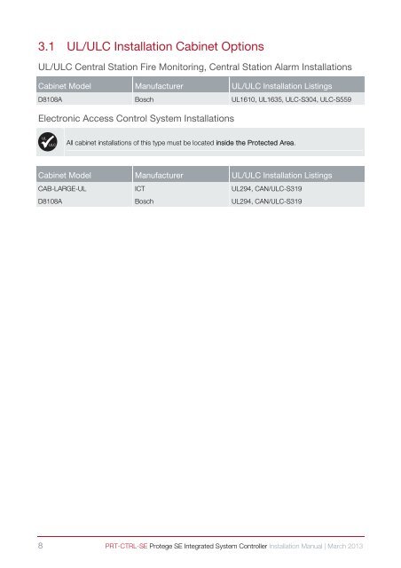
3.1 UL/ULC <strong>Installation</strong> Cabinet OptionsUL/ULC Central Station Fire Monitoring, Central Station Alarm <strong>Installation</strong>sCabinet Model Manufacturer UL/ULC <strong>Installation</strong> ListingsD8108A Bosch UL1610, UL1635, ULC-S304, ULC-S559Electronic Access Control System <strong>Installation</strong>sULULČAll cabinet installations of this type must be located inside the Protected Area.Cabinet Model Manufacturer UL/ULC <strong>Installation</strong> ListingsCAB-LARGE-UL <strong>ICT</strong> UL294, CAN/ULC-S319D8108A Bosch UL294, CAN/ULC-S3198 PRT-CTRL-SE Protege SE Integrated System Controller <strong>Installation</strong> <strong>Manual</strong> | March 2013
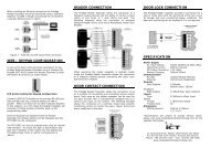
+-4 Connections4.1 Protege SE Integrated System Controller ConnectionGel CellBackupBattery(Min 7Ah)TamperSwitchCold waterearth pipeULC-LA ACIndicator*Inline5A 3AGfuseholder*The Protege ® SE Integrated SystemController shall be supplied by aTransformer: dedicated electrical power source rated16 to 16.5VACfor a minimum 10Amp load and have asecondary(via transformer) dedicated circuit breaker. Do not use aswitch controlled breaker or switchedelectrical point to supply electrical power.CAUTION: INCORRECTWIRING MAY RESULT INDAMAGE TO THE UNITProtege ® SE Integrated SystemController or module supplyingpower to networked devicesN+ N- NA NB+AUX- Z13 COM COMZ14 Z15 Z16AUX power from Moduleor external power supply8 Ohm 30WSiren or 1.1A(Maximum)8 Ohm 30WSiren or 1.1A(Maximum)LockPower Supply++ElectricLocking Device--Bracket1N4007DiodeRelay1K1K1K1K+1.1A (Maximum)ElectricLocking Device-+1.1A (Maximum)ElectricLocking Device-1k Resistors1k ResistorsN.C Zone Contact1K1KN.O Zone ContactN.C Zone Contact1K1K++T+ T- + - NO COM NCN.O Zone Contact--1N4007Diode1N4007DiodeDoor ContactREXBond SenseREN+AUX- Z1 COM COMZ2 Z3 Z4Value 1 Value 2 Monitored Status1K 1K Open, Close, Tamper, Short6K8 2K2 Open, Close, Tamper, Short10K 10K Open, Close, Tamper, Short2K2 2K2 Open, Close, Tamper, Short4K7 2K2 Open, Close, Tamper, Short4K7 4K7 Open, Close, Tamper, ShortB1+ B1- B2+ B2- P3 P4Nano Prox Reader(Optional Extra)N.CTamperShieldRedBlackGreenWhiteOrangeBrownBlueYellowTypical Zone Circuits*When installed with the power supply manufactured by Marcus (Model M4758CT), the Digital SecurityControls (DSC) Model ULC-LA power indicator light assembly (<strong>Installation</strong> Instruction No. 29001877 R0)must be installed within a conduit knockout of the <strong>ICT</strong> Model CAB-LARGE-UL or Bosch Model D8108Aenclosure in order to provide green AC power on indication. The Littelfuse Part No. 150322 fuseholderand Littelfuse Part No. 0312005 5A, 3AG fast-acting fuse must be installed in-line to the ModelsPRT-CTRL-SE, PRT-ZX16-PCB and PRT-RDI2-PCB.Servicing of theCR2032 batterymust be done by atrained technician.N.C Zone ContactValue 2 Value 1+AUX- Z1 COM COMZ2 Z3 Z4Switches 1 & 2 - Operating ModeSwitch Switch Function1 2 Power Up Boot ModeOFF OFF Normal Operation*ON OFF BOOT LoaderOFF ON BIOS UtilityON ON Reserved Do Not SetSwitch 3 - IP Address OverrideOFF Normal Operation*ON IP will be set to 192.168.111.222while this switch remains onSwitch 4 - Memory DefaultOFF Normal Operation*ON Factory Default*Default SettingZone OptionsProgrammable OutputsPGMs 3/4The PGM Outputs 3 (PGM3 CP001:03) and 4(PGM CP001:4) are Open Collector Outputs andswitch to OV. The PGM’s can be used to activaterelays, sounders and lights.LED1K5 OHMThe onboard readers ports use zone input 9 – 12 and13 - 16 as door contact, REX, bond sense and RENinputs respectively. Any of these inputs that are notused as general purpose zone inputs. Please referto the Protege ® SE Integrated System Controller<strong>Installation</strong> <strong>Manual</strong> Section 5.5 Programming theOnboard Reader.LEDStatusFaultWhiteBlueBlackRedCharge /TestAUX1 /AUX2AC5V ISOGreyBrownRedGreenLOCK1 /LOCK2BELL1 /BELL2NetworkRX / TXEthernetLinkEthernet100MbR1 / R2DataONLINEWiringSlow FlashFast FlashONOFFSlow FlashVaryingIntensityONOFFONOFFONOFFONOFFONOFF2 Flashes3 FlashesFast FlashOFFONOFFFast FlashONOFFSlow FlashFast FlashONOFFModem InterfaceSurge ProtectorEarth Ground Link connectionprovided via metallic enclosureN+ N- NA NBLED IndicatorsDescriptionProtege SystemController operating normallyController is in BIOS modeController is in BIOS modeController operating normallyupdateNext moduleson networkRJ31XBattery is being charged, indicator’s intensityshows charging currentBattery test in progressBattery is fully charged (if AC Indicator is ON)Auxiliary supply is normalAuxiliary supply is in over current protectionValid AC input providedAC is disconnected or has failedValid power supply providedPower supply disconnected or is not poweredproperlyLOCK/BELL is ONLOCK/BELL is OFFL-COMHGLN-D1DTLOCK/BELL is ON, the circuit is in over currentprotectionLOCK/BELL is OFF, the circuit to the lockingdevice is cut, damaged, or tamperedData packet transmitted/receivedNo data packet transmitted/receivedLive Ethernet connection detectedNo Ethernet connection detectedEthernet packet transmitted/receivedEthernet connection operates at 100MbEthernet connection does not operate at100MbData received in valid formatData received in invalid formatOnboard modem off hookOnboard modem not activeEARTH GND WIRING: Minimum 14AWG solid copper wire.ZONE WIRING: maximum distance of 300m (1000ft) from the Protege ®SE Integrated System Controller when using 22 AWG.AUX WIRING: Min 22AWG Max 16AWG. (Depends on length and Currentconsumption). For wire/cable size, a maximum of 5% voltage drop at theterminals of the powered device has to be observed.ETHERNET WIRING: CAT5e / CAT6 max 100m (330 ft)MODULE NETWORK WIRING: Recommended Belden 9842 or equivalent.(24AWG twisted pair with characteristic impedance of 120ohm or CAT5e /CAT6 are also supported for Data Transmission when using ground in thesame cable. Do not use extra wires to power devices.) max 900m (3000ft).PRT-CTRL-SE Protege SE Integrated System Controller <strong>Installation</strong> <strong>Manual</strong> | March 2013 9