Installation Manual - ICT
Installation Manual - ICT
Installation Manual - ICT
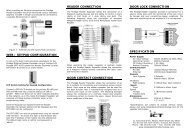
- No tags were found...

You also want an ePaper? Increase the reach of your titles
YUMPU automatically turns print PDFs into web optimized ePapers that Google loves.
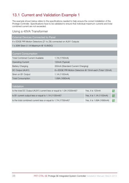
13.1 Current and Validation Example 1The example shown below refers to the specifications needed to help ensure the correct installation of theProtege Controller. Specifications have to be validated to ensure that individual maximum currents and totalcombined current are not exceeded.Using a 40VA TransformerExternal Devices Connected to Panel8 x EDGE PIR Motion Detectors (Z1 to Z8) connected on AUX1 Outputs1 x 30W Siren (1.1A Maximum @ 13.8VDC)Current ConsumptionTotal Combined Current AvailableOperating CurrentBattery ChargingDC Output (AUX1)Siren on B1 OutputTotal Consumption1.7A (1700mA)120mA (Typical)350mA (Standard Current Charging)8 x EDGE PIR Motion Detectors @ 15mA each (Total 120mA)1.1A (1100mA)1.69A (1690mA)ValidationIs the total DC Output (AUX1) current less or equal to 1.0A (1000mA)? Yes, it is 120mA Is B1 current output less or equal to 1.1A (1100mA)? Yes, it is 1.1A (1100mA) Is the total combined current less or equal to 1.7A (1700mA)? Yes, it is 1.69A (1690mA) 38 PRT-CTRL-SE Protege SE Integrated System Controller <strong>Installation</strong> <strong>Manual</strong> | March 2013