Installation Manual - ICT
Installation Manual - ICT
Installation Manual - ICT
- No tags were found...

You also want an ePaper? Increase the reach of your titles
YUMPU automatically turns print PDFs into web optimized ePapers that Google loves.
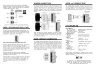
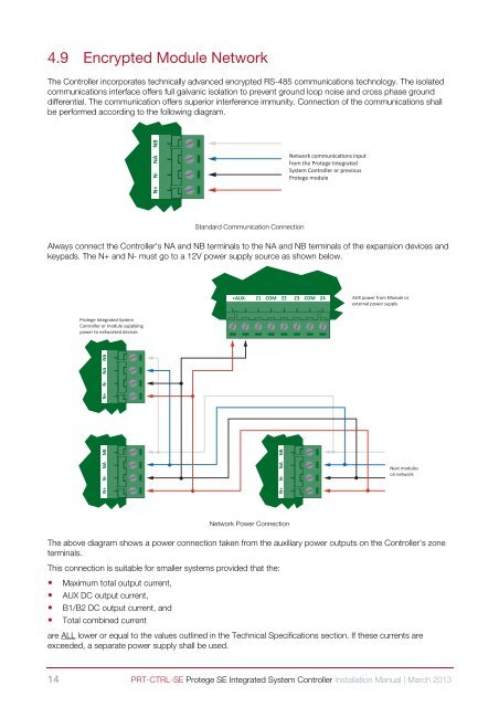
4.9 Encrypted Module NetworkThe Controller incorporates technically advanced encrypted RS-485 communications technology. The isolatedcommunications interface offers full galvanic isolation to prevent ground loop noise and cross phase grounddifferential. The communication offers superior interference immunity. Connection of the communications shallbe performed according to the following diagram.N+ N- NA NBNetwork communicaons inputfrom the Protege IntegratedSystem Controller or previousProtege moduleStandard Communication ConnectionAlways connect the Controller's NA and NB terminals to the NA and NB terminals of the expansion devices andkeypads. The N+ and N- must go to a 12V power supply source as shown below.+AUX- Z1 COM Z2 Z3 COM Z4AUX power from Module orexternal power supplyProtege Integrated SystemController or module supplyingpower to networked devicesN+ N- NA NBN+ N- NA NBN+ N- NA NBNext moduleson networkNetwork Power ConnectionThe above diagram shows a power connection taken from the auxiliary power outputs on the Controller's zoneterminals.This connection is suitable for smaller systems provided that the:• Maximum total output current,• AUX DC output current,• B1/B2 DC output current, and• Total combined currentare ALL lower or equal to the values outlined in the Technical Specifications section. If these currents areexceeded, a separate power supply shall be used.14 PRT-CTRL-SE Protege SE Integrated System Controller <strong>Installation</strong> <strong>Manual</strong> | March 2013