Installation Manual - ICT
Installation Manual - ICT
Installation Manual - ICT
- No tags were found...

You also want an ePaper? Increase the reach of your titles
YUMPU automatically turns print PDFs into web optimized ePapers that Google loves.
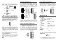
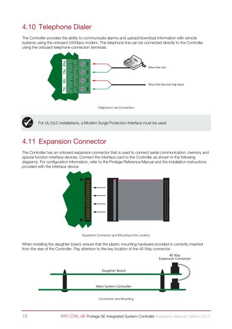
4.10 Telephone DialerThe Controller provides the ability to communicate alarms and upload/download information with remotesystems using the onboard 2400bps modem. The telephone line can be connected directly to the Controllerusing the onboard telephone connection terminals.T1i R1i T1o R1oTelco line outTelco line p and ring inputTelephone Line ConnectionULULČFor UL/ULC installations, a Modem Surge Protection Interface must be used.4.11 Expansion ConnectorThe Controller has an onboard expansion connector that is used to connect serial communication, memory andspecial function interface devices. Connect the interface card to the Controller as shown in the followingdiagrams. For configuration information, refer to the Protege Reference <strong>Manual</strong> and the installation instructionsprovided with the interface device.Expansion Connector and Mounting Hole LocationWhen installing the daughter board, ensure that the plastic mounting hardware provided is correctly insertedfrom the rear of the Controller. Pay attention to the key location of the 40 Way connector.40 WayExpansion ConnectorDaughter BoardMain System ControllerConnection and Mounting16 PRT-CTRL-SE Protege SE Integrated System Controller <strong>Installation</strong> <strong>Manual</strong> | March 2013