K-Series (2-7.5 KGA) Service Manual - Allied Commercial
K-Series (2-7.5 KGA) Service Manual - Allied Commercial
K-Series (2-7.5 KGA) Service Manual - Allied Commercial
- No tags were found...

Create successful ePaper yourself
Turn your PDF publications into a flip-book with our unique Google optimized e-Paper software.
OPTIONS / ACCESSORIESItemCatalogNo.024 030 036 048 060 072 090COOLING SYSTEMCondensate Drain Trap PVC - C1TRAP20AD2 76W26 X X X X X X XCopper - C1TRAP10AD2 76W27 X X X X X X XCompressor Crankcase Heater 208/230V-1 or 3 ph - K1CCHT02A-1P 39W04 X X X208/230V-1 or 3 ph - T1CCHT01AN1P 95M07 X X460V-3ph - K1CCHT012A-1G 39W05 X460V-3ph - T1CCHT01AN1G 95M08 X X575V-3ph - K1CCHT02A-1J 39W06 X575V-3ph - T1CCHT01AN1J 95M09 X XDrain Pan Overflow Switch K1SNSR71AB1- 74W42 X X X X X X XLow Ambient Kit K1SNSR33AN1 41W33 X X X X X X XEfficiency Standard O O O O O O ORefrigerant Type R-410A O O O O O O OHEATING SYSTEMBottom Gas Piping Kit T1GPKT01AN1 19W50 X X X X X X XLow Temperature Vestibule208/230V-1 or 3 ph - T1CWKT01AN1Y 19W53 X X X X X X XHeater460V-3ph - T1CWKT01AN1G 19W54 X X X X X575V-3ph - T1CWKT01AN1J 19W62 X X X X XCombustion Air IntakeT1EXTN10AN1 19W51 X X X X X X XExtensionsGas Heat Input Standard One-Stage - 65 kBtuh input O O O O O OMedium One-Stage - 105 kBtuh input O O O O OHigh Two-Stage - 105/150 kBtuh input O O O OHigh One-Stage - 150 kBtuh input O O O OLPG/PropaneFor one-stage models - C1PROP10AP1 53W69 X X X X X X XConversion KitsFor two-stage models - C1PROP20AP1 53W70 X X X X XStainless Steel Heat Exchanger O O O O O O OVertical Vent Extension C1EXTN20FF1 31W62 X X X X X X XBlower - SUPPLY AIRMotors Direct Drive - 0.25 hp O ODirect Drive - 0.5 hp O ODirect Drive - 0.75 hpOBelt Drive - 1 hp Standard EfficiencyOBelt Drive - 1.5 hp Standard Efficiency O O O O1Belt Drive - 2 hp Standard Efficiency O O O O OBelt Drive - 3 hp Standard EfficiencyODrive KitsKit A01 - T1DRKT001-1 - 673-1010 rpm Factory OSee Blower Data TablesKit A02 - T1DRKT002-1 - 745-1117 rpm Factory Ofor selectionKit A03 - T1DRKT003-1 - 833-1250 rpm Factory OKit A04 - T1DRKT004-1 - 968-1340 rpm Factory OKit A05 - T1DRKT005-1 - 897-1346 rpm Factory OKit A06 - T1DRKT006-1 - 1071-1429 rpm Factory OKit A07 - T1DRKT007-1 - 1212-1548 rpm Factory OKit A08 - T1DRKT008-1 - 1193-1591 rpm Factory OKit AA01 - T1DRKT001AP1 - 522-784 rpm Factory OKit AA02 - T1DRKT002AP1 - 632-875 rpm Factory OKit AA03 - T1DRKT003AP1 - 798-1105 rpm Factory OKit AA04 - T1DRKT004AP1 - 921-1228 rpm Factory ONOTE - The catalog and model numbers that appear here are for ordering field installed accessories only.OX - Field Installed or Configure to Order (factory installed)O - Configure to Order (Factory Installed)X - Field Installed.12 hp blower motor is not available for 208/230V-1ph applications.Page 2
OPTIONS / ACCESSORIESItemCatalogNo.024 030 036 048 060 072 090CABINETCoil Guards T1GARD20A-1 17W87 X X X X XT1GARD20N-1 17W88 XK1GARD20AP1 53W21 XCorrosion Protection O O O O O O OHail Guards T1GARD10A-1 17W89 X X X X XT1GARD10N-1 17W90 XK1GARD10AP1 53W22 XHinged Access Panels O O O O O O OCONTROLSSmoke Detector - Supply or ReturnC1SNSR44AP1 53W78 X X X X X X X(Power board and one sensor)Smoke Detector - Supply and ReturnC1SNSR43AP1 53W79 X X X X X X X(Power board and two sensors)ELECTRICALVoltage208/230V - 1 phase O O O O O60 hz208/230V - 3 phase O O O O O460V - 3 phase O O O O O575V - 3 phase O O O O ODisconnect See Electric Data Tables for usage OX OX OX OX OX OX OXGFI <strong>Service</strong> Outlets LTAGFIK10/15 74M70 OX OX OX OX OX OX OXECONOMIZEREconomizerEconomizer, Single Enthalpy ControlT1ECON30A-1 36W96 OX OX OX OX OXIncludes Outdoor Air Hood andBarometric Relief Dampers with HoodT1ECON30N-1 36W97 OX OXHorizontal Economizer Conversion Kit T1HECK00AN1 17W45 X X X X X X XEconomizer ControlsDifferential Enthalpy Sensor T1SNSR60AN1 17W71 X X X X X X XSingle Temperature Control TASEK10/15 76M37 X X X X X X XDifferential Temperature Control Order 2 - TASEK10/15 76M37 X X X X X X XOUTDOOR AIROutdoor Air DampersDamper Section - <strong>Manual</strong>, IncludesT1DAMP11A-1 16W88 X X X X XOutdoor Air HoodT1DAMP11N-1 16W91 X XDamper Motorized Kit - Order <strong>Manual</strong>T1DAMP21AN1 16W92 X X X X X X XOutdoor Air Damper SeparatelyPower Exhaust FANStandard Static 208/230V-1 or 3 ph - T1PWRE10A-1P 17W39 X X X460V-3ph - T1PWRE10A-1G 17W40 X X X575V-3ph - T1PWRE10A-1J 17W41 X X X208/230V-1 or 3 ph - T1PWRE10N-1P 17W42 X X460V-3ph - T1PWRE10N-1G 17W43 X X575V-3ph - T1PWRE10N-1J 17W44 X XNOTE - The catalog and model numbers that appear here are for ordering field installed accessories only.OX - Field Installed or Configure to Order (factory installed)O - Configure to Order (Factory Installed)X - Field Installed.Page 3
OPTIONS / ACCESSORIESItemCatalog 024 030 036 048 060 072 090No.Indoor Air QualityIndoor Air Quality (Co 2) SensorsSensor - Wall-mount, off-white plastic cover with LCDC0SNSR50AE1L 77N39 X X X X X X XdisplaySensor - Wall-mount, black plastic case, no display, ratedC0SNSR53AE1L 87N54 X X X X X X Xfor plenum mountingCO 2Sensor Duct Mounting Kit - for downflow applications C0MISC19AE1- 85L43 X X X X X X XAspiration Box - for duct mounting non-plenum rated CO2C0MISC16AE1- 90N43 X X X X X X Xsensor (77N39)UVC Germicidal Lamps2Healthy Climate ® UVC Light Kit (208/230v-1ph) E1UVCL10AN1- 50W90 X X X X X X XCEILING DIFFUSERSStep-Down - Order one RTD9-65-R 27G87 X X X X XRTD11-95 29G04 X X(Canada Only) RTD11-95S 13K61 X XFlush - Order one FD9-65-R 27G86 X X X X XFD11-95 29G08 X X(Canada Only) FD11-95S 13K56 X XTransitions (Supply and Return) - Order one T1TRAN10AN1 17W53 X X X X XT1TRAN20N-1 17W54 X XROOF CURBS - downFlowCliplock8 in. height T1CURB23AN1 16W93 X X X X X X 1 XK1CURB23AP1 52W20 X14 in. height T1CURB20AN1 16W94 X X X X X X 1 XK1CURB20AP1 52W21 X18 in. height T1CURB21AN1 16W95 X X X X X X 1 XK1CURB21AP1 52W22 X24 in. height T1CURB22AN1 16W96 X X X X X X 1 XK1CURB22AP1 52W23 XHinged8 in. height T1CURB30AN1 17W46 X X X X X X 1 XK1CURB30AP1 52W17 X18 in. height T1CURB32AN1 17W47 X X X X X X 1 XK1CURB32AP1 52W18 X24 in. height T1CURB33AN1 17W48 X X X X X X 1 XK1CURB33AP1 52W19 XStandard14 in. height T1CURB10AN1 13W27 X X X X X X 1 XK1CURB10AP1 52W24 XAdjustable Pitched Curb14 in. height C1CURB55AT1 43W27 X X X X X X 2 XNOTE - The catalog and model numbers that appear here are for ordering field installed accessories only.OX - Field Installed or Configure to Order (factory installed)O - Configure to Order (Factory Installed)X - Field Installed.1090 models will fit smaller roof curbs with overhang. See dimension drawing.2Lamps operate on 110-230V single-phase power supply. Step-down transformer may be ordered separately for 460V and 575V units. Alternately, 110V power supplymay be used to directly power the UVC ballast(s).Page 4
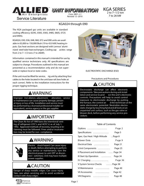
SPECIFICATIONS - DIRECT DRIVE BLOWERGeneral Data Nominal Tonnage 2 Ton 2.5 TonModel No. <strong>KGA</strong>024S4D <strong>KGA</strong>030S4D2 - 2.5 TONEfficiency Type Standard StandardCoolingGross Cooling Capacity - Btuh 24,400 29,800Performance1Net Cooling Capacity - Btuh 23,600 28,800AHRI Rated Air Flow - cfm 840 10002Sound Rating Number (dB) 75 75Total Unit Power - kW 2.1 2.61SEER (Btuh/Watt) 13 131EER (Btuh/Watt) 11.4 11.2Refrigerant Type R-410A R-410ACharge Furnished 7 lbs. 0 oz. 7 lbs. 12 oz.Gas Heating Options - See Page 12 Standard (1 Stage) Standard (1 Stage)Compressor Type (one per unit) Scroll ScrollOutdoor Coil Net face area - sq. ft. 15.6 15.6Tube diameter - in. 3/8 3/8Number of rows 1 1Fins per inch 20 20OutdoorMotor HP 1/4 1/4Coil FanMotor rpm 825 825Total motor watts 250 250Diameter - in. / No. of blades 24 - 3 24 - 3Total air volume - cfm 3700 3700Indoor Coil Net face area - sq. ft. 7.8 7.8Tube diameter - in. 3/8 3/8Number of rows 3 3Fins per inch 14 14Drain Connection (no. and size) - in. (1) 3/4 npt (1) 3/4 nptExpansion device type Balanced Port Thermostatic Expansion Valve, removeable power headIndoor Blower Nominal Motor HP .25 .25Wheel nominal diameter x width - in. 10 x 10 10 x 10Filters Type DisposableNumber and size - in. (4) 16 x 20 x 2Electrical Characteristics - 60 Hz 208/230V1 phase208/230V1 phaseNOTE - Net capacity includes evaporator blower motor heat deduction. Gross capacity does not include evaporator blower motor heat deduction.1Certified in accordance with the USE certification program, which is based on AHRI Standard 210/240; 95°F outdoor air temperature and 80°F db/67°F wb enteringevaporator air; minimum external duct static pressure.2Sound Rating Number rated in accordance with test conditions included in AHRI Standard 270.Page 5
SPECIFICATIONS - DIRECT DRIVE BLOWER3 - 5 TONGeneral Data Nominal Tonnage 3 Ton 4 Ton 5 TonModel No. <strong>KGA</strong>036S4D <strong>KGA</strong>048S4D <strong>KGA</strong>060S4DEfficiency Type Standard Standard StandardCooling Gross Cooling Capacity - Btuh 37,500 50,000 61,800Performance 1Net Cooling Capacity - Btuh 36,000 48,000 59,000AHRI Rated Air Flow - cfm 1200 1600 18002Sound Rating Number (dB) 75 75 82Total Unit Power - kW 3.4 4.4 5.31SEER (Btuh/Watt) 13 13 131EER (Btuh/Watt) 10.7 11 11.2Refrigerant Type R-410A R-410A R-410ACharge Furnished 8 lbs. 5 oz. 8 lbs. 10 oz. 11 lbs. 0 oz.Gas Heating Options - See page 8Standard or Medium(1 Stage)Standard, Medium (1 Stage)or High (1 or 2 Stage)Compressor Type (one per unit) Scroll Scroll ScrollOutdoor Coil Net face area - sq. ft. 15.6 15.6 15.6Tube diameter - in. 3/8 3/8 3/8Number of rows 1 1.5 2Fins per inch 20 20 20OutdoorMotor HP 1/4 1/4 1/3Coil FanMotor rpm 825 825 1075Total motor watts 250 250 370Diameter - in. / No. of blades 24 - 3 24 - 3 24 - 3Total air volume - cfm 3700 3500 4300Indoor Coil Net face area - sq. ft. 7.8 7.8 7.8Tube diameter - in. 3/8 3/8 3/8Number of rows 3 3 4Fins per inch 14 14 14Drain Connection (no. and size) - in. (1) 3/4 npt (1) 3/4 npt (1) 3/4 nptExpansion device type Balanced Port Thermostatic Expansion Valve, removeable power headIndoorNominal Motor HP .5 .5 .75BlowerWheel nominal diameter x width - in. 10 x 10 10 x 10 11 x 10Filters Type DisposableNumber and size - in. (4) 16 x 20 x 2Electrical Characteristics - 60 Hz 208/230V1 phase208/230V,460V & 575V3 phase208/230V1 phase208/230V,460V & 575V3 phase208/230V1 phase208/230V,460V & 575V3 phaseNOTE - Net capacity includes evaporator blower motor heat deduction. Gross capacity does not include evaporator blower motor heat deduction.1Certified in accordance with the USE certification program, which is based on AHRI Standard 210/240; 95°F outdoor air temperature and 80°F db/67°F wb enteringevaporator air; minimum external duct static pressure.2Sound Rating Number rated in accordance with test conditions included in AHRI Standard 270.Page 6
SPECIFICATIONS - BELT DRIVE BLOWER3 - <strong>7.5</strong> TONGeneral Data Nominal Tonnage 3 Ton 4 Ton 5 Ton 6 Ton <strong>7.5</strong> TonModel No. <strong>KGA</strong>036S4B <strong>KGA</strong>048S4B <strong>KGA</strong>060S4B <strong>KGA</strong>072S4B <strong>KGA</strong>090S4BEfficiency Type Standard Standard Standard Standard StandardCooling Gross Cooling Capacity - Btuh 37,500 50,000 61,800 72,800 92,000Performance Net Cooling Capacity - Btuh136,000148,000159,000270,000290,000AHRI Rated Air Flow - cfm 1200 1600 1800 2100 25004Sound Rating Number (dB) 75 75 82 82 79Total Unit Power - kW 3.4 4.4 5.3 6.3 8.2SEER (Btuh/Watt) 13.0 13.0 13.0 - - - - - -3IEER (Btuh/Watt) - - - - - - - - - 11.2 11.2EER (Btuh/Watt)110.7111111.2211.0211.0Refrigerant Type R-410A R-410A R-410A R-410A R-410ACharge Furnished 8 lbs. 5 oz. 8 lbs. 10 oz. 11 lbs. 0 oz. 14 lbs. 12 oz. 17 lbs. 0 oz.Gas Heating Options - See page 8MediumStandard orStandard, Medium (1 Stage)(1 Stage)Medium(1 Stage)or High (1 or 2 Stage)or High(1 or 2 Stage)Compressor Type (one per unit) Scroll Scroll Scroll Scroll ScrollOutdoor Coil Net face area - sq. ft. 15.6 15.6 15.6 19.3 28.0Tube diameter - in. 3/8 3/8 3/8 3/8 3/8Number of rows 1 1.5 2 2 2Fins / inch 20 20 20 20 20OutdoorCoil FanMotor HP 1/4 1/4 1/3 1/3 1/3Motor rpm 825 825 1075 1075 1075Total motor watts 250 250 370 405 350Diameter - in. / No. of blades 24 - 3 24 - 3 24 - 3 24 - 3 24 - 3Total air volume - cfm 3700 3500 4300 4800 4900Indoor Coil Net face area - sq. ft. 7.8 7.8 7.8 9.7 9.7Tube diameter - in. 3/8 3/8 3/8 3/8 3/8Number of rows 3 3 4 4 4Fins per inch 14 14 14 14 14Drain Connection (no.and size) - in. (1) 3/4 NPT (1) 3/4 NPT (1) 3/4 NPT (1) 3/4 NPT (1) 3/4 NPT5IndoorBlower & DriveSelectionExpansion device type Balanced Port Thermostatic Expansion Valve, removeable power headNominal Motor HP 1.5 hp, 6 2 hp 1.5 hp, 6 2 hp 1.5 hp, 6 2 hp 1.5 hp, 2 hp 1 hpMaximum Usable Motor HP 1.7 hp, 2.3 hp 1.7 hp, 2.3 hp 1.7 hp, 2.3 hp 1.7 hp, 2.3 hp 1.15 hpAvailable Drive KitsA01A02A03A04673 - 1010 rpm 745 - 1117 rpm 833 - 1250 rpm 968 - 1340 rpmA05A06A07A08897 - 1346 rpm 1071 - 1429 rpm 1212 - 1548 rpm 1193 - 1591 rpmPage 7AA01522 - 784 rpmNominal Motor HP - - - - - - - - - - - - 2 hpMaximum Usable Motor HP - - - - - - - - - - - - 2.3 hpAvailable Drive Kits - - - - - - - - - - - - AA02632 - 875 rpmAA03798 - 1105 rpm- - - - - - - - - - - - 3 hp- - - - - - - - - - - - 3.45 hp- - - - - - - - - - - -AA04921 - 1228 rpmWheel nominal diameter x width - in. 10 x 10 10 x 10 10 x 10 10 x 10 15 x 9Filters Type Disposable DisposableNumber and size - in. (4) 16 x 20 x 2 (4) 20 x 20 x 2Electrical Characteristics - 60 Hz 208/230V1 phase208/230V,460V & 575V3 phase208/230V,1 phase208/230V460V & 575V3 phase208/230V1 phase208/230V, 460V& 575V3 phase208/230V,460V & 575V3 phase208/230V,460V & 575V3 phaseNOTE - Net capacity includes evaporator blower motor heat deduction. Gross capacity does not include evaporator blower motor heat deduction.1Certified in accordance with the USE certification program, which is based on AHRI Standard 210/240; 95°F outdoor air temperature and 80°F db/67°F wb enteringevaporator air; minimum external duct static pressure.2Certified in accordance with the ULE certification program, which is based on AHRI Standard 340/360; 95°F outdoor air temperature and 80°F db/67°F wb enteringevaporator air; minimum external duct static pressure.3Integrated Energy Efficiency Ratio certified and tested according to AHRI Standard 340/360.4Sound Rating Number rated in accordance with test conditions included in AHRI Standard 270.5Using total air volume and system static pressure requirements determine from blower performance tables rpm and motor hp required. Maximum usable hp of motorsfurnished are shown. In Canada, nominal motor hp is also maximum usable motor hp output. If motors of comparable hp are used, be sure to keep within the servicefactor limitations outlined on the motor nameplate.62 hp blower motor is not available for 208/230V-1ph applications.
SPECIFICATIONS - GAS HEATModel No.Heat Input Type<strong>KGA</strong>024,<strong>KGA</strong>030Standard(1 Stage)<strong>KGA</strong>036,<strong>KGA</strong>048,<strong>KGA</strong>060,<strong>KGA</strong>072Standard(1 Stage)<strong>KGA</strong>036,<strong>KGA</strong>048,<strong>KGA</strong>060,<strong>KGA</strong>072,<strong>KGA</strong>090Medium(1 Stage)<strong>KGA</strong>048, <strong>KGA</strong>060,<strong>KGA</strong>072, <strong>KGA</strong>090High(1 Stage)High(2 Stage)Input - Btuh First Stage 65,000 65,000 105,000 150,000 105,000Second Stage - - - - - - - - - - - - 150,000Output - Btuh First Stage 52,000 52,000 84000 120,000 85,500Second Stage - - - - - - - - - - - - 120,000Temperature Rise Range 35 - 65°F 20 - 50°F 30 - 75°F 40 - 85°F 40 - 85°F1AFUE 80% 80% 80% 80% 80%Thermal Efficiency 80% 80% 80% 80% 81.5%/80%Gas Supply Connections1/2 in. NPTRec. Gas Supply Pressure - Natural / LPG7 in. w.g. / 11 in. w.g.1Annual Fuel Utilization Efficiency based on U.S. DOE test procedures and FTC labeling regulations.HIGH ALTITUDE DERATENOTE - Units may be installed at altitudes up to 2000 ft. abovesea level without any modifications.At altitudes above 2000 ft. units must be derated tomatch information in the table shown.At altitudes above 4500 ft. unit must be derated 2% foreach 1000 ft. above sea level.NOTE - This is the only permissible derate for these units.Heat InputTypeStandard(1 stage)Medium(1 stage)High(1 stage)High(2 stage)AltitudeFeetGas Manifold Pressurein. w.g.NaturalGasLPG/PropaneInput Rate(Btuh)2001 - 4500 3.0 9.0 60,0002001 - 4500 3.0 9.0 97,0002001 - 4500 3.0 9.0 138,0002001 - 4500 3.0/1.7 9.0/5.1 138,000/105,000Page 8
BLOWER DATA - DIRECT DRIVE2 - 2.5 TONBLOWER TABLE INCLUDES RESISTANCE FOR BASE UNIT ONLY WITH DRY INDOOR COIL AND AIR FILTERS IN PLACE.FOR ALL UNITS ADD:1 - Any factory installed options air resistance (larger gas heat section, economizer, wet coil, etc.) See page 19.2 - Any field installed accessories air resistance (duct resistance, diffuser, etc.) See page 19.External StaticAir Volume (cfm) at Various Blower SpeedsPressure (in. w.g.)208 VOLTS 230 VOLTSHigh Medium Low High Medium Low2 and 2.5 Ton Standard Efficiency (Downflow) <strong>KGA</strong>024S and <strong>KGA</strong>030S0.0 1211 949 852 1365 1097 9160.1 1251 946 826 1422 1099 9080.2 1241 952 794 1419 1112 8930.3 1234 915 749 1419 1074 8610.4 1213 880 702 1402 1038 8240.5 1178 846 661 1366 1003 7950.6 1118 790 585 1302 942 7200.7 1054 751 518 1231 900 6550.8 964 675 460 1130 815 6000.9 882 626 368 1037 762 5011.0 729 494 286 859 606 4122 and 2.5 Ton Standard Efficiency (Horizontal) <strong>KGA</strong>024S and <strong>KGA</strong>030S0.0 1163 930 815 1312 1075 8750.1 1173 912 783 1333 1060 8610.2 1169 888 746 1337 1037 8390.3 1152 858 704 1325 1007 8090.4 1122 822 657 1297 969 7720.5 1079 779 606 1252 923 7280.6 1023 730 549 1191 870 6760.7 953 674 488 1114 808 6170.8 871 613 422 1020 739 5500.9 775 545 350 911 662 4761.0 666 470 274 785 578 395Page 9
BLOWER DATA - DIRECT DRIVE3 - 4 TONBLOWER TABLE INCLUDES RESISTANCE FOR BASE UNIT ONLY WITH DRY INDOOR COIL AND AIR FILTERS IN PLACE.FOR ALL UNITS ADD:1 - Any factory installed options air resistance (larger gas heat section, economizer, wet coil, etc.) See page 19.2 - Any field installed accessories air resistance (duct resistance, diffuser, etc.) See page 19.External StaticAir Volume (cfm) at Various Blower SpeedsPressure (in. w.g.)208 VOLTS 230 VOLTS 460/575 VOLTSHigh Medium Low High Medium Low High Medium Low3 and 4 Ton Standard Efficiency (Downflow) <strong>KGA</strong>036S and <strong>KGA</strong>048S0.0 1873 1561 1123 2094 1783 1321 2064 1727 12160.1 1993 1601 1148 2168 1797 1338 2105 1744 12290.2 1913 1601 1137 2098 1803 1308 2050 1694 11980.3 1858 1527 1078 2036 1725 1261 1987 1638 11670.4 1801 1496 1046 1973 1679 1219 1905 1598 11480.5 1763 1467 987 1910 1647 1177 1862 1559 11080.6 1709 1414 897 1830 1560 1080 1781 1509 10570.7 1617 1368 806 1727 1519 986 1698 1449 9820.8 1472 1269 730 1604 1419 918 1614 1389 9200.9 1359 1162 487 1478 1363 706 1488 1346 7921.0 961 922 370 1093 1083 590 1167 1099 7033 and 4 Ton Standard Efficiency (Horizontal) <strong>KGA</strong>036S and <strong>KGA</strong>048S0.0 1799 1530 1073 2012 1747 1263 2015 1756 12510.1 1868 1544 1088 2032 1733 1268 2071 1760 12790.2 1802 1494 1068 1976 1682 1228 2014 1700 12260.3 1735 1432 1014 1900 1618 1185 1937 1634 11870.4 1666 1397 980 1825 1568 1142 1878 1597 11740.5 1615 1350 904 1750 1516 1078 1801 1558 11240.6 1564 1305 842 1675 1440 1014 1743 1479 10600.7 1462 1228 758 1562 1364 928 1664 1415 9820.8 1330 1151 670 1449 1287 842 1512 1335 8650.9 1194 1011 464 1298 1185 671 1393 1297 7331.0 878 878 355 998 1032 565 1060 1063 618Page 10
BLOWER DATA - DIRECT DRIVEBLOWER TABLE INCLUDES RESISTANCE FOR BASE UNIT ONLY WITH DRY INDOOR COIL AND AIR FILTERS IN PLACE.FOR ALL UNITS ADD:1 - Any factory installed options air resistance (larger gas heat section, economizer, wet coil, etc.) See page 19.2 - Any field installed accessories air resistance (duct resistance, diffuser, etc.) See page 19.5 TONExternal StaticAir Volume (cfm) at Various Blower SpeedsPressure (in. w.g.)208 VOLTS 230 VOLTS 460/575 VOLTSHigh Low High Low High Low5 Ton Standard Efficiency (Downflow) <strong>KGA</strong>060S0.0 2200 1649 2411 1957 2241 17550.1 2256 1669 2417 2002 2221 17420.2 2202 1739 2396 1985 2193 17470.3 2170 1705 2328 1972 2144 17250.4 2158 1689 2293 1959 2104 16950.5 2130 1676 2279 1930 2086 16780.6 2056 1662 2158 1900 2008 16520.7 2032 1657 2089 1857 1975 16100.8 1963 1591 2077 1796 1941 15860.9 1887 1597 1876 1746 1855 15551.0 1695 1400 1746 1601 1778 14865 Ton Standard Efficiency (Horizontal) <strong>KGA</strong>060S0.0 2114 1615 2305 1880 2308 18900.1 2115 1610 2290 1876 2334 19060.2 2074 1622 2249 1870 2292 18900.3 2025 1599 2188 1841 2230 18590.4 1996 1577 2148 1812 2210 18460.5 1952 1542 2087 1768 2148 18170.6 1882 1534 2026 1739 2108 17860.7 1838 1488 1966 1680 2094 17430.8 1773 1443 1905 1622 1988 16820.9 1657 1389 1784 1534 1915 16791.0 1548 1335 1672 1462 1853 1506Page 11
BLOWER DATA - BELT DRIVE - <strong>KGA</strong>048BLOWER TABLE INCLUDES RESISTANCE FOR BASE UNIT ONLY WITH DRY INDOOR COIL AND AIR FILTERS IN PLACE.FOR ALL UNITS ADD:1 - Any factory installed options air resistance (heat section, economizer, wet coil, etc.).2 - Any field installed accessories air resistance (duct resistance, diffuser, etc.).See page 19for blower motors and drives and wet coil and options/accessory air resistance data.DOWNFLOWAirVolumecfmExternal Static - in. w.g.0.10 0.20 0.30 0.40 0.50 0.60 0.70 0.80RPM BHP RPM BHP RPM BHP RPM BHP RPM BHP RPM BHP RPM BHP RPM BHPField FurnishedKit A021200 574 0.20 644 0.24 713 0.28 784 0.31 850 0.33 906 0.36 953 0.39 998 0.421300 608 0.24 677 0.28 744 0.31 813 0.34 874 0.37 925 0.40 969 0.43 1014 0.461400 645 0.28 712 0.31 778 0.35 842 0.38 898 0.41 944 0.44 986 0.48 1030 0.511500 684 0.31 749 0.35 811 0.38 871 0.42 921 0.45 963 0.49 1004 0.53 1048 0.561600 723 0.35 785 0.39 844 0.43 898 0.46 943 0.50 983 0.54 1024 0.58 1067 0.611700 761 0.40 819 0.44 875 0.48 924 0.52 965 0.56 1004 0.60 1045 0.63 1089 0.661800 798 0.45 853 0.49 905 0.54 950 0.58 990 0.62 1028 0.66 1069 0.69 1112 0.721900 834 0.51 885 0.55 934 0.60 977 0.64 1015 0.68 1054 0.72 1095 0.75 1137 0.792000 869 0.57 917 0.62 962 0.67 1004 0.71 1042 0.75 1081 0.78 1121 0.82 1162 0.86AirVolumecfmExternal Static - in. w.g.0.90 1.00 1.10 1.20 1.30 1.40 1.50 1.60RPM BHP RPM BHP RPM BHP RPM BHP RPM BHP RPM BHP RPM BHP RPM BHPKit A02Kit A061200 1043 0.44 1090 0.47 1135 0.50 1179 0.53 1220 0.57 1259 0.60 1297 0.64 1333 0.671300 1058 0.49 1104 0.51 1148 0.55 1190 0.58 1231 0.62 1269 0.65 1306 0.69 1342 0.721400 1074 0.53 1119 0.56 1162 0.59 1203 0.63 1242 0.67 1280 0.71 1317 0.74 1352 0.781500 1092 0.58 1136 0.61 1177 0.65 1217 0.69 1255 0.73 1292 0.76 1328 0.80 1364 0.841600 1112 0.63 1154 0.67 1193 0.71 1232 0.75 1269 0.79 1306 0.83 1341 0.87 1377 0.911700 1132 0.69 1173 0.73 1211 0.77 1248 0.81 1285 0.86 1321 0.90 1356 0.94 1391 0.981800 1154 0.76 1194 0.80 1230 0.85 1266 0.89 1302 0.93 1338 0.98 1373 1.02 1408 1.061900 1178 0.83 1215 0.88 1250 0.93 1286 0.98 1321 1.02 1356 1.06 1391 1.10 1426 1.142000 1201 0.91 1237 0.97 1271 1.02 1307 1.07 1342 1.11 1376 1.15 1411 1.19 1446 1.23HORIZONTALAirVolumecfmExternal Static - in. w.g.0.10 0.20 0.30 0.40 0.50 0.60 0.70 0.80RPM BHP RPM BHP RPM BHP RPM BHP RPM BHP RPM BHP RPM BHP RPM BHPField FurnishedKit A021200 540 0.18 606 0.22 673 0.26 748 0.29 816 0.30 870 0.33 914 0.37 961 0.401300 568 0.21 634 0.26 699 0.29 771 0.32 835 0.34 886 0.37 929 0.41 975 0.441400 599 0.25 664 0.29 728 0.33 795 0.35 855 0.38 903 0.41 946 0.45 991 0.491500 632 0.29 696 0.33 758 0.36 821 0.39 877 0.42 922 0.46 963 0.50 1008 0.541600 667 0.33 729 0.36 789 0.40 848 0.43 898 0.46 941 0.51 982 0.55 1026 0.591700 702 0.36 761 0.40 819 0.44 873 0.48 920 0.52 960 0.56 1001 0.61 1044 0.641800 737 0.41 794 0.45 848 0.49 898 0.53 941 0.58 981 0.62 1021 0.66 1064 0.701900 771 0.46 825 0.50 877 0.54 923 0.59 964 0.64 1002 0.68 1043 0.72 1085 0.762000 805 0.51 857 0.56 905 0.61 948 0.66 987 0.71 1025 0.75 1065 0.79 1107 0.82AirVolumecfmExternal Static - in. w.g.0.90 1.00 1.10 1.20 1.30 1.40 1.50 1.60RPM BHP RPM BHP RPM BHP RPM BHP RPM BHP RPM BHP RPM BHP RPM BHPKit A02Kit A061200 1010 0.43 1061 0.46 1110 0.50 1156 0.53 1199 0.57 1239 0.61 1276 0.64 1312 0.681300 1024 0.47 1073 0.50 1120 0.54 1165 0.58 1207 0.62 1246 0.65 1284 0.69 1320 0.731400 1038 0.52 1086 0.55 1131 0.59 1175 0.62 1216 0.66 1255 0.70 1292 0.74 1328 0.781500 1054 0.57 1100 0.60 1144 0.64 1186 0.68 1226 0.72 1264 0.75 1301 0.79 1336 0.831600 1071 0.62 1116 0.65 1158 0.69 1198 0.73 1237 0.77 1274 0.81 1310 0.85 1345 0.891700 1089 0.67 1132 0.71 1172 0.75 1211 0.79 1249 0.83 1285 0.87 1321 0.91 1355 0.951800 1108 0.73 1149 0.77 1188 0.81 1225 0.85 1262 0.90 1298 0.94 1332 0.98 1366 1.011900 1128 0.79 1167 0.84 1204 0.88 1241 0.92 1276 0.97 1311 1.01 1345 1.05 1379 1.092000 1148 0.86 1186 0.91 1221 0.96 1257 1.00 1292 1.05 1326 1.09 1359 1.13 1393 1.17Page 13
BLOWER DATA - BELT DRIVE - <strong>KGA</strong>060BLOWER TABLE INCLUDES RESISTANCE FOR BASE UNIT ONLY WITH DRY INDOOR COIL AND AIR FILTERS IN PLACE.FOR ALL UNITS ADD:1 - Any factory installed options air resistance (heat section, economizer, wet coil, etc.).2 - Any field installed accessories air resistance (duct resistance, diffuser, etc.).See page 19 for blower motors and drives and wet coil and options/accessory air resistance data.DOWNFLOWAirVolumecfmExternal Static - in. w.g.0.10 0.20 0.30 0.40 0.50 0.60 0.70 0.80RPM BHP RPM BHP RPM BHP RPM BHP RPM BHP RPM BHP RPM BHP RPM BHPField FurnishedKit A031600 745 0.36 805 0.40 862 0.44 913 0.48 956 0.52 996 0.55 1037 0.59 1081 0.621700 783 0.41 840 0.45 893 0.49 940 0.53 980 0.57 1019 0.61 1061 0.64 1104 0.671800 820 0.47 873 0.51 923 0.55 967 0.60 1006 0.63 1045 0.67 1086 0.70 1129 0.731900 856 0.52 906 0.57 953 0.62 994 0.66 1032 0.70 1071 0.73 1112 0.76 1154 0.802000 891 0.59 937 0.64 982 0.69 1022 0.73 1060 0.76 1099 0.80 1140 0.84 1180 0.882100 924 0.66 968 0.71 1011 0.75 1051 0.79 1089 0.83 1128 0.87 1167 0.92 1206 0.972200 956 0.74 999 0.78 1041 0.83 1080 0.87 1119 0.91 1157 0.96 1196 1.02 1233 1.082300 990 0.81 1032 0.86 1072 0.91 1111 0.95 1149 1.00 1187 1.06 1225 1.13 1261 1.192400 1025 0.90 1066 0.95 1105 1.00 1143 1.05 1181 1.11 1218 1.17 1255 1.24 1290 1.30AirVolumecfmExternal Static - in. w.g.0.90 1.00 1.10 1.20 1.30 1.40 1.50 1.60RPM BHP RPM BHP RPM BHP RPM BHP RPM BHP RPM BHP RPM BHP RPM BHPKit A03Kit A071600 1125 0.64 1167 0.68 1206 0.72 1244 0.76 1281 0.80 1317 0.84 1353 0.88 1388 0.921700 1147 0.70 1187 0.75 1224 0.79 1261 0.83 1298 0.87 1333 0.91 1369 0.95 1404 0.991800 1170 0.77 1208 0.82 1244 0.87 1280 0.91 1316 0.95 1351 0.99 1386 1.03 1422 1.071900 1194 0.85 1230 0.90 1265 0.95 1301 1.00 1336 1.04 1371 1.08 1406 1.12 1441 1.162000 1218 0.94 1253 1.00 1287 1.05 1323 1.09 1358 1.14 1392 1.17 1427 1.21 1463 1.252100 1243 1.03 1277 1.09 1311 1.15 1346 1.19 1381 1.23 1415 1.27 1450 1.31 1486 1.342200 1268 1.14 1302 1.20 1336 1.25 1371 1.29 1405 1.33 1439 1.37 1474 1.40 1511 1.442300 1295 1.25 1328 1.30 1362 1.35 1397 1.39 1431 1.43 1465 1.47 1500 1.50 1537 1.542400 1324 1.36 1356 1.41 1390 1.46 1424 1.50 1458 1.53 1492 1.57 1527 1.61 1563 1.64HORIZONTALAirVolumecfmExternal Static - in. w.g.0.10 0.20 0.30 0.40 0.50 0.60 0.70 0.80RPM BHP RPM BHP RPM BHP RPM BHP RPM BHP RPM BHP RPM BHP RPM BHPField FurnishedKit A031600 690 0.33 751 0.37 810 0.40 865 0.44 912 0.48 955 0.52 997 0.56 1041 0.601700 725 0.38 784 0.41 839 0.45 891 0.49 935 0.53 975 0.58 1017 0.62 1060 0.651800 761 0.42 816 0.46 868 0.50 916 0.55 957 0.59 997 0.64 1038 0.68 1081 0.711900 795 0.48 848 0.52 897 0.56 942 0.61 981 0.66 1020 0.70 1060 0.74 1103 0.772000 830 0.53 879 0.58 926 0.63 968 0.68 1006 0.73 1044 0.77 1084 0.80 1126 0.842100 863 0.60 910 0.65 954 0.70 994 0.75 1032 0.80 1070 0.83 1110 0.87 1150 0.912200 895 0.67 939 0.73 982 0.78 1021 0.83 1058 0.87 1096 0.91 1135 0.95 1174 1.002300 926 0.75 969 0.81 1009 0.86 1048 0.90 1085 0.94 1122 0.99 1160 1.04 1197 1.092400 957 0.84 998 0.89 1038 0.94 1076 0.98 1112 1.03 1149 1.08 1185 1.14 1221 1.20AirVolumecfmExternal Static - in. w.g.0.90 1.00 1.10 1.20 1.30 1.40 1.50 1.60RPM BHP RPM BHP RPM BHP RPM BHP RPM BHP RPM BHP RPM BHP RPM BHPKit A03Kit A071600 1086 0.63 1129 0.66 1171 0.70 1211 0.74 1249 0.78 1286 0.82 1321 0.86 1356 0.901700 1104 0.68 1147 0.72 1186 0.76 1225 0.80 1262 0.84 1298 0.88 1333 0.92 1367 0.961800 1124 0.74 1165 0.79 1202 0.83 1240 0.87 1276 0.91 1311 0.95 1345 0.99 1380 1.031900 1145 0.81 1183 0.85 1220 0.90 1256 0.94 1291 0.99 1326 1.03 1360 1.07 1393 1.102000 1167 0.88 1203 0.93 1237 0.98 1273 1.03 1307 1.07 1341 1.11 1375 1.15 1408 1.182100 1188 0.96 1222 1.02 1256 1.07 1291 1.12 1324 1.16 1358 1.20 1391 1.23 1424 1.272200 1210 1.05 1243 1.11 1275 1.17 1309 1.21 1343 1.25 1376 1.29 1409 1.33 1442 1.362300 1232 1.16 1263 1.22 1295 1.27 1329 1.31 1362 1.35 1395 1.39 1428 1.42 1462 1.452400 1254 1.26 1284 1.32 1317 1.37 1350 1.41 1383 1.45 1415 1.48 1448 1.52 1483 1.55Page 14
BLOWER DATA - BELT DRIVE - DOWNFLOW - <strong>KGA</strong>072BLOWER TABLE INCLUDES RESISTANCE FOR BASE UNIT ONLY WITH DRY INDOOR COIL AND AIR FILTERS IN PLACE.FOR ALL UNITS ADD:1 - Any factory installed options air resistance (heat section, economizer, wet coil, etc.).2 - Any field installed accessories air resistance (duct resistance, diffuser, etc.).See page 19 for blower motors and drives and wet coil and options/accessory air resistance data.External Static - in. w.g.Air 0.10 0.20 0.30 0.40 0.50 0.60 0.70 0.80Volumecfm RPM BHP RPM BHP RPM BHP RPM BHP RPM BHP RPM BHP RPM BHP RPM BHPField FurnishedKit A041900 857 0.41 892 0.45 927 0.50 962 0.55 999 0.60 1036 0.65 1074 0.69 1112 0.732000 879 0.47 913 0.52 948 0.56 984 0.61 1020 0.67 1058 0.72 1096 0.76 1134 0.802100 900 0.53 935 0.58 970 0.63 1007 0.69 1044 0.74 1081 0.79 1119 0.84 1157 0.882200 922 0.60 958 0.65 994 0.71 1031 0.76 1068 0.82 1106 0.87 1143 0.91 1180 0.952300 947 0.67 983 0.73 1020 0.79 1057 0.85 1094 0.90 1131 0.95 1168 1.00 1205 1.032400 974 0.76 1010 0.82 1047 0.88 1084 0.94 1120 0.99 1157 1.04 1193 1.08 1230 1.122500 1002 0.85 1039 0.91 1075 0.97 1112 1.03 1148 1.08 1184 1.13 1220 1.17 1257 1.212600 1032 0.95 1068 1.01 1105 1.07 1141 1.13 1177 1.17 1213 1.22 1248 1.26 1284 1.312700 1062 1.05 1099 1.11 1136 1.17 1172 1.22 1207 1.27 1242 1.32 1277 1.37 1312 1.432800 1094 1.16 1131 1.22 1167 1.27 1202 1.32 1237 1.38 1271 1.43 1305 1.49 1339 1.562900 1127 1.26 1163 1.32 1198 1.38 1233 1.44 1267 1.50 1300 1.56 1334 1.64 1367 1.71External Static - in. w.g.Air 0.90 1.00 1.10 1.20 1.30 1.40 1.50 1.60Volumecfm RPM BHP RPM BHP RPM BHP RPM BHP RPM BHP RPM BHP RPM BHP RPM BHPKit A04Kit A081900 1150 0.77 1188 0.81 1227 0.85 1267 0.88 1303 0.92 1333 0.97 1360 1.02 1392 1.062000 1172 0.84 1210 0.88 1248 0.92 1286 0.96 1321 1.00 1350 1.05 1377 1.10 1409 1.142100 1195 0.91 1233 0.95 1269 1.00 1306 1.04 1339 1.09 1367 1.14 1395 1.19 1426 1.232200 1218 0.99 1255 1.03 1290 1.09 1324 1.14 1356 1.19 1385 1.24 1413 1.28 1444 1.322300 1242 1.07 1277 1.13 1310 1.20 1343 1.26 1374 1.30 1403 1.34 1432 1.38 1464 1.422400 1267 1.16 1300 1.23 1332 1.31 1364 1.37 1394 1.41 1423 1.45 1453 1.48 1484 1.532500 1292 1.26 1324 1.34 1355 1.42 1387 1.48 1417 1.52 1445 1.56 1475 1.59 1506 1.642600 1318 1.38 1350 1.46 1380 1.55 1411 1.60 1440 1.64 1469 1.68 1498 1.71 1529 1.762700 1345 1.51 1376 1.60 1406 1.68 1436 1.73 1465 1.77 1493 1.80 1523 1.84 1553 1.882800 1372 1.65 1403 1.74 1433 1.82 1462 1.86 1490 1.90 1519 1.93 1548 1.97 1578 2.012900 1399 1.80 1430 1.89 1460 1.96 1489 2.00 1516 2.03 1544 2.06 1573 2.10 1603 2.14Page 15
BLOWER DATA - BELT DRIVE - HORIZONTAL - <strong>KGA</strong>072BLOWER TABLE INCLUDES RESISTANCE FOR BASE UNIT ONLY WITH DRY INDOOR COIL AND AIR FILTERS IN PLACE.FOR ALL UNITS ADD:1 - Any factory installed options air resistance (heat section, economizer, wet coil, etc.).2 - Any field installed accessories air resistance (duct resistance, diffuser, etc.).See page 19 for blower motors and drives and wet coil and options/accessory air resistance data.External Static - in. w.g.Air 0.10 0.20 0.30 0.40 0.50 0.60 0.70 0.80Volumecfm RPM BHP RPM BHP RPM BHP RPM BHP RPM BHP RPM BHP RPM BHP RPM BHPField FurnishedKit A041900 796 0.38 837 0.43 878 0.48 918 0.53 958 0.58 997 0.62 1036 0.67 1074 0.712000 833 0.43 870 0.48 907 0.54 943 0.59 980 0.64 1018 0.69 1055 0.73 1093 0.772100 864 0.50 897 0.55 931 0.60 966 0.65 1002 0.71 1038 0.76 1075 0.80 1113 0.832200 887 0.57 920 0.62 953 0.67 988 0.73 1024 0.78 1060 0.83 1097 0.87 1135 0.902300 909 0.64 942 0.70 976 0.75 1011 0.81 1046 0.86 1083 0.91 1120 0.95 1157 0.982400 931 0.72 965 0.78 999 0.83 1035 0.89 1071 0.94 1108 0.99 1144 1.03 1181 1.072500 955 0.80 989 0.86 1024 0.92 1061 0.98 1097 1.03 1133 1.08 1170 1.11 1205 1.152600 981 0.90 1016 0.96 1052 1.01 1088 1.07 1124 1.12 1160 1.16 1195 1.20 1230 1.252700 1009 0.99 1044 1.05 1080 1.11 1116 1.16 1152 1.21 1187 1.26 1221 1.30 1254 1.352800 1038 1.10 1073 1.16 1109 1.21 1145 1.26 1180 1.31 1214 1.36 1247 1.40 1279 1.462900 1068 1.20 1104 1.26 1139 1.31 1174 1.36 1208 1.41 1240 1.47 1273 1.52 1304 1.58External Static - in. w.g.Air 0.90 1.00 1.10 1.20 1.30 1.40 1.50 1.60Volumecfm RPM BHP RPM BHP RPM BHP RPM BHP RPM BHP RPM BHP RPM BHP RPM BHPKit A04Kit A081900 1112 0.74 1151 0.77 1190 0.81 1228 0.84 1265 0.88 1301 0.92 1335 0.97 1367 1.012000 1131 0.80 1170 0.83 1208 0.87 1245 0.91 1281 0.96 1316 1.00 1349 1.04 1380 1.092100 1151 0.87 1189 0.90 1227 0.94 1263 0.99 1298 1.04 1331 1.08 1363 1.13 1394 1.172200 1173 0.94 1210 0.98 1246 1.02 1281 1.07 1315 1.12 1347 1.17 1379 1.22 1409 1.262300 1195 1.02 1231 1.06 1266 1.11 1300 1.16 1333 1.22 1364 1.27 1395 1.32 1424 1.362400 1217 1.10 1252 1.15 1286 1.20 1319 1.26 1351 1.32 1382 1.38 1411 1.43 1440 1.482500 1240 1.20 1274 1.25 1307 1.31 1339 1.37 1370 1.43 1400 1.49 1428 1.55 1457 1.592600 1264 1.30 1297 1.35 1329 1.42 1360 1.49 1389 1.55 1418 1.61 1446 1.67 1475 1.722700 1287 1.40 1319 1.47 1350 1.54 1380 1.61 1409 1.68 1437 1.74 1465 1.79 1493 1.842800 1311 1.52 1342 1.59 1373 1.66 1402 1.74 1430 1.8 1457 1.87 1485 1.92 1513 1.972900 1335 1.65 1366 1.72 1395 1.79 1424 1.87 1451 1.94 1478 2.00 1505 2.05 1533 2.09Page 16
BLOWER DATA - BELT DRIVE - <strong>KGA</strong>090 - DOWNFLOWBLOWER TABLE INCLUDES RESISTANCE FOR BASE UNIT ONLY WITH DRY INDOOR COIL AND AIR FILTERS IN PLACE.FOR ALL UNITS ADD:1 - Any factory installed options air resistance (heat section, economizer, wet coil, etc.).2 - Any field installed accessories air resistance (duct resistance, diffuser, etc.).See page 19 for blower motors and drives and wet coil and options/accessory air resistance data.External Static - in. w.g.Air 0.10 0.20 0.30 0.40 0.50 0.60 0.70 0.80 0.90 1.00VolumeRPM BHP RPM BHP RPM BHP RPM BHP RPM BHP RPM BHP RPM BHP RPM BHP RPM BHP RPM BHPcfmDrive Kit AA01 Drive Kit AA02 AA032400 621 0.71 652 0.76 684 0.81 716 0.86 746 0.92 776 0.97 805 1.02 830 1.08 855 1.14 879 1.192500 642 0.77 673 0.82 704 0.87 734 0.93 764 0.98 793 1.04 820 1.09 845 1.15 868 1.21 892 1.272600 665 0.82 694 0.88 724 0.93 753 0.99 782 1.05 810 1.11 835 1.17 859 1.23 883 1.29 907 1.342700 688 0.89 716 0.94 744 1.00 773 1.06 800 1.13 827 1.19 851 1.25 875 1.31 898 1.37 922 1.422800 710 0.95 738 1.02 765 1.08 792 1.15 818 1.21 844 1.28 868 1.34 891 1.40 914 1.45 938 1.512900 733 1.03 759 1.10 785 1.17 811 1.24 836 1.30 861 1.37 885 1.43 908 1.49 931 1.54 954 1.593000 754 1.12 779 1.19 805 1.26 830 1.33 855 1.40 879 1.46 902 1.52 925 1.58 948 1.63 970 1.693100 775 1.22 800 1.29 824 1.36 849 1.43 873 1.50 897 1.56 920 1.62 942 1.67 964 1.73 987 1.783200 796 1.32 820 1.39 844 1.47 868 1.53 892 1.60 915 1.66 937 1.72 959 1.77 981 1.83 1002 1.883300 816 1.43 840 1.50 863 1.57 887 1.64 910 1.70 933 1.76 955 1.82 976 1.88 997 1.93 1018 1.993400 837 1.54 860 1.61 883 1.68 906 1.75 929 1.81 951 1.87 972 1.93 993 1.98 1013 2.05 1033 2.113500 858 1.66 881 1.73 903 1.79 926 1.86 948 1.92 969 1.98 990 2.04 1009 2.10 1029 2.17 1048 2.243600 879 1.77 901 1.84 923 1.91 945 1.97 966 2.04 987 2.10 1006 2.16 1025 2.23 1044 2.30 1062 2.38External Static - in. w.g.Air 0.90 1.00 1.30 1.40 1.50 1.60 1.70 1.80 1.90 2.00Volumecfm RPM BHP RPM BHP RPM BHP RPM BHP RPM BHP RPM BHP RPM BHP RPM BHP RPM BHP RPM BHPDrive Kit AA03AA042400 904 1.25 929 1.29 956 1.34 982 1.39 1008 1.43 1032 1.49 1056 1.55 1078 1.62 1099 1.68 1121 1.752500 917 1.32 942 1.37 968 1.41 994 1.46 1020 1.51 1044 1.57 1066 1.64 1088 1.70 1108 1.77 1130 1.842600 931 1.39 957 1.44 982 1.49 1008 1.54 1032 1.60 1055 1.66 1077 1.73 1098 1.80 1118 1.87 1139 1.942700 946 1.47 971 1.52 996 1.57 1021 1.63 1045 1.69 1067 1.76 1088 1.83 1108 1.91 1127 1.98 1148 2.052800 962 1.56 986 1.61 1011 1.66 1034 1.72 1057 1.79 1079 1.86 1099 1.94 1118 2.02 1137 2.09 1158 2.162900 978 1.65 1001 1.70 1025 1.75 1048 1.82 1069 1.89 1090 1.98 1109 2.06 1128 2.14 1147 2.22 1167 2.283000 993 1.74 1016 1.79 1039 1.86 1061 1.93 1081 2.01 1101 2.10 1120 2.18 1138 2.27 1157 2.34 1177 2.413100 1009 1.84 1031 1.90 1052 1.97 1073 2.05 1093 2.13 1112 2.22 1130 2.31 1148 2.40 1167 2.47 1187 2.533200 1024 1.94 1045 2.01 1065 2.09 1085 2.17 1104 2.26 1123 2.36 1141 2.45 1159 2.53 1178 2.60 1198 2.663300 1038 2.06 1058 2.13 1078 2.22 1097 2.31 1116 2.40 1134 2.49 1152 2.58 1170 2.66 1189 2.73 1209 2.793400 1053 2.19 1072 2.27 1091 2.35 1109 2.45 1127 2.54 1145 2.63 1163 2.72 1181 2.79 1200 2.86 1220 2.923500 1067 2.32 1085 2.41 1103 2.50 1121 2.59 1138 2.69 1156 2.78 1174 2.85 1192 2.93 1212 2.99 1231 3.053600 1081 2.46 1098 2.55 1116 2.64 1133 2.74 1151 2.83 1168 2.91 1186 2.99 1205 3.06 1224 3.12 1243 3.17Page 17
BLOWER DATA - BELT DRIVE - <strong>KGA</strong>090 - HORIZONTALBLOWER TABLE INCLUDES RESISTANCE FOR BASE UNIT ONLY WITH DRY INDOOR COIL AND AIR FILTERS IN PLACE.FOR ALL UNITS ADD:1 - Any factory installed options air resistance (heat section, economizer, wet coil, etc.).2 - Any field installed accessories air resistance (duct resistance, diffuser, etc.).See page 19 for blower motors and drives and wet coil and options/accessory air resistance data.External Static - in. w.g.Air0.10 0.20 0.30 0.40 0.50 0.60 0.70 0.80 0.90 1.00VolumecfmRPM BHP RPM BHP RPM BHP RPM BHP RPM BHP RPM BHP RPM BHP RPM BHP RPM BHP RPM BHPDrive Kit AA01Drive Kit AA022400 572 0.75 602 0.78 633 0.81 664 0.85 695 0.88 725 0.92 755 0.97 784 1.01 811 1.06 836 1.112500 591 0.80 620 0.83 650 0.87 680 0.90 711 0.94 740 0.98 769 1.03 797 1.08 823 1.13 847 1.182600 610 0.86 639 0.89 668 0.92 697 0.96 727 1.00 755 1.05 783 1.09 810 1.14 835 1.20 859 1.252700 630 0.91 658 0.95 686 0.98 715 1.02 743 1.07 771 1.11 798 1.16 824 1.22 848 1.27 872 1.322800 650 0.97 677 1.01 705 1.05 732 1.09 760 1.14 787 1.19 813 1.24 838 1.30 861 1.35 885 1.402900 670 1.03 697 1.07 724 1.11 750 1.16 777 1.21 803 1.27 828 1.32 852 1.38 876 1.44 898 1.493000 691 1.09 717 1.14 743 1.18 769 1.24 794 1.29 819 1.35 844 1.42 868 1.47 890 1.53 913 1.583100 712 1.16 737 1.21 762 1.27 787 1.32 812 1.39 836 1.45 860 1.51 883 1.57 906 1.63 928 1.683200 732 1.24 756 1.30 781 1.36 805 1.42 829 1.48 853 1.55 876 1.61 899 1.67 921 1.73 943 1.783300 752 1.33 776 1.39 799 1.46 823 1.52 847 1.59 870 1.65 893 1.71 916 1.77 937 1.83 959 1.883400 772 1.43 795 1.50 818 1.56 842 1.63 865 1.69 888 1.76 910 1.82 932 1.88 953 1.93 974 1.993500 792 1.54 815 1.61 838 1.67 861 1.74 883 1.80 906 1.87 928 1.93 949 1.98 970 2.04 990 2.103600 812 1.65 834 1.72 857 1.79 880 1.85 902 1.92 924 1.98 945 2.04 966 2.10 986 2.16 1005 2.22External Static - in. w.g.Air 0.90 1.00 1.30 1.40 1.50 1.60 1.70 1.80 1.90 2.00Volumecfm RPM BHP RPM BHP RPM BHP RPM BHP RPM BHP RPM BHP RPM BHP RPM BHP RPM BHP RPM BHPAA02Drive Kit AA032400 861 1.16 886 1.21 911 1.26 937 1.30 963 1.35 988 1.41 1012 1.47 1034 1.53 1055 1.59 1076 1.652500 872 1.23 896 1.27 921 1.32 947 1.37 972 1.43 997 1.48 1019 1.55 1041 1.61 1061 1.68 1081 1.742600 883 1.30 908 1.35 933 1.40 958 1.45 982 1.50 1006 1.57 1027 1.63 1048 1.70 1068 1.77 1087 1.832700 895 1.37 920 1.42 944 1.47 969 1.53 992 1.59 1015 1.65 1036 1.72 1056 1.79 1075 1.86 1094 1.922800 908 1.45 932 1.50 956 1.56 980 1.62 1003 1.68 1025 1.75 1045 1.82 1064 1.89 1083 1.96 1102 2.022900 922 1.54 945 1.59 969 1.65 992 1.71 1014 1.78 1035 1.85 1055 1.92 1074 2.00 1092 2.07 1111 2.133000 936 1.63 959 1.68 982 1.74 1004 1.81 1026 1.88 1046 1.96 1065 2.03 1084 2.11 1102 2.18 1120 2.253100 950 1.73 973 1.78 995 1.85 1017 1.91 1037 1.99 1057 2.07 1076 2.15 1094 2.23 1112 2.31 1130 2.383200 965 1.83 987 1.89 1008 1.95 1029 2.03 1049 2.11 1068 2.19 1087 2.28 1105 2.36 1123 2.44 1141 2.513300 980 1.94 1001 2.00 1022 2.07 1042 2.15 1061 2.23 1080 2.32 1098 2.41 1116 2.50 1134 2.58 1152 2.653400 995 2.05 1015 2.12 1035 2.19 1054 2.28 1073 2.37 1092 2.46 1110 2.55 1128 2.64 1145 2.72 1163 2.793500 1010 2.17 1029 2.24 1048 2.32 1067 2.41 1086 2.51 1104 2.60 1122 2.70 1139 2.78 1157 2.86 1174 2.933600 1024 2.30 1043 2.38 1062 2.46 1080 2.55 1098 2.65 1116 2.75 1133 2.84 1151 2.93 1168 3.01 1186 3.08AA03Drive Kit AA04Page 18
BLOWER DATABELT DRIVE KIT SPECIFICATIONSModel No.Blower Motor Choice (HP)Nominal Maximum Nominal MaximumDrive Kit No.RPM Range036 1.5 1.72 2 2.3A01673 - 1010 rpmA05897 - 1346 rpm048 1.5 1.72 2 2.3A02745 - 1117 rpmA061071 - 1429 rpm060 1.5 1.72 2 2.3A03833 - 1250 rpmA071212 - 1548 rpm072 1.5 1.72 2 2.3A04968 - 1340 rpmA081193 - 1591 rpm1 1.15 - - - - - - AA01 522 - 784 rpm0902 2.3 - - - - - -AA02632 - 875 rpmAA03798 - 1105 rpm3 3.45 - - - - - - AA04 921 - 1228 rpmNOTE - Using total air volume and system static pressure requirements determine from blower performance tables rpm and motor hp required. Maximum usable hp ofmotors furnished are shown. In Canada, nominal motor hp is also maximum usable motor hp. If motors of comparable hp are used, be sure to keep within the servicefactor limitations outlined on the motor nameplate.POWER EXHAUST FANS PERFORMANCEReturn Air SystemAir Volume Exhausted - cfmStatic PressureT1PWRE10AT1PWRE10Nin. w.g.208V 230V, 460V and 575V 208V 230V, 460V and 575VLow Medium High Low Medium High Low Medium High Low Medium High0 1290 1300 1320 1300 1305 1295 3545 3915 4230 3880 4135 43400.1 1045 1055 1055 1040 1050 1055 2880 3215 3580 3255 3550 37550.2 805 805 815 805 810 810 2290 2665 3055 2710 3010 32400.3 580 580 600 595 590 585 1735 2175 2605 2200 2500 27700.4 390 405 400 405 400 410 1165 1660 2175 1685 2010 23250.5 245 315 215 240 255 300 530 1045 1710 1120 1510 18850.6 155 340 35 90 165 290 - - - 250 1160 470 990 14200.7 145 515 - - - - - - 140 400 - - - - - - 470 - - - 430 915OPTIONS / ACCESSORIES AIR RESISTANCE FOR 024-072 MODELS - in. w.g.Air VolumecfmEconomizer Gas Heat Wet Indoor CoilMedium Input High Input 036-048 060 072800 0.04 0.02 0.02 0.01 0.01 0.011000 0.04 0.02 0.02 0.02 0.02 0.011200 0.04 0.02 0.02 0.03 0.04 0.021400 0.04 0.02 0.03 0.04 0.05 0.031600 0.04 0.03 0.04 0.05 0.06 0.041800 0.05 0.03 0.05 0.06 0.07 0.052000 0.05 0.04 0.06 0.08 0.09 0.062200 0.05 0.04 0.07 0.09 0.10 0.072400 0.05 0.05 0.08 0.10 0.12 0.082600 0.06 0.05 0.09 0.11 0.13 0.092800 0.06 0.06 0.10 0.13 0.15 0.103000 0.06 0.07 0.11 0.14 0.16 0.12OPTIONS / ACCESSORIES AIR RESISTANCE FOR 090 MODELS - in. w.g.Air VolumecfmEconomizer Gas Heat Wet Indoor CoilHigh Input2400 0.05 0.03 0.082600 0.06 0.04 0.092800 0.06 0.04 0.103000 0.06 0.04 0.113200 0.06 0.04 0.123400 0.06 0.05 0.143600 0.06 0.05 0.15Page 19
BLOWER DATACEILING DIFFUSERS AIR RESISTANCE (in. w.g.)Air Volumecfm2 EndsOpenRTD9-65 Step–Down Diffuser1 Side &2 Ends OpenAll Ends &Sides OpenFD9-65FlushDiffuser2 EndsOpenRTD11-95 Step–Down Diffuser1 Side &2 Ends OpenAll Ends &Sides OpenFD11-95FlushDiffuser800 0.15 0.13 0.11 0.11 - - - - - - - - - - - -1000 0.19 0.16 0.14 0.14 - - - - - - - - - - - -1200 0.25 0.20 0.17 0.17 - - - - - - - - - - - -1400 0.33 0.26 0.20 0.20 - - - - - - - - - - - -1600 0.43 0.32 0.20 0.24 - - - - - - - - - - - -1800 0.56 0.40 0.30 0.30 0.13 0.11 0.09 0.092000 0.73 0.50 0.36 0.36 0.15 0.13 0.11 0.102200 0.95 0.63 0.44 0.44 0.18 0.15 0.12 0.122400 - - - - - - - - - - - - - 0.21 0.18 0.15 0.142600 - - - - - - - - - - - - - 0.24 0.21 0.18 0.172800 - - - - - - - - - - - - - 0.27 0.24 0.21 0.203000 - - - - - - - - - - - - - 0.32 0.29 0.25 0.253200 - - - - - - - - - - - - - 0.41 0.37 0.32 0.313400 - - - - - - - - - - - - - 0.50 0.45 0.39 0.373600 - - - - - - - - - - - - - 0.61 0.54 0.48 0.44CEILING DIFFUSER AIR THROW DATAAir Volume - cfm1Effective Throw - ft.Model No. RTD9-65 FD9-65800 10 - 17 14 - 181000 10 - 17 15 - 201200 11 - 18 16 - 221400 12 - 19 17 - 241600 12 - 20 18 - 251800 13 - 21 20 - 282000 14 - 23 21 - 292200 16 - 25 22 - 30Model No. RTD11-95 FD11-952600 24 - 29 19 - 242800 25 - 30 20 - 283000 27 - 33 21 - 293200 28 - 35 22 - 293400 30 - 37 22 - 303600 25 - 33 22 - 241 Effective throw based on terminal velocities of 75 ft. per minute.Page 20
ELECTRICAL DATADIRECT DRIVE BLOWER <strong>KGA</strong>024S <strong>KGA</strong>030S1Voltage - 60hz 208/230V - 1 Ph 208/230V - 1 PhCompressor 1 Rated Load Amps 13.5 14.1Outdoor FanMotors (1)Locked Rotor Amps 58.3 73Full Load Amps (total) 1.7 1.7<strong>Service</strong> Outlet 115V GFI 15 Amps 15 AmpsIndoor BlowerHorsepower .25 .25MotorFull Load Amps 1.8 1.82MaximumUnit Only 30 35OvercurrentProtection3MinimumUnit Only 21 22CircuitAmpacityELECTRICAL ACCESSORIESDisconnectStandard Access 20W17 20W17KitHinged Access 20W23 20W231Extremes of operating range are plus and minus 10% of line voltage.2HACR type breaker or fuse.3Refer to National or Canadian Electrical Code manual to determine wire, fuse and disconnect size requirements.2 - 2.5 TONELECTRICAL DATA3 TON<strong>KGA</strong>036S1Voltage - 60hz 208/230V - 1 Ph 208/230V - 3 Ph 460V - 3 Ph 575V - 3 PhCompressor 1 Rated Load Amps 16.7 10.4 5.8 3.8Locked Rotor Amps 79 73 38 36.5Outdoor Fan Full Load Amps (total) 1.7 1.7 1.1 0.7Motors (1)Power Exhaust Full Load Amps (total) 5 5 2.2 1.5(1) 0.75 HP<strong>Service</strong> Outlet 115V GFI 15 Amps 15 Amps 15 Amps 15 AmpsIndoor BlowerHorsepower .5 1.5 .5 1.5 2 .5 1.5 2 .5 1.5 2MotorFull Load Amps 3.9 11 3.9 6.6 <strong>7.5</strong> 2 3 3.4 2 2.4 2.72MaximumUnit Only 40 50 25 30 30 15 15 15 15 15 15Overcurrentwith (1) 0.75 HPProtectionPower Exhaust45 50 30 35 35 15 15 15 15 15 153MinimumUnit Only 27 34 19 22 23 11 12 12 8 8 9Circuitwith (1) 0.75 HPAmpacityPower Exhaust32 39 24 27 28 13 14 14 9 10 10ELECTRICAL ACCESSORIESDisconnectStandard Access 20W17 20W17 20W17 20W17KitHinged Access 20W23 20W23 20W23 20W231Extremes of operating range are plus and minus 10% of line voltage.2HACR type breaker or fuse.3Refer to National or Canadian Electrical Code manual to determine wire, fuse and disconnect size requirements.Page 21
ELECTRICAL DATA<strong>KGA</strong>048S1Voltage - 60hz 208/230V - 1 Ph 208/230V - 3 Ph 460V - 3 Ph 575V - 3 PhCompressor 1 Rated Load Amps 21.8 13.7 6.2 4.8Outdoor FanMotors (1)Power Exhaust(1) 0.75 HPLocked Rotor Amps 117 83.1 41 33Full Load Amps (total) 1.7 1.7 1.1 0.7Full Load Amps (total) 5 5 2.2 1.54 TON<strong>Service</strong> Outlet 115V GFI 15 Amps 15 Amps 15 Amps 15 AmpsIndoor BlowerHorsepower .5 1.5 .5 1.5 2 .5 1.5 2 .5 1.5 2MotorFull Load Amps 3.9 11 3.9 6.6 <strong>7.5</strong> 2 3 3.4 2 2.4 2.72MaximumUnit Only 50 60 35 35 40 15 15 15 15 15 15Overcurrentwith (1) 0.75 HPProtectionPower Exhaust50 60 40 40 45 15 20 20 15 15 153MinimumUnit Only 33 40 23 26 27 11 12 13 9 10 10Circuitwith (1) 0.75 HPAmpacityPower Exhaust38 45 28 31 32 14 15 15 11 11 11ELECTRICAL ACCESSORIESDisconnectStandard Access 20W17 20W17 20W17 20W17KitHinged Access 20W23 20W23 20W23 20W231Extremes of operating range are plus and minus 10% of line voltage.2HACR type breaker or fuse.3Refer to National or Canadian Electrical Code manual to determine wire, fuse and disconnect size requirements.ELECTRICAL DATA5 TON<strong>KGA</strong>060S1Voltage - 60hz 208/230V - 1 Ph 208/230V - 3 Ph 460V - 3 Ph 575V - 3 PhCompressor 1 Rated Load Amps 22.1 13.5 8 5Locked Rotor Amps 125 109 59 40Outdoor Fan Full Load Amps (total) 2.4 2.4 1.3 1Motors (1)Power Exhaust Full Load Amps (total) 5 5 2.2 1.5(1) 0.75 HP<strong>Service</strong> Outlet 115V GFI 15 Amps 15 Amps 15 Amps 15 AmpsIndoor BlowerHorsepower .75 1.5 .75 1.5 2 .75 1.5 2 .75 1.5 2MotorFull Load Amps 4.9 11 4.9 6.6 <strong>7.5</strong> 2.5 3 3.4 2.5 2.4 2.72MaximumUnit Only 50 60 35 35 40 20 20 20 15 15 15Overcurrentwith (1) 0.75 HPProtectionPower Exhaust60 60 40 40 45 20 20 20 15 15 153MinimumUnit Only 35 42 25 26 27 14 15 15 10 10 10Circuitwith (1) 0.75 HPAmpacityPower Exhaust40 47 30 31 32 16 17 17 12 12 12ELECTRICAL ACCESSORIESDisconnectStandard Access 20W17 20W17 20W17 20W17KitHinged Access 20W23 20W23 20W23 20W231Extremes of operating range are plus and minus 10% of line voltage.2HACR type breaker or fuse.3Refer to National or Canadian Electrical Code manual to determine wire, fuse and disconnect size requirements.Page 22
ELECTRICAL DATA<strong>KGA</strong>072S1Voltage - 60hz 208/230V - 3 Ph 460V - 3 Ph 575V - 3 PhCompressor 1 Rated Load Amps 19 9.7 7.4Outdoor FanMotors (1)Power Exhaust(1) 0.75 HPLocked Rotor Amps 123 62 50Full Load Amps (total) 2.4 1.3 1Full Load Amps (total) 5 2.2 1.5<strong>Service</strong> Outlet 115V GFI 15 Amps 15 Amps 15 AmpsIndoor BlowerHorsepower 1.5 2 1.5 2 1.5 2MotorFull Load Amps 6.6 <strong>7.5</strong> 3 3.4 2.4 2.72MaximumUnit Only 50 50 25 25 20 20Overcurrentwith (1) 0.75 HPProtectionPower Exhaust50 50 25 25 20 203MinimumUnit Only 33 34 17 17 13 13Circuitwith (1) 0.75 HPAmpacityPower Exhaust38 39 19 20 15 15ELECTRICAL ACCESSORIESDisconnectStandard Access 20W20 20W20 20W20KitHinged Access 20W26 20W26 20W261Extremes of operating range are plus and minus 10% of line voltage.2HACR type breaker or fuse.3Refer to National or Canadian Electrical Code manual to determine wire, fuse and disconnect size requirements.6 TONELECTRICAL DATA<strong>7.5</strong> TON<strong>KGA</strong>090S1Voltage - 60hz 208/230V - 3 Ph 460V - 3 Ph 575V - 3 PhCompressor 1 Rated Load Amps 25 12.2 9Locked Rotor Amps 164 100 78Outdoor Fan Full Load Amps (total) 2.4 1.3 1Motors (1)Power Exhaust Full Load Amps (total) 5 2.2 1.5(1) 0.75 HP<strong>Service</strong> Outlet 115V GFI 15 Amps 15 Amps 15 AmpsIndoor BlowerHorsepower 1 2 3 1 2 3 1 2 3MotorFull Load Amps 4.6 <strong>7.5</strong> 10.6 2.1 3.4 4.8 1.7 2.7 3.92MaximumUnit Only 60 60 60 30 30 30 20 20 25Overcurrentwith (1) 0.75 HPProtectionPower Exhaust60 70 70 30 30 35 20 25 253MinimumUnit Only 39 42 45 19 20 22 14 15 17Circuitwith (1) 0.75 HPAmpacityPower Exhaust44 47 50 21 23 24 16 17 18ELECTRICAL ACCESSORIESDisconnectStandard Access 20W18 20W18 20W18 20W18KitHinged Access 20W24 20W24 20W24 20W241Extremes of operating range are plus and minus 10% of line voltage.2HACR type breaker or fuse.3Refer to National or Canadian Electrical Code manual to determine wire, fuse and disconnect size requirements.Page 23
<strong>KGA</strong> PARTS ARRANGEMENTFILTERS (4)024, 030, 036, 048, 060:16 X 20 X 2"072, 090: 20 X 20 X 2"EVAPORATORCOILTXVBLOWERMOTORTB1 LOW VOLTAGETERMINAL BLOCKCONDENSERFANECONOMIZER(OPTIONAL)BLOWERCONDENSERCOILCONDENSATEDRAINCOMBUSTIONAIR INDUCERBURNERSGAS VALVECOMPRESSORFIGURE 1<strong>KGA</strong> CONTROL BOXIGNITION CONTROLA3FAN RELAYK10BLOWER CONTACTORK3TRANSFORMERT4TRANSFORMERT3GAS RELAYK72CONTACTORK1TRANSFORMERT1T1CAPACITOR C1or C12TERMINAL BLOCK TB1FIGURE 2Page 24
I−UNIT COMPONENTSAll 2 through 7−1/2 ton (7 through 21 kW) units are built toorder units (BTO). The <strong>KGA</strong> unit components are shown infigure 1. All units come standard with removable unit panels.All L1, L2, and L3 wiring is color coded; L1 is red, L2 is yellow,and L3 is blue.A−Control Box Components<strong>KGA</strong> control box components are shown in figure 2. Thecontrol box is located in the upper right portion of the compressorcompartment.1−Control Transformer T1All use a single line voltage to 24VAC transformermounted in the control box. Transformer supplies powerto control circuits in the unit. The transformer is rated at70VA and is protected by a 3.5 amp circuit breaker(CB8). The 208/230 (Y) voltage transformers use two208/230V TRANSFORMER primary voltage taps asPINKGRAY shown in figure 3, whileSECONDARY460 (G) and 575 (J)voltage transformers208 VOLTSuse a single primary230 VOLTSvoltage tap.PRIMARYORANGEBLACKFIGURE 32−C. A. I. Transformers T3 (G, J voltage)All (G) 460 and 575 (J) voltage units use transformer T3mounted in the control box. The transformers have an outputrating of 0.75A. T3 transformer supplies 230 VAC power to thecombustion air inducer motor (B6).3−Transformer T4 (J voltage)All (J) 575 voltage direct drive units use transformer T4mounted in the control box. T4 is a line voltage to 460V transformerto power the indoor blower. It is connected to line voltageand is powered at all times.4−Terminal Strip TB1All indoor thermostat connections will be to TB1 located inthe control box. Thermostats without occupied and unoccupied"modes and installed with economizer or motorizedoutdoor air equipped units, should have a jumperacross terminals R and OC".5−Fan Capacitor C1 (three phase)Fan capacitors C1 is used to assist in the start up of condenserfan B4. Ratings will be on side of capacitor or outdoorfan motor nameplate.6−Dual Capacitor C12 (single Phase)A single dual capacitor is used for both the outdoor fan andcompressor (see unit diagram). The fan side and the compressorside have different MFD ratings. See side of capacitor forratings,.7−Compressor Contactor K1In all <strong>KGA</strong> units, K1 energizes compressors B1 in responseto thermostat demand. Three phase units use three poledouble break contactors with a 24 volt coil. Single phaseunits use single pole double break contactors with a 24 voltcoil.8−Blower Contactor K3On three phase units, K3 is a two pole double-break contactorwith a 24VAC coil and on single phase units is a single poledouble break contactor with a 24 volt coil. K3 energizes the indoorblower motor B3 in response to blower demand.9−Condenser Fan Relay K10 (G, J voltage)Outdoor fan relay K10 is an optional DPDT relay with a24VAC coil. K10 energizes condenser fan B4.10−Gas Relay K72 (two stage units)Relay K72 is normally closed and controls combustion airinducer B6. K72 switches the inducer B6 to high speed inresponse to two stage heat demand.11−Burner Control A3WARNINGShock hazard. Spark related componentscontain high voltage which cancause personal injury or death. Disconnectpower before servicing. Control isnot field repairable. Unsafe operationwill result. If control is inoperable, simplyreplace the entire control.The main control box (see figure 2) houses the burner controlA3.The ignition control provides four main functions: gas valvecontrol, blower control, ignition, and flame sensing. Thecontrol has a green LED to show control status (table 1).The unit will usually ignite on the first trial and A3 allowsthree trials for ignition before locking out. The lockout timeis 1 hour. After lockout, the ignition control automatically resetsand provides three more attempts at ignition. <strong>Manual</strong>reset after lockout requires removing power from the controlfor more than 1 second or removing the thermostat callfor heat for more than 1 second but no more than 20 seconds.24 volt thermostat connections (P2) and heatingcomponent connections (J1) are made through separatejackplugs. See table 2 for thermostat terminations and table3 for heating component terminations.Page 25
LEDSlow FlashFast FlashSteady OffTABLE 1STATUSNormal operation. No call for heat.Normal operation. Call for heat.Internal Control Fault, No Power To Boardor Gas Valve Relay FaultSteady On Control Internal Failure.2 Flashes Lockout. Failed to detect or sustain flame.3 FlashesRollout switch open / Prove switch open orclosed.4 Flashes Primary High Limit switch open.5 Flashes Flame sensed but gas valve not open.Pin #TABLE 2P2 TERMINAL DESIGNATIONSFunction1 R 24 Volts to thermostat2 W1 Heat Demand3 Y Cool Demand4 C Common5 G Indoor Blower6 BL OUT Indoor Blower Relay7 W2 Second Stage HeatPin #TABLE 3J1 TERMINAL DESIGNATIONSFunction1 Limit Switch Out2 Rollout Switch / Prove Switch Out3 Gas Valve Common4 Gas Valve Out5 Rollout Switch / Prove Switch In6 Limit Switch InFlame rectification sensing is used on all <strong>KGA</strong> units. Loss offlame during a heating cycle is indicated by an absence offlame signal (0 microamps). If this happens, the control willimmediately restart the ignition sequence and then lock outif ignition is not gained after the third trial. See System <strong>Service</strong>Checks section for flame current measurement.The control shuts off gas flow immediately in the event of apower failure. Upon restoration of gas and power, the controlwill restart the ignition sequence and continue untilflame is established or system locks out.OperationOn a heating demand, the ignition control checks for aclosed limit switch and open combustion air prove switch.Once this check is complete and conditions are correct, theignition control then allows 30 seconds for the combustionair inducer to vent exhaust gases from the burners. Whenthe combustion air inducer is purging the exhaust gases,the combustion air prove switch closes proving that thecombustion air inducer is operating before allowing theignition control to energize. When the combustion air proveswitch is closed and the delay is over, the ignition controlactivates the gas valve, the spark electrode and the flamesensing electrode. Once the gas valve is energized thenon−adjustable 40 second indoor blower delay period begins.Sparking stops immediately after flame is sensed or atthe end of the 8 second trial for ignition.The control then proceeds to steady state" mode where allinputs are monitored to ensure the limit switch, rolloutswitch and prove switch are closed as well as flame is present.When the heat call is satisfied and the gas valve is de−energized, a combustion air inducer post purge period of 5seconds begins along with a 120 second blower off delay.FLAMEIGNITION CONTROL A3Line voltageLEDCAI LineFIGURE 4Page 26
B−Cooling ComponentsAll units use independent cooling circuits consisting of separatecompressor, condenser coil and evaporator coil. Seefigure 5. One draw−through type condenser fan is used in<strong>KGA</strong>024/090 units. Units are equipped with belt-drive or directdrive blowers which draw air across the evaporator duringunit operation.Cooling may be supplemented by a factory- or fieldinstalledeconomizer. The evaporator coil is slab type anduses a thermostatic expansion valve as the primary refrigerantmetering device. Each evaporator is also equipped withenhanced fins and rifled tubing. In all units each compressor isprotected by a freezestat (S49) on the evaporator coil and ahigh pressure switch (S4) on the discharge line. See figure 5.A Low ambient switch (S11) is available as a field accessoryfor additional compressor protection.<strong>KGA</strong> PLUMBING and S49 FREEZESTAT LOCATIONEVAPORATORCOILDRIERCONDENSER COILEXPANSION VALVECONTROL ANDCOMPONENTSSECTIONRETURN AIRSECTIONINDOOR BLOWER SECTIONPROCESS TUBE(used for charging)HEAT SECTIONCOMPRESSORS49 S49 S49S49024S, 030S, 036S, 048S 060S 072SFIGURE 5090SPage 27
1−Compressor B1All <strong>KGA</strong>024/090 units use one scroll compressor. SeeSPECIFICATIONS" and ELECTRICAL DATA" (table ofcontents) or compressor nameplate for compressor specifications.WARNINGElectrical shock hazard. Compressor must begrounded. Do not operate without protective coverover terminals. Disconnect power before removingprotective cover. Discharge capacitors before servicingunit. Failure to follow these precautions couldcause electrical shock resulting in injury or death.Each compressor is energized by a corresponding compressorcontactor.NOTE−Refer to the wiring diagram section for specific unitoperation.If Interlink compressor replacement is necessary, call1−800−4−LENNOX (1−800−453−6669).IMPORTANTSome scroll compressors have an internal vacuumprotector that will unload scrolls when suctionpressure goes below 20 psig. A hissing sound willbe heard when the compressor is running unloaded.Protector will reset when low pressure insystem rises above 40 psig. DO NOT REPLACECOMPRESSOR.2−Freezestat S49Each unit is equipped with a low temperature switch(freezestat) located on a return bend of each evaporatorcoil.The freezestat is wired in series with the compressor contactorK1. The freezestat is a SPST N.C. auto−resetswitch which opens at 29F + 3F (-1.7C + 1.7C) on atemperature drop and closes at 58F + 4F (14.4C +2.2C) on a temperature rise. To prevent coil icing, freezestatsopen during compressor operation to temporarilydisable the respective compressor until the coil temperaturerises.If the freezestats are tripping frequently due to coil icing,check the airflow / filters , economizer position and unitcharge before allowing unit back in operation. Makesure to eliminate conditions which might promote evaporatorice buildup.3−High Pressure Switch S4The high pressure switch is a manual reset SPST N.C. switchwhich opens on a pressure rise.S4 is located in the compressor discharge line and wired in serieswith the compressor contactor coil.When discharge pressure rises to 640 ± 10 psig (4412 ±69 kPa) (indicating a problem in the system) the switchopens and the respective compressor is de−energized(the economizer can continue to operate).4−Low Ambient Switches S11 (optional)The low ambient switch is an auto-reset SPST N.O. pressureswitch which allows for mechanical cooling operationat low outdoor temperatures. In all models theswitch is located in each liquid line prior to the indoor coilsection and is wired in series with outdoor fan B4. WhenS11 opens B4 is de−energized.In G, J and M voltage units, S11 is wired in series with outdoorfan relay K10 coil and when opened breaks 24 volts tothe coil, de−energizing outdoor fan B4.When liquid pressure rises to 450 ± 10 psig (3102 ± 69kPa), the switch closes and the condenser fan is energized.When discharge pressure in drops to 240 ± 10 psig(1655 ± 69 kPa), the switch opens and the condenser fan isde−energized. This intermittent fan operation results inhigher evaporating temperature allowing the system to operatewithout icing the evaporator coil and losing capacity.5−Low Temperature Switch S3 (optional)(compressor monitor)S3 is a SPST bimetal thermostat which opens on temperaturedrop. It is wired in line with the 24VAC compressor contactor.When outdoor temperature drops below 40° F (4.5°C) the switch opens and de−energizes the compressor.When the compressor is de−energized the cooling demandis handled by the economizer. The switch automatically resetswhen outdoor temperature rises to 50° F (10° C).Page 28
C−Blower Compartment<strong>KGA</strong> 036, 048 and 060 units are equipped with either directdrive or belt drive blowers. The <strong>KGA</strong>024 and 030 areequipped with direct drive blowers only and the <strong>KGA</strong>072and 090 are available with belt drive blowers only. See unitnameplate for blower type. The blower compartment in all<strong>KGA</strong>024/090 units is located between the evaporator coil andthe compressor compartment.1−Blower Wheels<strong>KGA</strong>024−072 belt drive units use 10" x 10" (254 mm x 254 mm)blower wheels. <strong>KGA</strong>090 belt drive units use 15" x 9" (381 mm x229 mm) blower wheels. The <strong>KGA</strong>024, 030, 036 and 048 directdrive units use 10" x 10" (254 mm x 254 mm) blowerwheels also. The <strong>KGA</strong>060 direct drive units use 11" x 10" (279mm x 254 mm) blower wheels.2−Indoor Blower Motor B3All direct drive units use single phase PSC motors. Beltdrive units use single or three phase motors (same as supplyvoltage).CFM adjustments on belt drive units are madeby adjusting the motor pulley (sheave). CFM adjustmentson direct drive units are made by changing speed taps. Motorsare equipped with sealed ball bearings. All motor specificationsare listed in the Specifications (table of contents)section in the front of this manual. Units may be equippedwith motors manufactured by various manufacturers,therefore electrical FLA and LRA specifications will vary.See unit rating plate for information specific to your unit.3−Indoor Blower Motor Capacitor C4All single phase blower motors are PSC and require a runcapacitor located on the blower housing. Ratings may varyfrom each motor. See motor nameplate for capacitor ratings.IMPORTANTThree phase scroll compressors must be phased sequentiallyfor correct compressor and blower rotation.Follow COOLING START−UP" section of installationinstructions to ensure proper compressor andblower operation.A−Blower OperationInitiate blower demand at thermostat according to instructionsprovided with thermostat. Unit will cycle on thermostatdemand. The following steps apply to applications using atypical electro−mechanical thermostat.1− Blower operation is manually set at the thermostat subbasefan switch. With fan switch in ON position, blowerswill operate continuously.2− With fan switch in AUTO position, the blowers will cyclewith demand. Blowers and entire unit will be off whensystem switch is in OFF position.B−Determining Unit CFM − Direct Drive Blowers1− The following measurements must be made with air filtersin place and no cooling demand.2− With all access panels in place, measure static pressureexternal to unit (from supply to return). Add any additionalair resistance for options and accessories shown in airresistance tables in the Blower Data section.3− Use figure 6 to determine the factory set blower speed.4− Use the blower tables starting on Page 9, the measuredstatic pressure, and the factory−set blowerspeed to determine CFM. If CFM is lower than the designspecified CFM, move the lead from speed tap 3or 4 to speed tap 2. See figure 7.036 UnitsBLOWER SPEED FACTORY SETTINGS1234ComHiMedLow*024, 030,048 Units 060 Units1234ComHiMed*Low*Factory SettingFIGURE 65− Check and adjust belt alignment as needed. See figure8.Note − Speed tap 3 can be used on 036 units if speed tap 2delivers more CFM than required by design specification.For 460/575V units, remove the isolation lead from speedtap 2 before moving the wire to speed tap 2. Tape the exposedend of the isolation lead and secure away from othercomponents.1234ComHiLow*UnusedDIRECT DRIVE HIGH STATIC APPLICATIONSTERMINAL 1REMAINS ATCOMMONSPEEDTAPSMOVE CONNECTOR TOTERMINAL 2 FOR HIGHSTATIC APPLICATIONS1234460/575V UNITS:Disconnect isolation lead beforemoving speed tap wire. Tape exposedend of isolation lead and secure awayfrom other components.FIGURE 7BLOWERMOTORBLOWERSHAFT1234Page 29
MOTORPULLEYPULLEY ALIGNMENTALIGNEDBELTNOT ALIGNEDFIGURE 8BLOWERPULLEYC−Determining Unit CFM − Belt Drive Blowers1− The following measurements must be made with air filtersin place and no cooling demand.2− With all access panels in place, measure static pressureexternal to unit (from supply to return).3− Measure the indoor blower wheel RPM.4− Referring to the blower tables starting on Page 9 usestatic pressure and RPM readings to determine unitCFM. Use air resistance table when installing units withany of the options or accessories listed.5− The blower RPM can be adjusted at the motor pulley.Loosen Allen screw and turn adjustable pulley clockwiseto increase CFM. Turn counterclockwise to decreaseCFM. See figure 9. Do not exceed minimumand maximum number of pulley turns as shown intable 4.TABLE 4MINIMUM AND MAXIMUM PULLEY ADJUSTMENTBelt Min. Turns Open Maxi. Turns OpenA Section No minimum 5D−Blower Belt AdjustmentMaximum life and wear can be obtained from belts only ifproper pulley alignment and belt tension are maintained.Tension new belts after a 24−48 hour period of operation.This will allow belt to stretch and seat grooves.Make sure blower and motor pulley are aligned as shown infigure 8.1− Loosen four bolts securing motor base to mountingframe. See figure 9.2− To increase belt tension −Slide blower motor downward to tighten the belt. Thisincreases the distance between the blower motor andthe blower housing.3− To loosen belt tension −Slide blower motor upward to loosen the belt. This decreasesthe distance between the blower motor andthe blower housing.4− Tighten four bolts securing motor base to the mountingframe.TO INCREASE CFMLOOSEN ALLEN SCREW &TURN PULLEY CLOCKWISESIDE VIEWTO DECREASE CFMTURN PULLEYCOUNTERCLOCKWISEBLOWER ASSEMBLYLOOSEN ALLENSCREW TOADJUST CFMMOTORALLENSCREWPULLEYTO INCREASE BELT TENSION1−Loosen four bolts securing motor base to mountingframe.2−Slide the motor downward to tighten the belt.3−Tighten four bolts on motor base.LOOSEN FOUR BOLTS AND SLIDE BLOWERMOTOR DOWNWARD TO TIGHTEN BELTFIGURE 9Page 30
E−Check Belt TensionOvertensioning belts shortens belt and bearing life. Checkbelt tension as follows:1− Measure span length X. See figure 10.MEASURE BELT TENSIONFORCEDEFLECTION 1/64" PER INCH OF SPANOR 1.5mm PER 100mm OF SPANFIGURE 102− Apply perpendicular force to center of span (X) withenough pressure to deflect belt 1/64" for every inch ofspan length or 1.5mm per 100mm of span length.Example: Deflection distance of a 40" span would be40/64" or 5/8".Example: Deflection distance of a 400mm span wouldbe 6mm.3− Measure belt deflection force. For a used belt, thedeflection force should be 5 lbs. (35kPa). A new beltdeflection force should be 7 lbs. (48kPa).A force below these values indicates an undertensionedbelt. A force above these values indicates anovertensioned belt.F−Field−Furnished Blower DrivesSee blower data tables for field−furnished blower drives todetermine BHP and RPM required. See drive kit table onPage 19 to determine the drive kit numberPage 31
D−GAS HEAT COMPONENTS<strong>KGA</strong>024/030/036/048/060/072/090 units are availablein 65,000 BTUH (19 kW) and 105,000 BTUH (30.8 Kw),with the 048, 060, 072, and 090 having 150,000 BTUH(44 kW) heat sizes.Two stage heat is available in units with 150,000 BTUHcapacity only.See Gas Heat Specifications on Page 8 for more detail.1−Heat Exchanger Figure 11The <strong>KGA</strong> units use aluminized steel inshot burners withtubular aluminized steel heat exchangers and redundantgas valve. Burners in all units use a burner venturi to mixgas and air for proper combustion. Combustion takesplace at each tube entrance. As hot combustion gasesare drawn upward through each tube by the combustionair inducer, exhaust gases are drawn out the top andfresh air/gas mixture is drawn in at the bottom. Heat istransferred to the air stream from all surfaces of the heatexchanger tubes. The supply air blower forces air acrossthe tubes to extract the heat of combustion. The shape ofthe tubes ensures maximum heat exchange.The gas valves on two stage units accomplish staging by allowingmore or less gas to the burners as called for by heatingdemand.2−Burner Box Assembly (Figure 12)The burner assembly consists of a spark electrode, flamesensing electrode and gas valve. Ignition board A3 controls allfunctions of the assembly.BurnersAll units use inshot burners. Burners are factory set and donot require adjustment. A peep hole with cover is furnishedin the heating access panel for flame viewing.Always operate the unit with the access panel inplace.Burners can be removed individually for service.Burner maintenance and service is detailed in theSERVICE CHECKS section of this manual.OrificeEach burner uses an orifice which is matched to the burnerinput. The orifice is threaded into the burner manifold. Theburner is supported by the orifice and will easily slide off forservice once the mounting screws are removed from theburners.NOTE−Do not use thread sealing compound on the orifices.Using thread sealing compound may plug the orifices.Each orifice and burner are sized specifically to the unit.Refer to Lennox Repair Parts Listing for correct sizing information.HEAT EXCHANGER ASSEMBLYHeat Exchanger TubesBURNER BOX ASSEMBLYS47 Rollout SwitchCombustionAir InducerGas ValveGas ValveSensorBurnersIgnitorManifold and OrificesBurnersS10 Primary LimitFIGURE 11FIGURE 12Page 32
3−Primary High Temperature Limit S10S10 is a SPST N.C. high temperature primary limit for gasheat in <strong>KGA</strong>036/090 units. S10 is located on the vestibulepanel. See figure 11.Primary limit S10 is wired to the ignition control A3. ItsN.C. contacts open to de−energize the ignition control whenexcessive temperature is reached in the blower compartment.If the limit trips the blower relay coil K3 will be energizedby ignition control A3. Limit set points are factory set andcannot be adjusted. See Lennox Repair Parts for setpoint and replacement.4−Flame Rollout Limit Switch S47Flame rollout limit switch S47 is a SPST N.C. high temperaturelimit located just above the burner air intake opening inthe burner enclosures (see figure 12 ). S47 is wired to the ignitioncontrol A3. When S47 senses flame rollout (indicatinga blockage in the combustion air passages), the flamerollout limit trips, and the ignition control immediatelycloses the gas valve.Limit S47 is factory preset to open at 320F + 14F on atemperature rise on all units. All flame rollout limits are manualreset.5−Combustion Air Prove Switch S18Prove switch S18 is a SPST N.O. switch located to the right ofthe induced draft assembly. S18 monitors combustion air induceroperation. Switch S18 is wired to the ignition control A3.The switch closes at negative 0.10"W.C. + 0.05" (24.8 Pa +12.4 Pa) on pressure fall. This negative pressure fall andswitch actuation allows the ignition sequence to continue(proves, by closing, that the combustion air inducer is operatingbefore allowing the gas valve to open.) The combustionair prove switch is factory set and not adjustable.6−Combustion Air Inducer B6Combustion air inducers provide air to the correspondingburners while clearing the combustion chamber of exhaustgases. The inducer begins operating immediately upon receivinga thermostat demand and is de−energized whenthermostat demand is satisfied.The inducer uses a 208/230V single-phase PSC motor and a5.24 in. x .96in. blower wheel. All motors operate at 3300RPMand are equipped with auto-reset overload protection. Inducersare supplied by various manufacturers. Ratings may vary bymanufacturer. Specific inducer electrical ratings can be foundon the unit rating plate.On a heating demand (W1), the ignition control A3 initiates theheating cycle. A3 then allows 30 to seconds for the combustionair inducer to vent exhaust gases from the burners. Whenthe combustion air inducer is purging the exhaustgases, the combustion air prove switch closes, proving thatthe combustion air inducer is operating before allowing theignition sequence to continue. When the combustion air proveswitch is closed and the delay is over, the ignition control activatesthe first stage operator of the gas valve (low fire), thespark and the flame sensing electrode. Sparking stopsimmediately after flame is sensed or at the end of theeight second trial for ignition.On two stage natural gas units the inducer will operateon low speed for first stage heat (W1) and ramp up tohigh speed for second stage heat (W2).All combustion air inducer motors are sealed and cannotbe oiled. The inducer cannot be adjusted but can be disassembledfor cleaning.7−Combustion Air Motor Capacitor C3The combustion air inducer motors in all <strong>KGA</strong> units requirerun capacitors. Capacitor C3 is connected to combustionair inducer B6. Ratings will be on side of capacitoror combustion air motor nameplate.8−Gas Valves GV1<strong>KGA</strong>048, 060, 072, 090 units are equipped with a single or twostage gas valve. <strong>KGA</strong>024, 030, 036 units use a single stagegas valve only. Both type valves are manufactured by Honeywell.On a call for first stage heat (low fire), the valve is energizedby the ignition control simultaneously with the spark electrode.On a call for second stage heat (high fire), the secondstage operator is energized directly from A3. A manual shut−off knob is provided on the valve for shut−off. <strong>Manual</strong> shutoffknob immediately closes both stages without delay. Onboth valves first stage (low fire) is quick opening (on and off inless than 3 seconds).The Honeywell valve is adjustable for both low fire andhigh fire. Figures 15 and 16 show gas valve components.Table 5 shows factory gas valve regulation for <strong>KGA</strong> seriesunits.TABLE 5Operating Manifold PressureNaturalL.P.Low High Low High1.7 + 0.3" W.C. 3.5 + 0.3" W.C. 6.5" + 0.3" W.C10.5" + 0.5"W.C.9−Spark Electrode (Ignitor) Figure 13An electrode assembly is used for ignition spark. Theelectrode is mounted through holes under the right mostburner location. The electrode tip protrudes into theflame envelope of the adjacent burner. The electrode assemblyis fastened to burner supports and can be removed forservice without removing any part of the burners.During ignition, spark travels through the spark electrode (figure13) and ignites the right burner. Flame travels from burnerto burner until all are lit.The spark electrode is connected to the ignition control by a 8mm silicone-insulated stranded high voltage wire. The wireuses 1/4" (6.35 mm)female quick connect on both ends of thewire.NOTE − If electrode wire must be replaced, wire andsuppression must be same type cable. See LennoxRepair Part Handbook for replacement.Page 33
The spark electrode assembly can be removed for inspectionby removing the screw securing the electrode assembly andsliding it out of unit.For proper unit operation, electrodes must be positioned andgapped correctly.Spark gap may be checked with appropriately sized twist drillsor feeler gauges. Disconnect power to the unit and removeelectrode assembly. The gap should be between 0.125" +0.015" (3.2 mm + .4 mm). See figure 13.IMPORTANTIn order to maximize spark energy to electrode, highvoltage wire should touch unit cabinet as little aspossible.IGNITORSPARK GAPSHOULD BE 1/8"(3mm)FIGURE 1310−Flame Sensor Figure 14A flame sensor is located under the left most side burner.The sensor is mounted through a hole in the burner supportand the tip protrudes into the flame envelope of the left mostburner. The sensor assembly is fastened to burner supportsand can be removed for service without removing any part ofthe burners.When flame is sensed by the flame sensor (indicated bymicroamp signal through the flame) sparking stops immediatelyor after the eight second trial for ignition. During operation,flame is sensed by current passed along theground electrode (located on the spark electrode),through the flame and into the sensing electrode. The ignitioncontrol allows the gas valve to stay open as long as aflame signal (current passed through the flame) is sensed.SIDE VIEW SENSORII−PLACEMENT AND INSTALLATIONMake sure the unit is installed in accordance with theinstallation instructions and all applicable codes. Seeaccessories section for conditions requiring use of theoptional roof mounting frame (T1CURB−AN orK1CURB−AN).III−START UP − OPERATIONA−Preliminary and Seasonal Checks1− Make sure the unit is installed in accordance with theinstallation instructions and applicable codes.2− Inspect all electrical wiring, both field and factory installedfor loose connections. Tighten as required. Refer to unitdiagram located on inside of unit compressor access panel.3− Check to ensure that refrigerant lines are in goodcondition and do not rub against the cabinet or otherrefrigerant lines.4− Check voltage at the disconnect switch. Voltage mustbe within the range listed on the nameplate. If not, consultthe power company and have the voltage correctedbefore starting the unit.5− Recheck voltage and amp draw with unit running. Ifvoltage is not within range listed on unit nameplate,stop unit and consult power company. Refer to unitnameplate for maximum rated load amps.6− Inspect and adjust blower belt (see section on BlowerCompartment − Blower Belt Adjustment).B−Heating Start upFOR YOUR SAFETY READ BEFORE LIGHTINGWARNINGElectric shock hazard. Can cause injuryor death. Do not use this unit if any parthas been under water. Immediately calla qualified service technician to inspectthe unit and to replace any part of thecontrol system and any gas controlwhich has been under water.Gas Flow3/8"(10mm)FIGURE 141−3/4"(45mm)WARNINGDanger of explosion. Can cause injuryor product or property damage. If overheatingoccurs or if gas supply fails toshut off, shut off the manual gas valveto the appliance before shutting offelectrical supply.Page 34
WARNINGElectric shock hazard. Can causeinjury or death. Before attempting toperform any service or maintenance,turn the electrical power to unit OFF atdisconnect switch(es). Unit may havemultiple power supplies.WARNINGSMOKE POTENTIALThe heat exchanger in this unit could be a source ofsmoke on initial firing. Take precautions with respectto building occupants and property. Vent initial supplyair outside when possible.BEFORE LIGHTING smell all around the appliance area forgas. Be sure to smell next to the floor because some gas isheavier than air and will settle on the floor.The gas valve may be equipped with either a gas control leveror gas control knob. Use only your hand to push the leveror turn the gas control knob. Never use tools. If the the leverwill not move or the knob will not push in or turn by hand, donot try to repair it. Call a qualified service technician. Force orattempted repair may result in a fire or explosion.WARNINGDanger of explosion. Can cause injury ordeath. Do not attempt to light manually.Unit has a direct spark ignition system.This unit is equipped with an automatic spark ignition system.There is no pilot. In case of a safety shutdown, movethermostat switch to OFF and return the thermostat switchto HEAT to reset ignition control.A−Placing Unit In OperationWARNINGDanger of explosion and fire. Can causeinjury or product or property damage.You must follow these instructionsexactly.Gas Valve Operation (figures 15 and 16)1− Set thermostat to lowest setting.2− Turn off all electrical power to appliance.3− This appliance is equipped with an ignition devicewhich automatically lights the burner. Do not try to lightthe burner by hand.4− Open or remove the heat section access panel.Honeywell VR8205 Gas Valve with ON/OFF LeverSingle−StageMANIFOLDPRESSUREMANIFOLDADJUSTMENTPRESSURESCREWOUTLETINLETPRESSUREPORTGAS VALVE SHOWN IN ON POSITIONFIGURE 15Honeywell VR8205Q/VR8305Q <strong>Series</strong> Gas ValveTwo−StageHIGH FIREADJUSTMENTLOW FIREADJUSTMENTMANIFOLDPRESSURETAPINLETPRESSURETAPGas valve knob is shown in OFF position.FIGURE 165− Honeywell VR8205 Gas Valve with ON/OFF Lever −Switch gas valve lever to OFF. See figure 15.Honeywell VR8205 Gas Valve with Knob − Turn knobon gas valve clockwise to OFF. Do not force. Seefigure 16.6− Honeywell VR8205 Gas Valve with ON/OFF Lever −Switch gas valve lever to ON. See figure 15.Honeywell VR8205 Gas Valve with Knob − Turn knobon gas valve counterclockwise to ON. Do not force.See figure 16.7− Close or replace the heat section access panel.8− Turn on all electrical power to appliance.9− Set thermostat to desired setting.NOTE − When unit is initially started, steps 1 through 9 mayneed to be repeated to purge air from gas line.10− If the appliance will not operate, follow the instructionsTurning Off Gas to Appliance" and call your servicetechnician or gas supplier.Turning Off Gas to Unit1− If using an electromechanical thermostat, set to thelowest setting.2− Before performing any service, turn off all electricalpower to the appliance.3− Open or remove the heat section access panel.4− Honeywell VR8205 Gas Valve with ON/OFF Lever −Switch gas valve lever to OFF.Honeywell VR8205 Gas Valve with Knob − Turn knobon gas valve clockwise to OFF. Do not force.5− Close or replace the heat section access panel.Page 35
C−Cooling Start upOperation1− Initiate first and second stage cooling demands accordingto instructions provided with thermostat.2− No Economizer Installed in Unit −A first−stage cooling demand (Y1) will energize compressor1 and the condenser fan. An increased coolingdemand (Y2) will not change operation.Units Equipped With Economizer −When outdoor air is acceptable, a first−stage coolingdemand (Y1) will energize the economizer. An increasedcooling demand (Y2) will energize compressor1 and the condenser fan. When outdoor airis not acceptable unit will operate as though noeconomizer is installed.3− Units contain one refrigerant circuit or stage.4− Unit is charged with R−410A refrigerant. See unit ratingplate for correct amount of charge.5− Refer to Cooling Operation and Adjustment section forproper method to check refrigerant charge.Three Phase Scroll Compressor Voltage PhasingThree phase scroll compressors must be phased sequentiallyto ensure correct compressor and blower rotationand operation. Compressor and blower are wired inphase at the factory.1− Observe suction and discharge pressures and blowerrotation on unit start−up.2− Suction pressure must drop, discharge pressure mustrise, and blower rotation must match rotation marking.If pressure differential is not observed or blower rotation isnot correct:3− Disconnect all remote electrical power supplies.4− Reverse any two field−installed wires connected to theline side of K1 contactor. Do not reverse wires at blowercontactor.5− Make sure the connections are tight.Discharge and suction pressures should operate at theirnormal start-up ranges.D−Safety or Emergency ShutdownTurn off power to unit. Close manual and main gas valves.IV−CHARGINGWARNING−Do not exceed nameplate charge under anycondition.This unit is factory charged and should require no furtheradjustment. If the system requires additional refrigerant, reclaimthe charge, evacuate the system, and add requirednameplate charge.NOTE − System charging is not recommended below 60°F(15°C). In temperatures below 60°F (15°C) , the chargemust be weighed into the system.If weighing facilities are not available, or to check thecharge, use the following procedure:1− Attach gauge manifolds and operate unit in coolingmode with economizer disabled until system stabilizes(approximately five minutes). Make sure outdoor airdampers are closed.2− Use a thermometer to accurately measure the outdoorambient temperature.3− Apply the outdoor temperature to tables 6 through 12to determine normal operating pressures. Pressures arelisted for sea level applications at 80°F dry bulb and 67°F wetbulb return air.4− Compare the normal operating pressures to the pressuresobtained from the gauges. Minor variations inthese pressures may be expected due to differences ininstallations. Significant differences could mean thatthe system is not properly charged or that a problemexists with some component in the system. Correctany system problems before proceeding.5− If discharge pressure is high, remove refrigerant fromthe system. If discharge pressure is low, add refrigerantto the system.Add or remove charge in increments. Allow the system to stabilize each time refrigerantis added or removed.6− Use the following approach method along with the normaloperating pressures to confirm readings.Page 36
TABLE 6<strong>KGA</strong>024S NORMAL OPERATING PRESSURESOutdoor CoilEntering Air TempDischarge+10 psigSuction + 5psig65F 239 14975F 275 15185F 317 15295F 363 154105F 416 156115F 471 160TABLE 7<strong>KGA</strong>030S NORMAL OPERATING PRESSURESOutdoor CoilEntering Air TempDischarge+10 psigSuction + 5psig65F 255 14075F 292 14185F 332 15095F 377 152105F 427 156115F 482 159TABLE 8<strong>KGA</strong>036S NORMAL OPERATING PRESSURES65 F 269 14675 F 311 14885 F 357 15095 F 407 152105 F 466 155115 F 532 157TABLE 9<strong>KGA</strong>048S NORMAL OPERATING PRESSURESOutdoor CoilEntering Air TempDischarge+10 psigSuction + 5psig65 F 280 14275 F 321 14485 F 365 14795 F 414 149105 F 467 151115 F 526 153TABLE 10<strong>KGA</strong>060S NORMAL OPERATING PRESSURESOutdoor CoilEntering Air TempDischarge+10 psigSuction + 5psig65 F 265 13675 F 302 13785 F 344 13995 F 391 142105 F 442 146115 F 499 148TABLE 11<strong>KGA</strong> 072S NORMAL OPERATING PRESSURESOutdoor CoilEntering Air TempDischarge+10 psigSuction + 5psig65 F 270 13275 F 310 13385 F 353 13595 F 400 137105 F 450 140115 F 525 147TABLE 12<strong>KGA</strong> 090S NORMAL OPERATING PRESSURESOutdoor CoilEntering Air TempDischarge+10 psigSuction + 5psig65 F 298 13375 F 330 13485 F 368 13595 F 412 137105 F 461 139115 F 575 142D−Charge Verification − Approach Method − AHRI Testing1− Using the same thermometer, compare liquid temperatureto outdoor ambient temperature.Approach Temperature = Liquid temperature (at condenseroutlet) minus ambient temperature.2− Approach temperature should be 6°F + 1 (3.3°C + 0.5).An approach temperature greater than this value indicatesan undercharge. An approach temperature lessthan this value indicates an overcharge.3− The approach method is not valid for grossly over orunder charged systems. Use tables 6 through 12 as aguide for typical operating pressures.TABLE 13APPROACH TEMPERATUREUnit Liquid Temp. Minus Ambient Temp.024S 7030S 9036S 7048S 11060S 6072S 6090S 10Page 37
V− SYSTEM SERVICE CHECKSA−Heating System <strong>Service</strong> ChecksAll <strong>KGA</strong> units are C.S.A. design certified without modification.Before checking piping, check with gas company or authoritieshaving jurisdiction for local code requirements.Refer to the <strong>KGA</strong> Installation instruction for more information.1−Gas PipingGas supply piping must not allow more than 0.5"W.C.(124.3 Pa) drop in pressure between the gas meter andthe unit. Supply gas pipe must not be smaller than the unitgas connection. Refer to installation instructions for details.2−Testing Gas PipingNOTE−In case emergency shutdown is required, turn offthe main manual shut-off valve and disconnect the mainpower to the unit. These controls should be properly labeledby the installer.When pressure testing gas lines, the gas valve must be disconnectedand isolated. Gas valves can be damaged ifsubjected to more than 0.5 psig [14"W.C. (3481 Pa)]. Seefigure 17.GAS PIPING COMPONENTSREFER TO INSTALLATION INSTRUCTIONSGROUNDJOINT UNIONMANUAL MAINSHUT−OFF VALVE(REFER TO LOCAL CODES)CAP HERE TOISOLATE VALVEWHEN PRESSURETESTING LINEROOFMOUNTINGFRAMEDRIP LEGGAS PIPINGSUPPORTVALVEUNIT3−Testing Gas Supply PressureWhen testing gas supply pressure, connect test gauge to theinlet pressure tap located on unit gas valve GV1. Test supplygas pressure with unit firing at maximum rate (bothstages energized). Make sure the reading falls within therange of the following values. Low pressure may result inerratic operation or underfire." High pressure can result inpermanent damage to the gas valve or overfire." For naturalgas units, operating pressure at the unit gas connectionmust be between 4.5"W.C. and 10.5"W.C. For L.P.gas units, operating pressure at the unit gas connectionmust be between 10.5"W.C. and 13.0"W.C.On multiple unit installations, each unit should be checkedseparately while operating at maximum rate, beginning withthe one closest to the supply gas main and progressing tothe one furthest from the main. Multiple units should alsobe tested with and without the other units operating.Supply pressure must fall within the range listed in theprevious paragraph.4−Check and Adjust Manifold PressureAfter line pressure has been checked and adjusted, checkmanifold pressure. Move test gauge to the outlet pressuretap located on unit gas valve GV1. See figure 15 or 16 forlocation of pressure tap on the gas valve.The manifold pressure is factory set and should not requireadjustment. See table 5. If manifold pressure is incorrectand no other source of improper manifold pressurecan be found, the valve must be replaced. See figure 15 or16 for location of gas valve (manifold pressure) adjustmentscrew.All gas valves are factory regulated. The gas valve shouldcompletely and immediately cycle off in the event of gas orpower failure. The manual shut-off knob can be used to immediatelyshut off gas supply.CAUTIONFor safety, connect a shut-off valve between themanometer and the gas tap to permit shut off ofgas pressure to the manometer.FIGURE 17When checking piping connection for gas leaks, use thepreferred means. Common kitchen detergents cancause harmful corrosion on various metals used in gaspiping. The use of specialty Gas Leak Detector is stronglyrecommended. It is available through Lennox underpart number 31B2001. See CORP 8411−L10, for furtherdetails.Do not use matches, candles, flame or any other source ofignition to check for gas leaks.Manifold Adjustment Procedure1− Connect test gauge to the outlet pressure tap on thegas valve. Start the unit (call for second stage heat)and allow five minutes for the unit to reach steadystate.2− While waiting for the unit to stabilize, notice theflame. The flame should be stable without flashbackand should not lift from the burner heads. Naturalgas should burn basically blue with some clearstreaks. L.P. gas should burn mostly blue with someclear yellow streaks.3− After allowing the unit to stabilize for five minutes, recordthe manifold pressure and compare to the valuesgiven in table 5.Page 38
5−Proper Gas FlowFurnace should operate at least 5 minutes before checkinggas flow. Determine time in seconds for two revolutions ofgas through the meter. (Two revolutions assures a more accuratetime.) Divide by two and compare to time in table 14.Seconds in table 14 are based on a 1 cu.ft. dial and gas valueof 1000 btu/ft 3 for natural and 2500 btu/ft 3 ’ for LP. Adjustmanifold pressure on gas valve to match time needed.NOTE − To obtain accurate reading, shut off all other gasappliances connected to meter.TABLE 14Unit Input RateSeconds forNaturalSeconds forPropane65,000 55 138105,000 34 86150,000 24 60IMPORTANTDisconnect heating demand as soon as anaccurate reading has been obtained.6−Heat ExchangerTo Access or Remove Heat Exchanger From Unit:1− Turn off gas and electric power.2− Remove access panel(s) and unit center mullion.3− Remove gas valve, manifold assembly and burners.4− Remove combustion air inducer. Pay careful attentionto the order in which gaskets and orifice are removed.5− Support heat exchanger (to prevent it from fallingwhen final screws are removed.)6− Remove screws supporting heat exchanger.7− To install heat exchanger, reverse procedure. Be sureto secure all wires and check plumbing and burnerplate for airtight seal. Screws must be torqued to 35in.-lbs. to ensure proper operation.7−Flame SensingFlame current is an electrical current which passes from theignition control through the sensor electrode during unit operation.The current passes from the sensor through theflame to the ground electrode (located on the flame electrode)to complete a safety circuit. The electrodes should belocated so the tips are at least 1/2" (12.7 mm) inside theflame envelope. Do not bend electrodes. To measure flamecurrent, follow the procedure on the following page:NOTE−Electrodes are not field adjustable. Any alterationsto the electrode may create a hazardous conditionthat can cause property or personal injury.1− Disconnect power to unit.2− Remove lead from sensing electrode and install a0−50DC microamp meter in series between the sensingelectrode and the sensing lead.3− Reconnect power and adjust thermostat forheating demand.4− When flame is established, microamp reading shouldbe 0.5 to 1.0. Do not bend electrodes.Drop out signal is .09 or less.5− Disconnect power to unit before disconnecting meter.Make sure sensor wire is securely reconnectedbefore reconnecting power to unit.NOTE−If the meter scale reads 0, the leads are reversed.Disconnect power and reconnect leads forproper polarity.B−Cooling System <strong>Service</strong> Checks<strong>KGA</strong> units are factory charged and require no further adjustment;however, charge should be checked periodically usingthe approach method. The approach method compares actualliquid temperature with the outdoor ambient temperature. Seesection IV− CHARGING.NOTE−When unit is properly charged discharge linepressures should approximate those in tables 6through 12.Page 39
VI−MAINTENANCEThe unit should be inspected once a year by a qualified servicetechnician.! WARNINGElectric shock hazard. Can cause injuryor death. Before attempting to performany service or maintenance, turn theelectrical power to unit OFF atdisconnect switch(es). Unit may havemultiple power supplies.CAUTIONLabel all wires prior to disconnection when servicingcontrols. Wiring errors can cause improper and dangerousoperation. Verify proper operation after servicing.WARNINGProduct contains fiberglass wool.Disturbing the insulation in this product duringinstallation, maintenance, or repair will expose youto fiberglass wool. Breathing this may cause lungcancer. (Fiberglass wool is known to the State of Californiato cause cancer.)Fiberglass wool may also cause respiratory, skin,and eye irritation.To reduce exposure to this substance or for furtherinformation, consult material safety data sheetsavailable from address shown on unit nameplate orcontact your supervisor.A−FiltersUnits are equipped with temporary filters which must bereplaced prior to building occupation. See table 15 forcorrect filter size. Refer to local codes or appropriate jurisdictionfor approved filters.TABLE 15Unit Qty Filter Size − inches (mm)024, 030, 036, 048, 060 4 16 X 20 X 2 (406 X 508 X 51)072, 090 4 20 X 20 X 2 (508 X 508 X 51)NOTE−Filters must be U.L.C. certified or equivalent for usein Canada.REMOVE FILTERSFIGURE 18PULL TOREMOVEFILTERSB−LubricationAll motors are lubricated at the factory. No further lubricationis required.C−BurnersPeriodically examine burner flames for proper appearanceduring the heating season. Before each heating season examinethe burners for any deposits or blockage which mayhave occurred.Clean burners as follows:1− Turn off both electrical power and gas supply to unit.2− Remove burner compartment access panel.3− Remove top burner box panel.4− Remove two screws securing burners to burner supportand lift the burners from the orifices. See figure 12.Clean as necessary.WARNINGDanger of explosion. Can cause injury ordeath. Do not overtighten main burnermounting screws. Snug tighten only.Page 40
D−Combustion Air InducerA combustion air proving switch checks combustion air induceroperation before allowing power to the gas controller.Gas controller will not operate if inducer is obstructed.Under normal operating conditions, the combustion air inducerwheel should be checked and cleaned prior to theheating season. However, it should be examined periodicallyduring the heating season to establish an ideal cleaningschedule.Clean combustion air inducer as follows:1− Shut off power supply and gas to unit.2− Remove the mullion on the right side of the heat section.3− Disconnect pressure switch air tubing from combustionair inducer port.4− Remove and retain screws securing combustion airinducer to flue box. Remove vent connector. See figure11.5− Clean inducer wheel blades with a small brush andwipe off any dust from housing. Take care not to damageexposed fan blades. Clean accumulated dust fromfront of flue box cover.6− Return combustion air inducer motor and vent connectorto original location and secure with retained screws.It is recommended that gaskets be replaced duringreassembly.7− Replace mullion.8− Clean combustion air inlet louvers on heat access panelusing a small brush.E−Flue Passageway and Flue BoxRemove flue box cover only when necessary for equipmentrepair. Clean inside of flue box cover and heat exchangertubes with a wire brush when flue box cover has to be removed.Install a new flue box cover gasket and replace cover.Make sure edges around flue box cover are tightlysealed.F−Evaporator CoilInspect and clean coil at beginning of each cooling season.Clean using mild detergent or commercial coil cleanser.Flush coil and condensate drain with water taking care not toget insulation, filters and return air ducts wet.G−Condenser CoilClean condenser coil annually with detergent or commercialcoil cleaner and inspect monthly during the cooling season.Condenser coils are made of single and two formed slabs.On units with two slabs, dirt and debris may becometrapped between the slabs. To clean between slabs, carefullyseparate coil slabs and wash them thoroughly. See figure19. Flush coils with water following cleaning.Note − Remove all screws and gaskets prior to cleaning procedureand replace upon completion.H−Supply Blower WheelAnnually inspect supply air blower wheel for accumulateddirt or dust. Turn off power before attempting to remove accesspanel or to clean blower wheel.CLEAN CONDENSER COILTOP VIEWSUPPLYAIRBLOWERCONDENSER ACCESS PANELENDPLATE IS SECUREDTO MULLIONCONDENSERCOILS1−2−3−4−5−6−Remove unit top panel and condenser section accesspanel.Remove screws securing coil end plate to mullion.Remove wire ties connecting coils slabs and separateslabs 3−4" (76−102mm).Clean coils with detergent or commercial coil cleaner.Rinse thoroughly with water and reassemble.Secure coil slabs together using field−provided wireties.FIGURE 19Page 41
VII−ACCESSORIESThe accessories section describes the application of most ofthe optional accessories which can be factory or field installedto the <strong>KGA</strong> units.A−T1CURB / K1CURBWhen installing the <strong>KGA</strong> units on a combustible surfacefor downflow discharge applications, the Lennox T1CURB/ K1CURB 8 inch, 14-inch, 18 inch or 24-inch height roofmounting frame is used. The roof mounting frames arerecommended in all other applications but not required. Ifthe <strong>KGA</strong> units are not mounted on a flat (roof) surface, theyMUST be supported under all edges and under the middleof the unit to prevent sagging. The units MUST bemounted level within 1/16" per linear foot or 5mm per meterin any direction.The assembled mounting frame is shown in figure 20. Referto the roof mounting frame installation instructions fordetails of proper assembly and mounting. The roof mountingframe MUST be squared to the roof and level beforemounting. Plenum system MUST be installed before theunit is set on the mounting frame. Typical roof curbing andflashing is shown in figure 21. Refer to the roof mountingframe installation instructions for proper plenum constructionand attachment.TYPICAL FLASHING DETAILUNIT BASEBOTTOMFIBERGLASSINSULATION(Furnished)NAILER STRIP(Furnished)RIGID INSULATION(Field Supplied)ROOFMOUNTING FRAME(Extends around entireperimeter of unit)FIGURE 21UNIT BASERAILCOUNTER FLASHING(Field Supplied)CANT STRIP(Field Supplied)ROOFINGMATERIALASSEMBLED ROOF MOUNTING FRAME<strong>KGA</strong>090 units overhang the smaller (not full perimeter) roofmounting frame. See figure 22.B−TransitionsOptional supply/return transitions T1TRAN10AN1 isavailable for use with the <strong>KGA</strong> 2, 2.5, 3, 4 and 5 units andthe T1TRAN20N−1 is available for the 6 and 7−1/2 tonunits utilizing optional K1CURB roof mounting frames.Transition must be installed in the K1CURB mountingframe before mounting the unit to the frame. Refer to themanufacturer’s instructions included with the transition fordetailed installation procedures.2−3/4(686)79−3/4(2026)ROOF CURB15−3/4(400)ASSEMBLED ROOF MOUNTING FRAMEFIGURE 22FIGURE 20C−Outdoor Air DampersT1DAMP11A−1 is available for <strong>KGA</strong> 2, 2.5, 3, 4 and 5 tonunit and T1DAMP11N−1 is available for the <strong>KGA</strong> 6 and7−1/2 ton units. Both sets include the outdoor air hood. Amotorized kit (T1DAMP21AN1) can be ordered separatelyfor all <strong>KGA</strong> unit sizes. The dampers may be manually ormotor (M) operated to allow up to 25 percent outside air intothe system at all times (see figure 23). Washable filter suppliedwith the outdoor air dampers can be cleaned with waterand a mild detergent. It should be sprayed with FilterHandicoater when dry prior to reinstallation. Filter Handicoateris R.P. Products coating no. 418 and is available asLennox Part No. P−8−5069.Page 42
OUTDOOR AIR DAMPERMOTORIZEDDAMPER ASSEMBLYECONOMIZER CONTROLSA7ENTHALPYSENSOR (OTHERSIDE OF PANEL)A6ENTHALPYCONTROLB7DAMPERMOTORB7DAMPERMOTORMANUAL OUTDOOR AIRDAMPER − PAINTED SIDEMIXED AIR SENSOR(R1) AND WIRING INTHIS BUNDLEPOWER EXHAUST WIRESONLY CONNECTED WHENUNIT IS EQUIPPED WITHPOWER EXHAUSTFIGURE 24FIGURE 23Optional SensorsD−Supply and Return Diffusers (all units)Optional flush mount diffuser/return FD9−65 andFD11−95 and extended mount diffuser/return RTD9−65and RTD11−95 are available for use with all <strong>KGA</strong> units.Refer to manufacturer’s instructions included with transitionfor detailed installation procedures.E−Economizer(Field or Factory Installed)Unit may contain an optional factory−installed economizerequipped with an A6 enthalpy control and an A7 outdoorenthalpy sensor. The modulating economizer opens fully touse outdoor air for free cooling when temperature is suitableand opens to minimum position during the occupiedtime period.The A6 enthalpy control is located in the economizer accessarea. See figure 24. The A7 enthalpy sensor is locatedon the division panel between horizontal supply and returnair sections.An optional differential sensor (A62) may be used with theA7 outdoor sensor to compare outdoor air enthalpy to returnair enthalpy. When the outdoor air enthalpy is belowthe return air enthalpy, outdoor air is used for free cooling.Mixed air sensor (R1) may be used to modulate dampers to55°F (13°C) discharge air.An optional IAQ sensor (A63) may be used to lower operatingcosts by controlling outdoor air based on CO 2 level orroom occupancy (also called demand control ventilation orDCV). Damper minimum position can be set lower thantraditional minimum air requirements; dampers open totraditional ventilation requirements when CO 2 level reachesDCV (IAQ) setpoint.Refer to instructions provided with sensors for installation.A6 Enthalpy Control LEDsA steady green Free Cool LED indicates that outdoor air issuitable for free cooling.When an optional IAQ sensor is installed, a steady greenDCV LED indicates that the IAQ reading is higher than setpointrequiring more fresh air. See figure 25.Page 43
A6 ENTHALPY CONTROLLER2VEXHEXHSet10VDAMPER MINI-MUM POSITION1− Set thermostat to occupied mode if the feature is available.Make sure jumper is in place between TB1 terminalsR and OC if using a thermostat which does nothave the feature.2− Rotate MIN POS SET potentiometer to approximatedesired fresh air percentage.2VDCV2VFreeCoolBAOpenCDMinPosDCVMax10VDCVSet10VIAQ MAXIMUMPOSITION(set higher thanminimum position)IAQ READING ISABOVE SETPOINTIAQ SETPOINTOUTDOOR AIRSUITABLE LEDNote − Damper minimum position can be set lower thantraditional minimum air requirements when an IAQ sensoris specified. Dampers will open to DCV MAX setting (if CO2is above setpoint) to meet traditional ventilation requirements.3− Measure outdoor air temperature. Mark the point onthe bottom line of chart 1 and label the point A" (40F,4C shown).4− Measure return air temperature. Mark that point on thetop line of chart 1 and label the point B" (74F, 23Cshown).FREE COOLING SETPOINT;A=Completely counterclockwiseD=Completely clockwiseFIGURE 25Free Cooling SetpointOutdoor air is considered suitable when temperature andhumidity are less than the free cooling setpoints shown intable 16. Setting A is recommended. See figure 25. At settingA, free cooling will be energized when outdoor air isapproximately 73°F (23°C) and 50% relative humidity. If indoorair is too warm or humid, lower the setpoint to B. At settingB, free cooling will be energized at 70°F (21°C) and50% relative humidity.When an optional A62 differential sensor is installed, turnA6 enthalpy control free cooling setpoint potentiometercompletely clockwise to position D".TABLE 16ENTHALPY CONTROL SETPOINTSControl Setting Free Cooling Setpoint At 50% RHA 73° F (23° C)B 70° F (21° C)C 67° F (19° C)D 63° F (17° C)Damper Minimum PositionNOTE − A jumper is factory−installed between TB1 R andOC terminals to maintain occupied status (allowing minimumfresh air). When using an electronic thermostat orenergy management system with an occupied/unoccupiedfeature, remove jumper.5− Measure mixed air (outdoor and return air) temperature.Mark that point on the top line of chart 1 and labelpoint C" (70F, 21C shown).6− Draw a straight line between points A and B.7− Draw a vertical line through point C.8− Draw a horizontal line where the two lines meet. Readthe percent of fresh air intake on the side.9− If fresh air percentage is less than desired, adjust MINPOS SET potentiometer higher. If fresh air percentageis more than desired, adjust MIN POS SET potentiometerlower. Repeat steps 3 through 8 until calculationreads desired fresh air percentage.DCV Set and Max SettingsAdjust settings when an optional IAQ sensor is installed.The DCV SET potentiometer is factory−set at approximately50% of the potentiometer range. Using a standard1−2000ppm CO 2 sensor, dampers will start to open whenthe IAQ sensor reads approximately 1000ppm. Adjustthe DCV SET potentiometer to the approximate settingspecified by the controls contractor. Refer to figure 25.The DCV MAX potentiometer is factory−set at approximately50% of the potentiometer range or 6VDC. Damperswill open approximately half way when CO 2 risesabove setpoint. Adjust the DCV MAX potentiometer tothe approximate setting specified by the controls contractor.Refer to figure 25.Note − DCV Max must be set higher than economizer minimumposition setting for proper demand control ventilation.Page 44
FC−20−2901020304050607080CHART 1CALCULATE MINIMUM FRESH AIR PERCENTAGEMIXED AND RETURN AIR TEMPERATURE0 10 20 30 40 50 60 70 80 90−18 −12 −7 −1 4 10 16 21 27 32C B−10−2310038FC010203040506070809090100A100FC−20−29−10−230−1810−1220−730−14045010601670218027903210038FCOUTDOOR AIR TEMPERATUREEconomizer OperationB−Outdoor Air DampersThe occupied time period is determined by the thermostator energy management system.Outdoor Air Not Suitable:During the unoccupied time period dampers are closed.During the occupied time period a cooling demand will opendampers to minimum position and mechanical coolingfunctions normally.During the occupied time period dampers will open to DCVMAX when IAQ reading is above setpoint (regardless ofthermostat demand or outdoor air suitability).Optional manual and motorized outdoor air dampers providefresh outdoor air. The motorized damper assemblyopens to minimum position during the occupied time periodand remains closed during the unoccupied period.<strong>Manual</strong> damper assembly is set at installation and remainsin that position.Set damper minimum position in the same manner aseconomizer minimum position. Adjust motorized damperposition using the thumbwheel on the damper motor. Seefigure 26. <strong>Manual</strong> damper fresh air intake percentage canbe determined in the same manner.DAMPER MOTOROutdoor Air Suitable:THUMBWHEELSee table 17 for economizer operation with a standard two−stage thermostat.During the occupied period, dampers will open to DCVMAX when IAQ reading is above setpoint (regardless ofthermostat demand or outdoor air suitability). DCV MAX willNOT override damper full−open position. When an R1mixed air sensor for modulating dampers is installed, DCVMAX may override damper free cooling position when occupancyis high and outdoor air temperatures are low. If R1senses discharge air temperature below 45F (7C),dampers will move to minimum position until discharge airtemperature rises to 48F (9C).FIGURE 26Page 45
THERMOSTAT DEMANDOFFTABLE 17ECONOMIZER OPERATIONOUTDOOR AIR IS SUITABLE FOR FREE COOLING −− FREE COOL LED ON"UNOCCUPIEDCLOSEDDAMPER POSITIONOCCUPIEDCLOSEDMECHANICAL COOLINGÁÁÁÁÁÁÁÁÁÁÁÁÁÁÁÁÁÁÁÁÁÁÁÁÁÁÁÁÁÁÁÁÁÁÁÁÁÁÁÁÁÁÁÁÁÁÁÁÁÁÁÁÁÁÁÁÁÁÁÁÁÁÁÁÁÁÁÁÁÁÁÁÁÁGY1CLOSEDOPEN*MINIMUMOPEN*ÁÁÁÁÁÁÁÁÁÁÁÁÁÁÁÁÁÁÁ ÁÁÁÁÁÁÁÁÁÁÁÁÁÁÁÁÁÁÁÁÁÁÁÁÁÁÁÁÁÁÁÁÁÁÁÁÁÁÁÁÁÁÁÁÁÁÁÁÁÁÁÁÁÁÁY2OPEN*OPEN**Dampers will modulate to maintain 55F (13C) supply air when an R1 mixed air sensor is installed.ÁÁÁÁÁÁÁÁÁÁÁÁÁÁÁÁÁÁÁ ÁÁÁÁÁÁÁÁÁÁÁÁÁÁÁÁÁÁÁÁÁÁÁÁÁÁÁÁÁÁÁÁÁÁÁÁÁÁÁÁÁÁÁÁÁÁÁÁÁÁÁÁÁÁÁNONONOSTAGE 1F−Power Exhaust Relay K65(power exhaust units)Power exhaust relay K65 is a DPDT relay with a 24VACcoil. K65 is used in all <strong>KGA</strong> units equipped with the optionalpower exhaust dampers. K65 is energized by theeconomizer enthalpy control A6, after the economizerdampers reach 50% open (adjustable) When K65closes, exhaust fan B10 is energized.G−Power Exhaust FansT1PWRE10A available for <strong>KGA</strong> 3, 4 and 5 ton units andT1PWRE10N available for 6 and 7−1/2 ton units, provide exhaustair pressure relief and also run when return air dampersare closed and supply air blowers are operating. See figure27 and installation instructions for more detail.CONNECT P18 TO J18BEFORE SECURINGEXHAUST FAN INPLACEP18POWER EXHAUST FANJ18 JACK ONUNDERSIDE OFDIVISION PANELFIGURE 27H−Optional Cold Weather KitElectric heater is available to automatically control theminimum temperature in the gas burner compartment.Heater is C.S.A. certified to allow cold weather operationof unit down to -60°F (-50°C ).The kit includes the following parts:1− The strip heater (HR6) is located as close as possible to thegas valve. The strip heater is rated at 500 Watts2− A thermostat mounting box is installed on the wall ofthe compressor compartment. Included in the boxare the following thermostat switches:a − Thermostat switch (S59) is an auto-reset SPST N.C.switch which opens on a temperature drop. Theswitch is wired in series with 24v power and the combustionair blower switch. When the temperaturedrops below -30°F (−35°C) the switch opens and thegas heat section is de-energized. The switch automaticallyresets when the heating compartment temperaturereaches −10°F (−12°C).b − Thermostat switch (S60) is an auto-reset SPSTN.C. switch which opens on a temperature rise.The switch is wired in series with HR6. When thetemperature rises above 20°F (-7°C) the switchopens and the electric heater is de-energized. Theswitch automatically resets when the heatingcompartment temperature reaches -10°F (23.3°C).c −Thermostat switch (S61) is an auto-reset SPSTN.O. switch which closes on a temperature drop.The switch is wired in series with HR6. When temperaturedrops below 20°F (-7°C) the switchcloses and electric heater is energized. Theswitch automatically opens when heatingcompartment temperature reaches 70°F (21° C).I−Control SystemsThree different types of control systems may be used withthe <strong>KGA</strong> series units. All thermostat wiring is connected toTB1 located in the control box. Each thermostat has additionalcontrol options available. See thermostat installationinstructions for more detail.1− Electro-mechanical thermostat (13F06)The electro-mechanical thermostat is a two stage heat /two stage cool thermostat with dual temperature levers.A non-switching or manual system switch subbasemay be used.2− Electronic thermostat (see price book)Any two stage heat / two stage cool electronic thermostatmay be used.3− Honeywell T7300 thermostat (60L59)The Honeywell T7300 thermostat is a programmable, internalor optional remote temperature sensing thermostat.The T7300 provides occupied and unoccupiedchangeover control.ÁÁÁÁÁÁÁÁÁÁÁÁÁÁÁÁÁÁÁÁÁÁÁÁÁÁÁÁÁÁÁÁÁÁÁÁÁÁPage 46
J−Smoke Detectors A17 and A64Photoelectric smoke detectors are a field installed option.The smoke detectors can be installed in the supply air duct(A64), return air section (A17), or in both the supply ductand return air section.K−Dirty Filter Switch S27The dirty filter switch senses static pressure increase indicatinga dirty filter condition. The switch is N.O. and closesat 1" W.C. (248.6 Pa) The switch is mounted in the filter sectionon the left unit mullion.L−Indoor Air Quality (CO 2 ) Sensor A63The indoor air quality sensor monitors CO 2 levels and reportsthe levels to the economizer enthalpy control A6. ControllerA6 adjusts the economizer dampers according to theCO 2 levels. The sensor is mounted next to the indoor thermostator in the return air duct. Refer to the indoor air qualitysensor installation instructions for proper adjustment.M−LP / Propane KitAll units require a natural to LP /propane kit. The kit forsingle stage units include one LP spring , seven burner orifices,and three stickers. Two stage kits include the same but has aprove switch used to lock out first stage on the combustion airinducer. For more detail refer to the natural to LP gas changeoverkit installation instructions.N−Drain Pan Overflow Switch S149 (optional)The overflow switch is used to interrupt cooling operationwhen excessive condensate collects in the drain pan. TheN.O. overflow switch is controlled by K220 and DL46 relays,located in the unit control panel. When the overflow switchcloses, 24VAC power is interrupted and after a five−seconddelay unit compressors are de−energized. Once the condensatelevel drops below the set level, the switch will open. Aftera five−minute delay the compressor will be energized.Page 47
VIII−Wiring Diagrams and Sequence of Operation<strong>KGA</strong>024/060 P VOLTAGE UNIT DIAGRAM27612745389393Page 48
<strong>KGA</strong>036/090 Y VOLTAGE UNIT DIAGRAM2763417533893Page 49
<strong>KGA</strong>036/090 G & J VOLTAGE UNIT DIAGRAM27631475383933Page 50
<strong>KGA</strong>036/090 M VOLTAGE UNIT DIAGRAM2763417538 9Page 51
<strong>KGA</strong>024/090 P, Y, G, J & M Voltage Sequence of OperationPower:1. Line voltage from unit disconnect energizes transformer T1. T1 provides 24VAC power toterminal strip TB1. TB1 provides 24VAC to the unit cooling, heating and blower controls.Blower Operation:2. Indoor thermostat terminal G energizes blower contactor K3 with 24VAC.3. N.O. K3 closes, energizing blower B3.Economizer Operation:4. The economizer control module receives a demand and energizes exhaust fan relay K65 with24VAC at 50% outside air damper open (adjustable).5. N.O. K65−1 and N.O. K65−2 both close, energizing exhaust fan motor B10.Cooling Demand6. First stage cooling demand Y1 and G is energized by the thermostat. G energizes blower.7. 24VAC is routed through TB1 to N.C. freezestat S49, and optional N.C. high pressure switchS4. Compressor contactor K1 is energized.8. N.O. K1−1 close energizing compressor B1.9. Single Phase P Voltage UnitsOptional N.O. low ambient switch S11 closes to energize condenser fan B4 while simultaneouslyoptional start relay K31 is energized to help in start up of compressor B1.Three Phase Y Voltage UnitsOptional N.O. low ambient switch S11 closes to energize condenser fan B4.Three Phase G, J & M Voltage UnitsOptional N.O. low ambient switch S11 closes to energize condenser fan relay K10.N.O. contacts K10−1 close energizing condenser fan B4 .Page 52
GAS HEAT FOR <strong>KGA</strong>024/090 UNITS216131048115715912143First Stage Heat:1. The thermostat initiates W1 heating demand.2. 24VAC is routed from TB1 to ignition control A3. A3 proves N.C. primarylimit S10 and N.C. rollout switch S47.3. Combustion air inducer blower B6 is energized.4. After the combustion air inducer B6 has reached full speed, thecombustion air proving switch S18 contacts close.5. After a 30 second delay A3 energizes the ignitor and gas valve GV1on first stage.Second Stage Heat:6. With first stage heat operating, an additional heating demand fromthe thermostat initiates W2.7. A second stage heating demand is received by ignition control A3.8. A3 energizes gas valve GV1 on second stage.9. Relay K72−1 terminals 1 and 7 open, 7 and 4 close. K72−2 terminals6 and 9 close and 9 and 3 open, energizing combustion air inducerB6 on high speed.End of Second Stage Heat:10. Heating demand is satisfied. Terminal W2 (secondstage) is de−energized.11. Second stage heat is de−energized on GV1 by ignitioncontrol A3.12. K72 terminals 4 and 7 open and 1 and 7 close. K72terminals 6 and 9 open, 9 and 3 close. Combustion airinducer B6 is now on low speed.End of First Stage Heat:13. Heating demand is satisfied. Terminal W1 (first stage)is de−energized.14. Ignition A3 is de−energized in turn de−energizing gasvalve GV1 and combustion air inducer B6.Optional Low Ambient Kit:(C.S.A. −50°C Low Ambient Kit)15. Line voltage is routed through the N.C. low ambient kitthermostats S60 and S61,to energize low ambient kitheater HR6.Page 53
ELECTRONIC OR ELECTROMECHANICAL THERMOSTATPOWER:1. Terminal strip TB1 found in the main control box supplies thermostat components with 24VAC.OPERATION:2. TB1 receives data from the electronic thermostat A2 (Y1, Y2, W1, W2, G)and energizes the appropriate components for heat or cool demand.Page 54
ECONOMIZERSEQUENCE OF OPERATIONPOWER:1. Terminal strip TB1 found in the main control panel energizes the economizer components with 24VAC.OPERATION:2. Enthalpy sensor A7 and A62 (if differential enthalpy is used) communicates to the economizer controlmodule A6 when to power the damper motor B7.3. Economizer control module A6 supplies B7 with 0 − 10 VDC to control the positioning of economizer.4. The damper actuator provides 2 to 10 VDC position feedback.Page 55
OUTDOOR AIR DAMPERSEQUENCE OF OPERATIONOPERATION:Occupied Mode1. 24 volt signal from terminal OC" on TB1 opens B7 dampers to minimum position.Unoccupied Mode2. Dampers remain closed.Page 56