CHA16 (6.5-12.5) Service Manual - Allied Commercial
CHA16 (6.5-12.5) Service Manual - Allied Commercial
CHA16 (6.5-12.5) Service Manual - Allied Commercial

You also want an ePaper? Increase the reach of your titles
YUMPU automatically turns print PDFs into web optimized ePapers that Google loves.
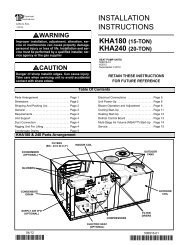
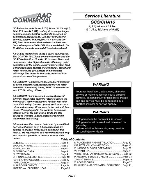
GCS16 series units in the 6, 7.5, 10 and <strong>12.5</strong> ton (21,26.4, 35.2 and 44.0 kW) cooling sizes are packagedcombination gas heat/dx cool units designed forcommercial applications. Gas heat exchanger in160,000, 200,000 and 270,000 (46.9, 58.6 and 79.1kW) Btuh input sizes. Optional electric heat sectionswith inputs of 10 to 50 kW are available in the<strong>CHA16</strong> series units and install inside the cabinet.<strong>Service</strong> LiteratureGCS/<strong>CHA16</strong>6, 7.5, 10 and <strong>12.5</strong> Ton(21, 26.4, 35.2 and 44.0 kW)All GCS20 model units utilize a scroll compressor.The GCS/<strong>CHA16</strong>-072 has cone compressor and theGCS/<strong>CHA16</strong>-090, -120 and -150 has two. The scrollcompressor offer high volumetric efficiency, quietoperation and the ability to start under system load.Continuous flank contact, maintained by centrifugalforce, minimizes gas leakage and maximizesefficiency. The motor is internally protected fromexcessive current temperature.All GCS/<strong>CHA16</strong> models are designed for horizontalor down discharge application and may be fittedwith RMF16 mounting frame, REMD16 economizerand RTD11 ceiling diffuser.All GCS/<strong>CHA16</strong> are designed to accept severaldifferent thermostat control systems such as theHoneywell T7300 or Honeywell T8621D with minimumfield wiring. Control options such as economizerand warm up kit connect to the unit with jackplugs.When plugged in the controls become anintegral part of the unit wiring. Units are alsoequipped with low voltage pigtails to facilitatethermostat field wiring.Information in this manual is for use by a qualifiedservice technician only. All specifications aresubject to change. Procedures outlined in thismanual are represented as a recommendation onlyand do not supersede or replace local or statecodes.GENERAL .......................................................Page 1SPECIFICATIONS............................................Page 2HIGH ALTITUDE...............................................Page 3ELECTRICAL DATA............ ............................Page 4BLOWER DATA.............................................. .Page 4OPTIONAL ACCESSORIES....................... .....Page 10PARTS ARRANGEMENT.................................Page 12I APPLICATION................................................Page 14II UNIT COMPONENTS....................................Page 14III OPTIONAL ELECTRIC HEAT.......................Page 25Table of ContentsWARNINGImproper installation, adjustment, alteration,service or maintenance can cause propertydamage, personal injury or loss of life. Installationand service must be performend by aqualified installer or service agency.WARNINGRefrigerant can be harmful if it is inhaled.Refrigerant must be used and recovered responsibly.Failure to follow this warning may result inpersonal injury or death.IV PLACEMENT AND INSTALLATION.............Page 30V ELECTRICAL CONNECTIONS.....................Page 30VI INDOOR BLOWER OPERATION.................Page 30VII START UP....................................................Page 31VIII REFRIGERATION SERVICE CHECKS......Page 32IX HEATING SERVICE CHECKS......................Page 33X MAINTENANCE............................................. Page 35XI ACCESSORIES.............................................Page 37XII WIRING AND OPERATION SEQUENCE....Page 41Page 1
Page 2
Page 3
Page 4
Page 5
Page 6
Page 7
Page 8
Page 9
Page 10
Page 11
Page 12
Page 13
I-APPLICATIONGCS/<strong>CHA16</strong> 6 and 7.5 ton units are available in one cabinetsize and GCS/<strong>CHA16</strong> 10 and <strong>12.5</strong> ton units are available inon size. All models are applicable for commercial threephase installations. GCS/<strong>CHA16</strong> models are factoryequipped with the hardware required for installing optionalthermostat control systems like the T7300 or T8621D (referto the Engineering Handbook for more specific applicationdata).II-UNIT COMPONENTSGCS16 unit components are shown in figure 1. <strong>CHA16</strong> unitcomponents are shown in figure 2.A-Control Box ComponentsThe GCS/<strong>CHA16</strong> control box is shown in figures 3 and 4.The control box is located in the upper portion of the compressorcompartment behind the compressor compartmentaccess panel. Note that the burner ignition control (GCSmodels only) is located in the heating control section locatedjust above the manifold/burner assembly.The condenser fan can be accessed by removing the fangrill located on the top of the unit.The indoor blower access panel (all units) is located to theleft side of the heating compartment access.1-Transformer T1All GCS/<strong>CHA16</strong>-072/090/120/150 units use a single linevoltage to 24VAC transformer mounted in the control box.The transformer supplies power to control circuits in the unit.Transformers are rated at 70VA and are protected by a 3.5amp circuit breaker (CB). Transformers use two primaryvoltage taps as shown in figure 5.4-Outdoor Fan Relay K10Outdoor fan relay K10 used in GCS/<strong>CHA16</strong>-090/120/150units, is a DPDT relay with a 24V coil. K10 energizesoutdoor fans B4 and B5 (120/150 units) in response tothermostat demand.5-Cooling Contactor K1 & K2K1 and K2 are 24V coil contactors used to energize thecompressor(s) in response to thermostat demand. In GCS/<strong>CHA16</strong>-072 units, K1 energizes condenser fan B4 alongwith compressor B1 and K2 energizes compressor B2 inresponse to second stage cooling demand. All GCS/<strong>CHA16</strong>-072/090/120/150 units use three-pole-double-breakcontactors.CAUTIONRemove all power to disconnect beforeservicing.Electrical shock resulting in death or injurymay result if power is not disconnected.6-Indoor Blower Contactor K3All GCS/<strong>CHA16</strong>-072/090/120/150 units use a three-poledouble brake contactor to energize the indoor blower andoptional economizer. The coil is energized by a blowerdemand from indoor thermostat terminal “G” (coolingdemand or fan switch in “ON” position).7-Condenser Fan Motor Capacitor C1 & C2GCS/<strong>CHA16</strong>-072/090/120/150 series units use single phasePSC condenser fan motors. See condenser fan motornameplate for capacitor ratings.B-Heat Control Section (GCS Only)2-Terminal Strip TB34Terminal strip TB34 distributes 24V power from transformerT1 to the control box components.3-Transformer T3 (G & J Voltage Only)All GCS16-072/090/120/150 G and J units use one 230VACtransformer mounted in the control box. The transformer hasan output rating of 115VA .55A @ 230V. T3 transformersupplies 230VAC power to combustion air inducer motor B6.Page 14
Page 15
ÉÉÉÉÉÉÉÉÉÉÉÉÉÉÉÉ ÉÉÉÉÉÉ ÉÉÉÉÉÉÉÉÉÉÉÉÉÉÉÉÉÉÉÉÉÉÉÉÉÉÉÉÉÉÉÉÉÉÉÉÉÉÉÉÉÉÉÉÉÉÉÉ ÉÉÉÉÉÉÉÉÉÉÉÉÉÉÉÉÉÉÉÉÉÉÉÉ ÉÉÉÉÉÉÉÉÉÉÉÉÉÉ ÉÉÉÉ ÉÉÉÉÉÉÉÉÉÉÉÉÉÉÉÉÉÉÉÉÉÉÉÉÉÉÉÉÉÉÉÉÉÉÉÉÉÉÉÉÉÉÉÉÉÉÉÉÉÉÉÉÉÉÉÉÉÉÉÉÉÉÉÉÉÉÉÉÉÉÉÉÉÉ ÉÉÉÉÉÉÉÉÉÉÉÉÉÉÉÉÉÉÉÉÉÉÉÉÉÉÉÉÉÉÉÉÉÉÉÉÉÉÉÉÉÉÉÉÉÉÉÉÉÉÉÉÉÉÉÉÉÉ ÉÉÉÉÉÉ ÉÉÉÉÉÉÉÉÉÉÉÉÉÉÉÉÉÉÉÉÉÉÉÉÉÉÉÉÉÉÉÉÉÉÉÉÉÉÉÉÉÉÉÉÉÉÉÉÉÉÉÉÉÉÉÉÉÉÉÉÉÉÉÉÉÉÉÉÉÉÉÉÉÉÉÉÉÉÉÉÉÉÉÉÉÉÉÉÉÉÉÉÉÉÉÉÉÉÉÉÉÉÉ ÉÉÉÉÉÉÉÉÉÉÉÉÉÉÉÉÉ ÉÉÉÉÉÉÉÉÉÉÉÉÉÉÉPage 16
Page 17
2-Burner Assembly (Figure 13)The burners are controlled by the spark electrode, flamesensing electrode, gas valve GV1 and combustion airblower B6. The spark electrode, flame sensing electrodeand gas valve GV1 are directly controlled by ignition controlA3.a-BurnersAll units use inshot burners. Burners are factory set and donot require adjustment. Burner shutters are designed to befully open only. Units are furnished with a peep hole withcover in the access panel for flame viewing. Always operateunit with access panel in place. Burners can be individuallyremoved for service. Burner maintenance and service isdetailed in the MAINTENANCE section of this manual.4-Primary High Temperature Limit S10S10 is the primary limit for gas heat. See figure 15 for bothtypes used. On GCS16-090-1 models units, S10 is locatedin the heating compartment and mounted to the lowerportion of the panel dividing the heating compartment fromthe blower compartment. On GCS16-072 and GCS16-090-2models, S20 is located in the return air area. On GCS16-120/150 models, S10 is located in the blower compartment.Primary limit S10 is wired in series with the burner controlA3. S10 N.C. contacts open to de-energize the ignitioncontrol when excessive heat is reached in the heat exchanger.At the same time, the N.O. contacts close energizingK20 blower limit relay, which in turn energizes the blowerrelay K3 energizing indoor blower B3. See table 2 for factoryset point. Stick type limit used on GCS16-072 and 090-2models must be installed with limit face in DOWN position.b-OrificeEach burner uses an orifice which is matched to the burnerinput. The orifice is threaded into the manifold. The burner issupported by the orifice and will easily slide off for service.Each orifice and burner are sized specifically to the unit.3-Flame Rollout Switch S47 (figure 14)Flame rollout switch S47 is a high temperature limit locatedjust above the burner on all units. See figure 13. The limit isa N.C. SPST manual re-set thermostat connected in serieswith ignition control A3. When S47 senses flame rollout,ignition control immediately closes the gas valve. The switchis factory set to open at 180 o and cannot be adjusted.Table 2GCS16 Unit S10 Set Point o S21 Set Point o072-1 200 175090-1 180 150090-2 200 175120-1 180 150120-2 170 150150-1 170 1505-Secondary Limit S21All GCS16 model units are equipped with a secondary limit(disc type limit figure 15). On GCS16-072/090 models, S21is located in the blower compartment. On GCS16-120/150models, S21 is located in the return air (behind filters). Thelimit is auto-re-set thermostat which opens on temperaturerise. S21 is wired in series with the ignition control. The limitis used to de-energize the ignition control and shut down theunit when temperature in the blower compartment becomestoo high. The limit is factory set and is not adjustable. Seetable 2. This is a safety shutoff function of this unit and mustnever be bypassed.Page 18
Page 19
Page 20
Page 21
Page 22
Page 23
The scroll compressor is tolerant to the effects of liquidreturn. If liquid enters the scrolls, the orbiting scroll isallowed to separate from the stationay scroll. The liquid isworked toward the center of the scroll and is discharged. Ifthe compressor is replace, conventional cleanup practicesmust be used.Due to its efficiency, the scroll compressor is capable ofdrawing a much deeper vacuum than reciprocating compressors.Deep vacuum operation can cause internal fusitearcing rsulting in damaged internal parts and compressorfailure. It is permissible to “pump-down” the system usingthe compressor but never use a scroll compressor fordrawing a vacuum on the system. The type of damage canbe detected and will result in denial of warranty claims.3-Indoor Blower Motor B3All GCS/<strong>CHA16</strong> model units use three-phase, PSC, beltdriven blower motors. See motor nameplate or ELECTRI-CAL DATA section for motor specifications.4-Evaporator CoilAll GCS/<strong>CHA16</strong> model units have a single slab evaporatorcoil. The ocil in the GCS/<strong>CHA16</strong>-072/090/120 has threerows and the GCS/<strong>CHA16</strong>-150 has four rows, of rifledcopper tubes fitted with ripple-edged aluminum fins. AThermal Expansion Valve (TXV) feeds multiple parallelcircuits through the coil. See figure 27.CAUTIONThe head of a scroll compressor may be hotsince it is in constant contact with dischargegas.Contact could result in serious burns.For compressor specifications see compressor nameplateor ELECTRICAL DATA section in this manual. All compressorsare protected by internal overload protection circuitry.2-Condenser Fan and Motor B4 & B5The specificiations section in this manual shows the specificationsof condenser fans used in GCS/<strong>CHA16</strong>s’. Thecondenser fan is controlled by cooling contactor K1.Page 24
Page 25
° ° Page 26
° ° Page 27
Page 28
DL5DL4K9K19K18K17K16K15DL2 Page 29
Page 30
Page 31
Page 32
Page 33
Page 34
Page 35
Page 36
° °° ° Page 37
° ° Page 38
Page 39
Page 40
Page 41
Page 42
Page 43
Page 44
Page 45
Page 46
Page 47
Page 48
Page 49