LF24 Unit Heater (30-75) Installation Instructions - Allied Commercial
LF24 Unit Heater (30-75) Installation Instructions - Allied Commercial
LF24 Unit Heater (30-75) Installation Instructions - Allied Commercial

You also want an ePaper? Increase the reach of your titles
YUMPU automatically turns print PDFs into web optimized ePapers that Google loves.
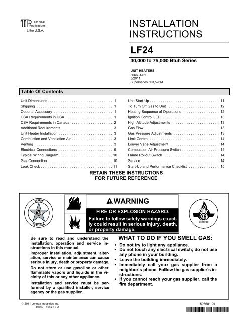
If indoor air is to be used for combustion, it must be free ofthe following substances or the life of the heat exchangerwill be adversely affected: chlorine, carbon tetrachloride,cleaning solvent, halogen refrigerants, acids, cementsand glues, printing inks, fluorides, paint removers,varnishes, or any other corrosives.VentingNOTE − The vent is a passageway, vertical or nearly so,used to convey flue gases from an appliance, or its ventconnector, to the outside atmosphere. The ventconnector is the pipe or duct that connects afuel−gas−burning appliance to a vent or chimney.NOTE − Local codes may supersede any of theseprovisions.GENERAL RECOMMENDATIONS ANDREQUIREMENTS<strong>Unit</strong> heaters must be vented in compliance with the latestedition of the National Fuel Gas Code (NFPA 54 / ANSIZ223.1) in the USA and with CSA−B149.1 codes inCanada, as well as applicable provisions of local buildingcodes, and the following instructions.A stamped/extruded metal transition is supplied withthis certified unit. It must not be modified or alteredand must be installed on the outlet of the combustionair inducer assembly prior to the installation of thevent connector. Failure to comply with thisrequirement will void the certification of the unit bythe approval agencies.A single−wall vent connector may be used between thefurnace and the vertical vent pipe in all applications;however, single−wall vent material cannot be used forvertical vent piping in residential applications.UL−approved Category III venting materials must beused in all residential applications which includehorizontal vent piping.A single−wall vent pipe used as a vent connector inresidential or commercial applications, or as a verticalvent in commercial applications, must have all seams andjoints sealed with pressure−sensitive aluminum tape orsilicone rubber sealant. Aluminum tape must meet theprovisions of SMACNA AFTS−100−73 Standards. Thealuminum tape must have a temperature rating of 400°F(204°C). Silicone rubber sealant must have atemperature rating of 482°F (250°C), i.e., Dow CorningRTV−736 or equivalent.All joints must be secured with at least twocorrosion−resistant screws. All joints must be checked forgas tightness after installation. Single−wall vent pipe usedas vertical vent in commercial applications must not passthrough any attic, interior wall, concealed space, or floor.VERTICAL VENTS USING METAL VENT PIPE −COMMERCIAL AND RESIDENTIAL INSTALLATIONSThese compact unit heaters are listed as Category 1appliances for vertical vent installations.1 − These unit heaters are to be used with NFPA− orANSI−approved chimneys or U.L.−listed type B−1 gasvents, or listed chimney lining systems for gasventing where applicable, as well as themodifications and limitations listed in figure 2. Sealsingle−wall vent material according to GeneralRecommendations and Requirements section.2 − The vent connector shall be 3" (76mm) diameter on<strong>30</strong>K and 45K Btuh units and 4" (102mm) diameter on60K and <strong>75</strong>K Btuh units. In all cases, a flue transitionpiece (supplied) is required to fit over the outlet of theinduced draft assembly on the appliance.3 − Keep the vent connector runs as short as possiblewith a minimum number of elbows. Refer to thecurrent edition of ANSI Z223.1 or CSA−B149installation compliance codes for maximum vent andvent connector lengths. Horizontal run of the ventconnector from the combustion air inducer to thechimney/vent cannot exceed the values in table 2.Single−wall vent connector shall not be insulated.4 − The entire length of a single−wall metal ventconnector shall be readily accessible for inspection,cleaning and replacement.TABLE 2MAXIMUM HORIZONTAL VENT CONNECTORAND HORIZONTAL VENT LENGTHSNumber. ofFeetMetersElbows1 25 7.62 20 6.13 15 4.64 10 3.05 5 1.5Page 4
SINGLE−WALL VENT PIPE WITHSINGLE−WALL TERMINATIONVENT TERMINATION ON SINGLE−WALL VERTICAL VENT RUNS(<strong>Commercial</strong> Applications Only)SINGLE−WALL VENT PIPE WITHDOUBLE−WALL (TYPE B−1) TERMINATIONROOF FLASHINGROOF PITCHEDFROM 0" TO 45"ROOF FLASHINGROOF PITCHEDFROM 0" TO 45"12" MAX2" CLEARANCETHIMBLESEAL JOINT BETWEEN SINGLE−WALL VENT AND B" VENT TER-MINATION AND THE OPEN SPACE BETWEEN THE SINGLE WALLVENT PIPE AND THE OUTER PIPE OF THE B" VENT TERMINATION.FIGURE 2CLEARANCE TO BEAS SPECIFIED ONTYPE B" VENT PIPE.5 − The unit may be vented vertically as a singleappliance or in a common vent with other gas−firedappliances. In common venting situations, ventconnectors for other appliances must maintain a 4"(102mm) vertical separation between the ventconnectors. Refer to common venting tables in thecurrent editions of ANSI Z223.1 or CSA−B149installation compliance codes for proper vent size.6 − Clearance to combustible material is 6" (152mm) forsingle−wall vent material except where a listedclearance thimble is used. Clearance to combustiblematerial for type B−1 vent or factory−built chimney isper manufacturer’s instructions.7 − The vent connector shall be supported without anydips or sags. Vertical vents shall be supported inaccordance with their listing and manufacturers’instructions. All horizontal vent connector runs shallhave a slope up to the vertical vent of at least 1/4" perfoot (1mm per 50mm).8 − All vertical type B−1 vents, single−wall vertical vents(commercial applications), or listed chimney liningsystems must be terminated with a UL−listed (orother equivalent agency) vent cap or listed roofassembly.9 − The vent must extend at least 3 feet (1m) above thehighest point where it passes through a roof of abuilding. The vent must also extend at least 2 feet(1m) higher than any part of a building within ahorizontal distance of 10 feet (3m) unless otherwisespecified by ANSI Z223.1 or CSA−B149 installationcompliance codes. The vent must extend at least 5feet (2m) above the highest connected equipmentflue collar.HORIZONTAL VENTINGNOTE − Common venting is not allowed when horizontallyventing the unit heater.If the <strong>LF24</strong> unit heater is to be horizontally vented, apositive pressure may be created in the vent. The unitheater, when installed with horizontal venting, willperform as a category III appliance.1 − In residential applications which includehorizontal venting, use only special ventmaterials approved for use with Category IIIappliances. Refer to table 3 for ventingcomponents.2 − The vent pipe diameter for horizontal installationsshall be 3" (76mm) on <strong>30</strong>K and 45K Btuh units and 4"(100mm) on 60K and <strong>75</strong>K Btuh units. In most cases,a flue transition piece (supplied) is required to fit overthe outlet of the induced draft assembly on theappliance.3 − The minimum horizontal vent length is 5 feet (2m).4 − Refer to table 2 for maximum horizontal vent lengths.5 − If possible, do not terminate the horizontal ventthrough a wall that is exposed to prevailing wind.Exposure to excessive winds can affect unitperformance. If such a termination is necessary, usea wind block to protect the vent termination fromdirect winds.6 − Horizontal vent termination must be free fromobstructions and at least 12" (<strong>30</strong>5mm) above gradelevel and maximum snow height.Page 5
NOTE − Minimumhorizontal vent length is5 ft. This does notinclude termination tee.Refer to table 2 formaximum length andnumber of elbows.COMMON VENTINGNOT ALLOWED WHENHORIZONTALLYVENTING THEUNIT HEATER.RESIDENTIAL APPLICATIONS −− Venting must belisted special vent for Category III appliances.COMMERCIAL APPLICATIONS −− Venting may besingle−wall (26 GSG) galvanized or equivalentstainless steel vent pipe sealed per these instructions,OR listed special vent for Category III appliances.SLOPE = 1/4 IN. PER FOOT RUN MAXIMUM.NOTE − Minimumhorizontal vent length is5 ft. This does notinclude termination tee.Refer to table 2 formaximum length andnumber of elbows.COMMON VENTINGNOT ALLOWED WHENHORIZONTALLYVENTING THE UNITHEATER.CONDENSATE DRAIN THROUGH TEE PIPE AND DRAIN LOOPDOWNWARD SLOPE ON HORIZONTAL VENT − RESIDENTIAL −OR COMMERCIAL APPLICATIONCategory IIIadaptor mustbe installedbeforeoptionalelbow(if used).DRAIN LOOP WITHWATER TRAP TOCONDENSATE DRAIN(Provided by installer)FIGURE 4FIGURE 5DRAIN TEE12 INCHESMIN. (<strong>30</strong>.5 CM)12 INCHESMIN. (<strong>30</strong>.5 CM)LISTED THIMBLETHROUGHCOMBUSTIBLEWALLVENTTERMINATIONTEECONDENSATE DRAIN THROUGH VENT TERMINATIONDOWNWARD SLOPE ON HORIZONTAL VENT−RESIDENTIAL OR COMMERCIAL APPLICATIONELBOWOPTIONALRESIDENTIAL APPLICATIONS −− Venting must be listed special ventfor Category III appliances.COMMERCIAL APPLICATIONS −− Venting may be single−wall (26GSG) galvanized or equivalent stainless steel vent pipe sealed perthese instructions, OR listed special vent for Category III appliances.SLOPE = 1/4 IN. PER FOOT RUN MAXIMUM.DOUBLEMALEADAPTER(Cat. IIIkits only)TABLE 3Category III Horizontal Venting Components(Required for Horizontal Vent Applications)<strong>Unit</strong> Catalog Number Model Number Description<strong>75</strong>W66 C5VENT3KD 3" downward sloped Cat III vent kit<strong>75</strong>W62 C5VENT3KU 3" upward sloped Cat III vent kit<strong>LF24</strong>−<strong>30</strong><strong>75</strong>W70 C5VENT3E 3" 90° elbow Cat III (optional)<strong>LF24</strong>−45<strong>75</strong>W74 C5VENT3P6 3" straight pipe (length = 6")<strong>75</strong>W<strong>75</strong> C5VENT3P12 3" straight pipe (length = 12")<strong>75</strong>W76 C5VENT3P36 3" straight pipe (length = 36")<strong>75</strong>W63 C5VENT4KU 4" upward sloped Cat III vent kit<strong>75</strong>W67 C5VENT4KD 4" downward sloped Cat III vent kit<strong>LF24</strong>−60<strong>75</strong>W71 C5VENT4E 4" 90° elbow Cat III (optional)<strong>LF24</strong>−<strong>75</strong><strong>75</strong>W77 C5VENT4P6 4" straight pipe (length = 6")<strong>75</strong>W78 C5VENT4P6 4" straight pipe (length = 12")<strong>75</strong>W79 C5VENT4P6 4" straight pipe (length = 36")LISTED THIMBLETHROUGHCOMBUSTIBLEWALLVENTTERMINATIONTEEPage 7
Electrical ConnectionsNOTE − Local codes may supersede any of the provisionsoutlined in this instruction.The <strong>LF24</strong> series unit heaters use a direct spark ignitionsystem. There is no pilot necessary as the spark lights themain burner as the gas valve is turned on. The directspark ignition control board emits radio noise as thesparking process is under way. The level of energy maybe sufficient to disturb a logic circuit in a microprocessorcontrolled thermostat. It is recommended that an isolationrelay be used when connecting the unit heaters to amicroprocessor controlled thermostat. Install thethermostat according to instructions provided. Install aseparate fused disconnect switch, with the fuse sizedaccording to blower motor size. Connect wiring throughknockout on the junction box located on the side of theunit heater. Refer to heater wiring diagram for connectioninformation. Use 18 gauge wire or larger for thermostatconnections.NOTE − Electrically ground unit in accordance with localcodes or, in the absence of local codes, in accordancewith the current editions of the ANSI/NFPA No. 70,National Electrical Code or CSA C22.1, CanadianElectrical Code, Part 1.NOTE − Uninsulated ground wires must be wrapped inelectrical tape to avoid damage to the electrical system.Make line voltage connections as shown in figure 7.Connect field wiring as shown on wiring diagram on unit.Also refer to typical diagram in this manual. An additionalthermostat wire must be run to terminal G" on heaterwhen continuous blower is desired.L1NLINE VOLTAGE FIELD WIRINGBLACK WIRE WITH WHITE TAPEORWHITE WIRE WITHOUT TAPEFIGURE 7UNITBLACKBLACKWHITEWHITEPage 9
TYPICAL <strong>LF24</strong>−<strong>30</strong>, 45, 60, & <strong>75</strong> WIRING SCHEMATICGas ConnectionWhen connecting gas supply, the length of the run fromthe meter must be considered in determining the pipe sizeto avoid excessive pressure drop. A line pressure of 7"w.g. (178mm w.g.) for natural gas should be maintainedwhen sizing piping. For correct sizing of piping, consultthe utility having jurisdiction.A drip leg should be installed in the vertical pipe run to theunit. In some localities, codes may require that a manualmain shutoff valve and union (furnished by installer) beinstalled external to the unit. Union must be of the groundjoint type. A drip leg should be readily accessible to permitcleaning and emptying. See figure 8.GAS SUPPLY CONNECTIONGROUNDJOINT UNION1/8 NPTPLUGGEDTAPDRIP LEGMANUALMAIN SHUT−OFF VALVE(Furnished by Installer)GAS FLOWFIGURE 8Page 10
NOTE − If a switch box is mounted over electricalknock−outs on back of unit, leave a minimum of 4"(102mm) clearance between switch box and drip leg.A 1/8" NPT plugged tap shall be installed immediatelyupstream of the gas supply connection to the heater.NOTE − Compounds used on threaded joints of gas pipingmust be resistant to the actions of liquefied petroleumgases.Leak CheckAfter gas piping is completed, carefully check all pipingconnections, (field and factory), for gas leaks. Use a soapsolution or other preferred means.CAUTIONDO NOT use matches, candles, flame or othersources of ignition to check for gas leaks.The appliance must be isolated from the gas supplypiping system by closing its individual manual gas shutoffvalve during any pressure testing of the gas supplysystem at test pressures equal to or less than 1/2 psig(3.45kPa).IMPORTANTThe heater and its individual shut off valve must bedisconnected from the gas supply piping systemduring any pressure testing of that system at testpressures in excess of 1/2 psig (3.45kPa). See figure9.NOTE − In case emergency shutdown is required, shutdown main gas valve and disconnect main power to unit.These devices should be properly labeled by the installer.GAS SUPPLY TO UNIT HEATERMANUAL MAIN SHUT−OFFVALVE WILL NOT HOLDNORMAL TESTPRESSURES OF 1/2 psig(3.45kPa) OR HIGHERCAPUNIT HEATERFIGURE 9DISCONNECT GASVALVE WHEN TESTPRESSURES OF1/2 psig (3.45kPa)OR HIGHER WILLBE USED.<strong>Unit</strong> Start−UpFOR YOUR SAFETY READ BEFORE LIGHTING! WARNINGElectric shock hazard. Can cause injuryor death. Do not use this heater if anypart has been under water. Immediatelycall a qualified service technician to inspectthe furnace and to replace any partof the control system and any gas controlwhich has been under water.! WARNINGDanger of explosion. Can cause injury orproduct or property damage. If overheatingoccurs or if gas supply fails toshut off, shut off the manual gas valve tothe appliance before shutting off electricalsupply.! WARNINGElectric shock hazard. Can cause injuryor death. Before attempting to performany service or maintenance, turn theelectrical power to unit OFF at disconnectswitch(es). <strong>Unit</strong> may have multiple powersupplies.! WARNINGDanger of explosion and fire. Can causeinjury or product or property damage. Youmust follow these instructions exactly.BEFORE LIGHTING smell all around the appliance areafor gas. Be sure to smell next to the floor because somegas is heavier than air and will settle on the floor.Use only your hand to push in or turn the gas control knob.Never use tools. If the knob will not push in or turn byhand, do not try to repair it, call a qualified servicetechnician. Force or attempted repair may result in a fireor explosion.These unit heaters are equipped with an automatic sparkignition system. There is no pilot. In case of a safetyshutdown, move thermostat switch to OFF, then returnthe thermostat switch to HEAT position.<strong>LF24</strong> unit heaters are equipped with an automatic sparkignition system. There is no pilot. In case of a safetyshutdown, move thermostat switch to OFF, then returnthe thermostat switch to HEAT position.Page 11
OPERATION OF HONEYWELL VR8205 SERIES GASVALVE (FIGURE 10)NOTE − STOP! Read the safety information at thebeginning of this section.1 − Set thermostat to lowest setting.HONEYWELL VR8205 SERIES GAS VALVEMANIFOLD PRESSURE ADJUSTMENT SCREWOFFFIGURE 102 − Turn off all electrical power to appliance.3 − This appliance is equipped with an ignition devicewhich automatically lights burners. DO NOTattempt to light the burners manually.4 − Turn the manual knob on gas valve clockwise toOFF. Do not force.5 − Wait five minutes to clear out any gas. If you thensmell gas, STOP! Immediately call yourgas supplier from a neighbor’s phone. Follow thegas supplier’s instructions. If you do not smellgas, go to next step.6 − Turn manual knob on gas valve counterclockwise toON.7 − Turn on all electric power to unit.8 − Set thermostat to desired setting.9 − The combustion air inducer (CAI) will start. Theburners will light within 40 seconds.10 − If unit does not light first time (gas line not fullypurged) it will attempt up to two more ignitions beforelocking out.11 − If lockout occurs, repeat steps 1 through 9.12 − If appliance still will not operate, follow theinstructions To Turn Off Gas to <strong>Unit</strong>" and call yourservice technician or gas supplier.ONGAS VALVE SHOWN IN OFF POSITIONTo Turn Off Gas to <strong>Unit</strong>1 − Set thermostat to lowest level.2 − Turn off all electrical power to unit if service is to beperformed.3 − Turn knob on gas valve 90° clockwise to OFF.Heating Sequence of Operation1 − When the thermostat calls for heat, the combustionair inducer starts immediately.2 − Combustion air pressure switch proves induceroperation before allowing power to the ignitioncontroller. This switch is factory set and noadjustment is necessary.3 − After pre−purge of approximately <strong>30</strong> seconds, thespark ignition is energized and the solenoid valvesopen in the gas valve.4 − The spark then ignites the gas, the ignition sensorproves the flame and the combustion processcontinues.5 − In the event that the flame is not detected after thefirst 10−second trial for ignition, the controller willrepeat steps 3 and 4 an additional two times beforelocking out the gas valve. Ignition control will thenautomatically repeat steps 3, 4, and 5 after 60minutes.NOTE − To interrupt the 60−minute lockout period,move thermostat from Heat" to OFF" then back toHeat." Heating sequence then restarts at step 1.6 − The burners must light without noticeable crossoverdelay. There must be no flame lifting from the burnerheads, flashback or burning within the burner. Theflames should be predominantly blue in color andshould be approximately centered in the tubes withno apparent impingement taking place.7 − The ignition control will energize the fanapproximately 45 seconds after ignition isestablished.8 − After the thermostat demand is satisfied the gasvalve is closed. Five seconds after the demand issatisfied, the combustion air inducer is shut off.9 − The ignition control will shut off the system fanapproximately 150 seconds after the gas valve isde-energized.Page 12
Ignition Control LEDThe ignition control contains a green LED which indicatesthe following:TABLE 4IGNITION CONTROL LEDLEDSlow. Flash*Fast FlashUNIT OPERATIONNormal Operation − No call for heatNormal Operation − Call for heat2 Flashes System lockout − failed to detect or sustain flame3 FlashesPressure switch failed closed before CAI is energizedor failed open after CAI is energized4 Flashes High limit or rollout switch open5 Flashes Flame sensed and gas valve not energizedSteady OffSteady OnLoss of PowerIgnition control failure*When thermostat is placed in continuous fan mode LED willslowly flash.High Altitude Adjustments<strong>Unit</strong>s may be fired at full input up to 2000 feet. (610m)above sea level. Above 2000 feet (610m), manifoldpressure must be adjusted on some units. Adjustpressure regulator to pressure shown in table 5 for naturalgas and table 6 for LP/propane gas.INPUT(BTUH)TABLE 5NATURAL GAS MANIFOLD PRESSURES[inch w.g. (kPa)]0−3500(0−1067)<strong>30</strong> 3.5(0.87)*45 3.5(0.87)*60 3.5(0.87)*<strong>75</strong> 3.5(0.87)**No adjustment required.Altitude in Feet (Meters)35−4500(1067−1372)3.5(0.87)*3.5(0.87)*3.5(0.87)*3.4(0.85)45−5500(1372−1676)3.5(0.87)*3.5(0.87)*3.5(0.87)*3.3(0.82)55−6500(1676−1981)3.5(0.87)*3.5(0.87)*3.5(0.87)*3.2(0.80)65−<strong>75</strong>00(1981−2286)3.5(0.87)*3.4(0.85)3.5(0.87)*3.1(0.77)TABLE 6LP/PROPANE GAS MANIFOLD PRESSURES[inch w.g. (kPa)]Altitude in Feet (Meters)INPUT(BTUH)<strong>30</strong>4560<strong>75</strong>0−3500(0 −1067)9.5(2.37)*9.5(2.37)*9.5(2.37)*9.5(2.37)**No adjustment required.3501 −4500(1067−1372)9.5(2.37)*9.5(2.37)*9.5(2.37)*9.2(2.28)4501 −5500(1372−1676)9.5(2.37)*9.5(2.37)*9.5(2.37)*8.9(2.21)5501 −6500(1676−1981)9.5(2.37)*9.5(2.37)*9.5(2.37)*8.6(2.13)6501 −<strong>75</strong>00(1981−2286)9.5(2.37)*9.2(2.28)9.5(2.37)*8.3(2.06)NOTE − A natural to LP/propane gas changeover kit isrequired to convert unit. Refer to the installationinstructions supplied with the changeover kit forconversion procedure.If unit is installed at an altitude greater than <strong>75</strong>00 feet(1372m), unit must be derated by four percent for eachadditional 1000 feet (<strong>30</strong>5m) above <strong>75</strong>00 feet or asspecified by local authority having jurisdiction.The combustion air inducer proving switch is factory set.No adjustment is necessary.Gas FlowTo check for proper gas flow to the combustion chamber,determine the Btu input from the appliance rating plate.Divide this input rating by the Btu per cubic feet ofavailable gas. Result is the required number of cubic feetper hour. Determine the flow of gas through the gas meterfor two minutes and multiply by <strong>30</strong> to get the hourly flow ofgas.Gas Pressure Adjustment1 − Check gas line pressure with unit firing at maximumrate. A minimum of 5" (127mm) w.g. for natural gasor 10.4" (264mm) w.g. for LP/propane gas should bemaintained for proper unit operation.2 − After line pressure has been checked and adjusted,check regulator pressure. Correct manifold pressureis shown on the unit rating plate. See figures 9 and10 for gas pressure adjustment screw location. Anatural gas to LP/propane gas changeover kit isrequired to convert the unit in the field. Refer toinstallation instructions provided with changeover kitfor conversion procedure.Page 13
Limit ControlThe limit control switch is factory−set and is notfield−adjustable.Louver Vane AdjustmentRotate louver vanes to direct airflow upward, downward,straight, or any combination of these directions. Whenunit is installed in an inverted position, louvers may bepositioned in the same manner.Combustion Air Pressure SwitchThis pressure switch checks for proper combustion airinducer operation before allowing an ignition trial. Theswitch is factory−set. No field adjustment is necessary.Flame Rollout SwitchThe flame rollout switch(es) are located on the burner boxtop, behind the ignition control board. This normallyclosed switch opens on a temperature rise. Check foradequate combustion air before manually resettingswitch.ServiceCAUTIONTurn off gas and electrical power to unit before performingany maintenance or service operations onthis unit. Remember to follow lighting instructionswhen putting unit back into operation after serviceor maintenance.The unit heater and vent system shall be inspected once ayear by a licensed professional service technician, orequivalent.BURNERS1 − Periodically examine burner flames for properappearance during the heating season.2 − Before each heating season examine the burners forany deposits or blockage that may have occurred.3 − Clean burners as follows:a − Turn off both electrical and gas supplies to unit.b − Disconnect gas supply piping, high tension andsensor leads. Remove gas manifold. Removeburner tray.c − Clean burners as necessary. Make sure thatburner heads line up properly to ensure flamecrossover. Check spark gap on electrode andadjust if required. The gap should be between0.110" and 0.140" (3mm to 4mm). The gap maybe checked with appropriately sized twist drillsor feeler gauges.d − Reinstall burner tray, gas manifold, high tensionand sensor leads. Reconnect gas supplypiping.e − Restore electrical power and gas supply. Followlighting instructions to light unit. Check burnerflame.FLUE PASSAGEWAY AND FLUE BOXThe flue passages and flue box should be inspected andcleaned prior to each heating season. The sequence ofoperation should be as follows:1 − Turn off both electrical and gas supply to unit.2 − Disconnect combustion air inducer wiring.3 − Remove screws securing flue box to unit. Removeflue box. If necessary, remove inducer assemblyfrom flue box. Clean flue box with wire brush.4 − Remove turbulator retention bracket andturbulators. Clean turbulators with wire brush.5 − Remove burners as described in Burners" section.6 − Clean tubes with a wire brush.7 − Reassemble unit. The combustion air and flue boxgaskets should also be replaced during reassembly.8 − Restore electrical power and gas supply. Followlighting instructions to light unit. Check operation ofunit.COMBUSTION AIR INDUCERUnder normal operating conditions, the combustion airinducer should be checked and cleaned prior to theheating season with the power supply disconnected. Usea small brush to clean inducer wheel.ELECTRICAL1 − Check all wiring for loose connections.2 − Check for correct voltage at unit (unit operating).3 − Check amperage draw.FLUE AND CHIMNEYCheck all vent and vent connector joints for tightness.Ensure that connections are sealed and that there are noblockages.FAILURE TO OPERATEIf unit fails to operate check the following:Page 14
1 − Is thermostat calling for heat?2 − Is main disconnect closed?3 − Is there a breaker tripped or a fuse blown?4 − Is gas turned on at meter?5 − Is manual shutoff valve open?6 − Is unit ignition system in lock out? If unit locks outagain, call service technician to inspect unit.7 − Is pressure switch closed? Obstructed flue willcause unit to shut off at pressure switch. Check fluepassage and outlet.SAFETY SHUT−OFF VALVE TESTThe safety shut−off valve test procedure is as follows:1 − Turn off the manual gas valve.2 − Set the thermostat to call for heat.3 − System begins normal sequence of operation.4 − After approximately <strong>30</strong> seconds (pre purge period)the LED will fast flash indicating the gas valve ispowered.Job Name:Job Location:Installer:<strong>Unit</strong> Model No.:START−UP AND PERFORMANCE CHECKLISTJob No.:City:City:Serial No.:5 − After 10 seconds, the gas valve closes and steps 4and 5 will repeat two additional times before lockingout the gas valve, which will be indicated by twoflashes on the LED.6 − To restart the system, de−energize the thermostatcall for heat and follow the operating instructionsunder <strong>Unit</strong> Start−Up and Operation.REPAIR PARTSWhen ordering repair parts, include the complete unitmodel number listed on the unit rating plate. For example:<strong>LF24</strong>−45A−1. Contact the installing dealer, or visitwww.lennox.com or call 1−800−9LENNOX for a list of theLennox dealers in the area.Date:State/Province:State/Province:Service Technician:Electrical Connections Tight?Supply VoltageBlower Motor Lubrication O.K.?Gas Piping Connections Tight & Leak−Tested?Blower Motor AmpsFurnace Btu InputLine PressureManifold Pressurew.c.Air Shutters Properly Adjusted (If Installed)?Flue Connections Tight?Fan Timer Operation Checked?THERMOSTATCalibrated?Heat Anticipator Properly Set?Level?Page 15