K-Series (2-7.5 KGA) Installation Instructions - Allied Commercial
K-Series (2-7.5 KGA) Installation Instructions - Allied Commercial
K-Series (2-7.5 KGA) Installation Instructions - Allied Commercial

Create successful ePaper yourself
Turn your PDF publications into a flip-book with our unique Google optimized e-Paper software.
Litho U.S.A.2012WARNINGImproper installation, adjustment, alteration, serviceor maintenance can cause property damage,personal injury or loss of life. <strong>Installation</strong> and servicemust be performed by a qualified installer, serviceagency or the gas supplierCAUTIONDanger of sharp metallic edges. Can cause injury.Take care when servicing unit to avoid accidentalcontact with sharp edges.Table Of ContentsDimensions . . . . . . . . . . . . . . . . . . . . . . . . . . . . . . . . . Page 2Parts Arrangements . . . . . . . . . . . . . . . . . . . . . . . . . Page 3Shipping and Packing List . . . . . . . . . . . . . . . . . . . . Page 4General . . . . . . . . . . . . . . . . . . . . . . . . . . . . . . . . . . . . Page 4Requirements . . . . . . . . . . . . . . . . . . . . . . . . . . . . . . . Page 4Unit Support . . . . . . . . . . . . . . . . . . . . . . . . . . . . . . . . Page 5Duct Connection . . . . . . . . . . . . . . . . . . . . . . . . . . . . Page 5Rigging Unit For Lifting . . . . . . . . . . . . . . . . . . . . . . . Page 5Horizontal Air Discharge . . . . . . . . . . . . . . . . . . . . . . Page 6Condensate Drains . . . . . . . . . . . . . . . . . . . . . . . . . . Page 6Gas Piping . . . . . . . . . . . . . . . . . . . . . . . . . . . . . . . . . Page 8Pressure Test Gas Piping . . . . . . . . . . . . . . . . . . . . . Page 8INSTALLATIONINSTRUCTIONS<strong>KGA</strong>/KCA024<strong>KGA</strong>/KCA030<strong>KGA</strong>/KCA036<strong>KGA</strong>/KCA048<strong>KGA</strong>/KCA060<strong>KGA</strong>/KCA072<strong>KGA</strong>/KCA0902, 2−1/2, 3, 4, 5, 6 and 7−1/2 TonGAS AND COOLING PACKAGED UNITS506001−014/2012Supersedes 9/2011High Altitude Derate . . . . . . . . . . . . . . . . . . . . . . . . . Page 9Electrical Connections . . . . . . . . . . . . . . . . . . . . . . . Page 9Blower Operation and Adjustments . . . . . . . . . . . . Page 10Cooling Start−Up . . . . . . . . . . . . . . . . . . . . . . . . . . . . Page 29Gas Heat Start−Up . . . . . . . . . . . . . . . . . . . . . . . . . . . Page 31Heating Operation and Adjustments . . . . . . . . . . . . Page 32Electric Heat Start−Up . . . . . . . . . . . . . . . . . . . . . . . . Page 33Service . . . . . . . . . . . . . . . . . . . . . . . . . . . . . . . . . . . . Page 33RETAIN THESE INSTRUCTIONS FOR FUTURE REFERENCETG SHOWN04/12506001−01
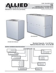
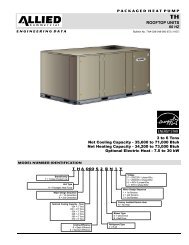
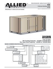
<strong>KGA</strong>/KCA024, 030, 036, 048, 060, 072, & KG 090 DIMENSIONS in. − Gas heat section shown45(1143)47 (1192)BASE5−5/8(143)AADD11(279)16−1/4(413)7 (178) BOTTOMRETURNAIROPENING29(737)6−5/8(168)26−1/2(673)BOTTOMSUPPLYAIROPENING18(457)5 (102)20(508)FFBOTTOMCONDENSATEOUTLETCENTEROFGRAVITYTOP VIEW (Base)83−1/4 (2115) 024 thru 07296−1/4 (2445) 09025−3/4 (654)024 thru 07238−3/4 (984) 0909−1/2(241)EEBOTTOM POWER ENTRY3 X 8 (76 X 203)BBCC1 (25)38−7/8 (987) 024 thru 06046−7/8 (1191) 072 / 09035−3/8 (899) 024 thru 06043−3/8 (1102) 072 / 0903−1/2 (89)CONDENSATEOUTLET(EITHER SIDE)FLUE/VENTOUTLET5−1/2(140)ELECTRICALINLETGASINLET15(381)1 (25)47 (1192)BASEEND VIEWLIFTING HOLES(For rigging)26−1/2(673)85−1/4 (2165) 024 thru 072 BASE98−1/4 (2496) 090 BASESIDE VIEW19−1/2(495)18−3/8(467)27(686)11(279)2 (51)20(508)29(737)FORKLIFT SLOTS(Front, Back andBlower End)5−1/2(140)BACK VIEWHORIZONTALSUPPLY AIROPENINGHORIZONTALRETURN AIROPENING(Without Economizer)5−1/2(140)<strong>KGA</strong>/KCA024, 030, 036, 048, 060, 072, 090Page 2
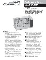
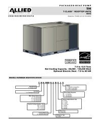
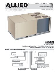
<strong>KGA</strong>024, 030, 036, 048, 060, 072, & KG 090 PARTS ARRANGEMENTFILTERS (4)024, 030, 036, 048,060:16 X 20 X 2"072, 090: 20 X 20 X 2"EVAPORATORCOILTXVBLOWERMOTORTB1 LOW VOLTAGETERMINAL BLOCKCONDENSERFANECONOMIZER(OPTIONAL)BLOWERCONDENSERCOILCONDENSATEDRAINCOMBUSTIONAIR INDUCERBURNERSGAS VALVECOMPRESSORKCA024, 030, 036, 048, 060, 072, & KC 090 PARTS ARRANGEMENTFILTERS (4)024, 030, 036, 048,060:16 X 20 X 2"072, 090: 20 X 20 X 2"EVAPORATORCOILTXVBLOWERMOTORTB1 LOW VOLTAGETERMINAL BLOCKCONDENSERFANECONOMIZER(OPTIONAL)BLOWERCONDENSERCOILCONDENSATEDRAINELECTRIC HEAT(Optional)COMPRESSORPage 3506001−01 4/2012
Shipping and Packing ListPackage 1 of 1 contains:1− Assembled unitCheck unit for shipping damage. Receiving party shouldcontact last carrier immediately if shipping damage is found.GeneralThese instructions are intended as a general guideand do not supersede local codes in any way.Authorities having jurisdiction should be consultedbefore installation.The KG units are available in three heating inputs. The KCcooling packaged rooftop unit is the same basic design asthe KG unit except for the heating section. Optional electricheat is available for KC units. KG and KC units have identicalrefrigerant circuits with respective 2, 2−1/2, 3, 4, 5 and 6 toncooling capacities. In addition, KG/KC units are available with7−1/2 tons of cooling.Availability of units and options varies by brand.RequirementsNOTICERoof Damage!This system contains both refrigerant and oil. Somerubber roofing material may absorb oil, causing therubber to swell. Bubbles in the rubber roofingmaterial can cause leaks. Protect the roof surfaceto avoid exposure to refrigerant and oil duringservice and installation. Failure to follow this noticecould result in damage to roof surface.WARNINGElectric shock hazard and danger ofexplosion. Can cause injury, death orproduct or property damage. Turn offgas and electrical power to unit beforeperforming any maintenance orservicing operations on the unit. Followlighting instructions attached to unitwhen putting unit back into operationand after service or maintenance.IMPORTANTThe Clean Air Act of 1990 bans the intentional ventingof refrigerant (CFC’s and HCFC’s) as of July 1,1992. Approved methods of recovery, recycling orreclaiming must be followed. Fines and/or incarcerationmay be levied for non−compliance.See figure 1 for unit clearances.<strong>KGA</strong>/KCA024, 030, 036, 048, 060, 072, 090Page 41 UnitClearanceServiceClearanceClearance toCombustiblesMinimum OperationClearanceDUNIT CLEARANCESAin.(mm)48*(1219)36(914)36(914)ACFIGURE 1Bin.(mm)36(914)1(25)36(914)Cin.(mm)36(914)1(25)36(914)BDin.(mm)36(914)1(25)36(914)TopClearanceUnobstructedUnobstructedUnobstructed*KC 090 unit A dimension is 36" (1219mm).Note − Entire perimeter of unit base requires support when elevated abovemounting surface.1 Service Clearance − Required for removal of serviceable parts.Clearance to Combustibles − Required clearance to combustible material(gas units).Minimum Operation Clearance − Required clearance for proper unit operation.Use of this unit as a construction heater or air conditioneris not recommended during any phase of construction.Very low return air temperatures, harmful vapors andoperation of the unit with clogged or misplaced filters willdamage the unit.If this unit has been used for heating or cooling ofbuildings or structures under construction, the followingconditions must be met or the warranty will be void: A room thermostat must control the unit. The use offixed jumpers that will provide continuous heating orcooling is not allowed. A pre−filter must be installed at the entry to the returnair duct. The return air duct must be provided and sealed tothe unit. Return air temperature range between 55°F (13°C)and 80°F (27°C) must be maintained. Air filters must be replaced and pre−filters must beremoved upon construction completion. The input rate and temperature rise must be set perthe unit rating plate. The heat exchanger, components, duct system, airfilters and evaporator coil must be thoroughlycleaned following final construction clean−up. The unit operating conditions (including airflow,cooling operation, ignition, input rate, temperaturerise and venting) must be verified according to theseinstallation instructions.
Unit SupportIn downflow discharge installations, install the unit on anon−combustible surface only. Unit may be installed oncombustible surfaces when used in horizontal dischargeapplications or in downflow discharge applications wheninstalled on a T1CURB or K1CURB roof mounting frame.KG/KC 024, 030, 036, 048, 060 and 072 units areinstalled on T1CURB frames. KG/KC 090 units areinstalled on K1CURB frames.NOTE − Securely fasten roof frame to roof per local codes.A−Downflow Discharge ApplicationRoof Mounting with T1CURB or K1CURB1− The T1CURB/K1CURB roof mounting frame must beinstalled, flashed and sealed in accordance with theinstructions provided with the frame.2− The T1CURB/K1CURB roof mounting frame shouldbe square and level to 1/16" per linear foot (5mm perlinear meter) in any direction.3− Duct must be attached to the roof mounting frameand not to the unit; supply and return plenums mustbe installed before setting the unit.Installer’s Roof Mounting FrameMany types of roof frames can be used to install the unitdepending upon different roof structures. Items to keepin mind when using the building frame or supports are:1− The base is fully enclosed and insulated, so anenclosed frame is not required.2− The frames or supports must be constructed withnon−combustible materials and should be square andlevel to 1/16" per linear foot (5mm per linear meter)in any direction.3− Frame or supports must be high enough to preventany form of moisture from entering unit.Recommended minimum frame height is 14"(356mm).4− Duct must be attached to the roof mounting frameand not to the unit. Supply and return plenums mustbe installed before setting the unit.5− Units require support along all four sides of unit base.Supports must be constructed of steel or suitablytreated wood materials.NOTE−When installing a unit on a combustible surface fordownflow discharge applications, a T1CURB/K1CURBroof mounting frame is required.B−Horizontal Discharge Applications1− Units which are equipped with an optionaleconomizer and installed in horizontal airflowapplications must use a horizontal conversion kit.2− Specified installation clearances must be maintainedwhen installing units. Refer to figure 1.Page 53− Top of support slab should be approximately 4"(102mm) above the finished grade and located so norun−off water from higher ground can collect aroundthe unit.4− Units require support along all four sides of unit base.Supports must be constructed of steel or suitablytreated wood materials.Duct ConnectionAll exterior ducts, joints and openings in roof or buildingwalls must be insulated and weather−proofed withflashing and sealing compounds in accordance withapplicable codes. Any duct passing through anunconditioned space must be insulated.CAUTIONIn downflow applications, do not drill or punchholes in base of unit. Leaking in roof may occur ifunit base is punctured.Rigging Unit For LiftingRig unit for lifting by attaching four cables to holes in unitbase rail. See figure 2.1− Detach wooden base protection before rigging.2− Remove all six base protection brackets beforesetting unit.3− Connect rigging to the unit base using both holes ineach corner.4− All panels must be in place for rigging.5− Place field-provided H-style pick in place just abovetop edge of unit. Frame must be of adequatestrength and length. (H−style pick prevents damageto unit.)RIGGINGKGKCUNIT*WEIGHTLBS.870820KG.395372*Maximum weight with all availableinstalled accessories.IMPORTANT − ALLPANELS MUST BE INPLACE FOR RIGGING.FIGURE 2LIFTING POINT SHOULDBE DIRECTLY ABOVECENTER OF GRAVITYCAUTION − Do notwalk on unit.506001−01 4/2012
Horizontal Air DischargeUnit is shipped with panels covering the horizontal supplyand return air openings. Remove horizontal covers andplace over downflow openings for horizontal air discharge.See figure 3. Secure in place with sheet metal screws.Units Equipped With An Optional Economizer1− Remove the horizontal supply air cover and positionover the downflow supply air opening. Secure withsheet metal screws.2− Leave the horizontal return air cover in place.3− Locate the separately ordered horizontal airdischarge kit. Place the kit panel over the downflowreturn air opening.4− Remove and retain the barometric relief dampers andlower hood.5− Install return air duct beneath outdoor air intake. Seefigure 4. Install barometric relief damper in lowerhood and install in ductwork as shown in figure 4.UNIT SUPPLY AND RETURN AIR OPENINGSHORIZONTALRETURN AIROPENINGHORIZONTALSUPPLY AIROPENINGCondensate DrainsMake drain connection to the drain coupling provided onunit. Older model units have a 3/4" N.P.T. coupling andnewer model units have a 1" N.P.T. coupling.Note − The drain pan is made with a glass reinforcedengineered plastic capable of withstanding typical jointtorque but can be damaged with excessive force. Tightenpipe nipple hand tight and turn an additional quarter turn.A trap must be installed between drain connection and anopen vent for proper condensate removal. See figure 5 or6. It is sometimes acceptable to drain condensate ontothe roof or grade; however, a tee should be fitted to thetrap to direct condensate downward. The condensate linemust be vented. Check local codes concerningcondensate disposal. Refer to pages 1 and 2 forcondensate drain location.CONDENSATE SIDE DRAIN CONNECTIONCAULK AROUND CONDENSATE COUPLINGNOTE − Allow clearance toopen doors when installingcondensate piping.Minimum Pitch1" (25 mm) per OPEN VENT10’ (3 m) of lineUNITMOUNTINGFRAMEÁDOWNFLOWRETURN AIROPENINGFIGURE 3DOWNFLOWSUPPLY AIROPENINGHORIZONTAL RETURN AIR DUCTWORKWITH ECONOMIZERUNITÁÁFIGURE 5CONDENSATE BOTTOM DRAIN CONNECTIONUNITÁDRAIN PANCAULK AROUNDCONDENSATE COUPLINGOPEN VENTHORIZONTALRETURN AIRDUCTINSTALL BAROMETRIC RELIEF DAMPERSAND HOOD IN RETURN AIR DUCTFIGURE 4MOUNTINGFRAMEMinimum Pitch1" (25 mm) per 10’(3 m) of lineFIGURE 6<strong>KGA</strong>/KCA024, 030, 036, 048, 060, 072, 090Page 6
Units are shipped with the drain coupling facing the frontof the unit. Condensate can be drained from the back orbottom of the unit with the following modifications. Theunit can be installed in either downflow or horizontal airdischarge regardless of condensate drain location.Rear Drain Connection1− Remove the condensate drain mullion. See figure 7.Remove the two panels on each side of the mullion.CONDENSATEDRAIN MULLION3− Make sure the cap over the unit bottom drain hole issecure.4− Rotate the drain pan until the downward slope istoward the back of the unit. Slide the drain pan backinto the unit. Be careful not to dislodge the cap overthe bottom drain hole.5− From the back side of the unit, pull the drain pancoupling through the rear condensate opening.6− Replace the condensate drain mullion.Bottom Drain Connection1− Remove the condensate drain mullion. See figure 7.2− Lift the front edge of the drain pan and slide pan outof unit. See figure 9.3− Turn the drain pan upside down and drill a pilot holethrough the bottom of the drain pan in the center of thecoupling. See figure 10.BOTTOM CONDENSATE DRAINFIGURE 7If the unit has hinged panels, two hinge screws mustbe removed in addition to the mullion screws. Seefigure 8.UNITS WITH HINGED PANELSCAUTION: Be careful not todamage the coupling threadswhen drilling the hole.DRILL A PILOTHOLE IN CENTEROF COUPLINGCONDENSATEDRAIN MULLIONFIGURE 8REMOVETWOSCREWS2− Lift the front edge of the drain pan and slide pan outof unit. See figure 9.REMOVE DRAIN PANDRAIN PANAfter drilling the pilothole, drill a 7/8" hole fromthe inside of the pan.FIGURE 104− From the inside of the pan, use a Vari−Bit ® bit toenlarge the hole to 7/8". Do not damage couplingthreads.5− Remove the cap over the unit bottom drain hole.6− Slide the drain pan back into the unit.7− From the back side of the unit, pull the drain pancoupling through the rear condensate opening.8− From the front side of the unit, move the drain panuntil the bottom coupling settles into the unit bottomdrain opening. Once in place, check to make sure thecoupling is still positioned through the rearcondensate drain hole.9− Use a field−provided 3/4" plug to seal side drainconnection.10− Replace the condensate drain mullion.FIGURE 9Page 7506001−01 4/2012
Connect Gas Piping (Gas Units)BOTTOM ENTRY GAS PIPING COMPLETEDBefore connecting field−provided piping, check with gascompany or authorities having jurisdiction for local coderequirements. When installing gas supply piping, lengthof run from gas meter must be considered in determiningpipe size for 0.5" w.c. (.12kPa) maximum pressure drop.Do not use supply pipe smaller than unit gas connection.Operating pressures at the unit gas connection must beas shown in table 1.TABLE 1OPERATING PRESSURE AT GAS CONNECTION w.c.STREETELBOW7" NIPPLEGROUNDJOINT UNIONTO GASVALVENatural Gas LP / Propane GasMin. Max. Min. Max.024−090 4.5 10.5 11 13When making piping connections a drip leg should beinstalled on vertical pipe runs to serve as a trap forsediment or condensate. A 1/8" N.P.T. plugged tap islocated on gas valve for test gauge connection. Refer toHeating Start−Up section for tap location. Install a groundjoint union between the gas control manifold and themain manual shut−off valve. See figure 11 for gas supplypiping entering outside the unit. Figure 12 showscomplete bottom gas entry piping.Compounds used on threaded joints of gas piping shall beresistant to the action of liquified petroleum gases.OUTSIDE OF UNIT GAS PIPE CONNECTIONTO GASSUPPLYGAS PIPINGSUPPORTGROUNDJOINT UNIONMANUAL MAINSHUT−OFF VALVEFIGURE 11DRIP LEGTO GASVALVE(REFER TOLOCAL CODES)<strong>KGA</strong>/KCA024, 030, 036, 048, 060, 072, 090Page 8TO GASSUPPLY2−1/2" NIPPLEMANUAL MAINSHUT−OFF VALVEDRIP LEGGrommets for both gas pipe openings are field provided.FIGURE 12Pressure Test Gas Piping (Gas Units)When pressure testing gas lines, the gas valve mustbe disconnected and isolated. Gas valves can bedamaged if subjected to more than 0.5 psig (3.48kPa).See figure 13.NOTE−Codes may require that manual main shut−off valveand union (furnished by installer) be installed in gas lineexternal to unit. Union must be of the ground joint type.After all connections have been made, check all pipingconnections for gas leaks. Also check existing unit gasconnections up to the gas valve; loosening may occurduring installation. Use a leak detection solution or otherpreferred means. Do not use matches candles or othersources of ignition to check for gas leaks.CAUTIONSome soaps used for leak detection are corrosiveto certain metals. Carefully rinse piping thoroughlyafter leak test has been completed. Do not usematches, candles, flame or othe sources of ignitionto check for gas leaks.WARNINGDanger of explosion. Can cause injuryor product or property damage. Do notuse matches, candles, flame or othersources of ignition to check for leaks.NOTE−In case emergency shut down is required, turn offthe main manual shut−off valve and disconnect mainpower to unit. These devices should be properly labeledby the installer.
MANUAL MAINSHUT−OFF VALVEGAS VALVEPRESSURE TEST GAS LINEHigh Altitude DerateFIGURE 13CAPLocate the high altitude conversion sticker in the unitliterature bag. Fill out the conversion sticker and affix nextto the unit nameplate.Refer to table 2 for high altitude adjustments.TABLE 2HIGH ALTITUDE DERATEAltitude Ft.*Gas Manifold Pressure2000−4500See Unit Nameplate4500 And Above Derate 2% / 1000 Ft. Above Sea Level*Units installed at 0−2000 feet do not need to be modified.NOTE - This is the only permissible derate for these units.Electrical ConnectionsLocate thermostat approximately 5 feet (1524mm)above the floor in an area with good air circulation ataverage temperature. Avoid locating the roomthermostat where it might be affected by:−drafts or dead spots behind doors and in corners−hot or cold air from ducts−radiant heat from sun or appliances−concealed pipes and chimneysB−Control Wiring1− Route thermostat cable or wires from subbase tocontrol area above compressor (refer to unitdimensions to locate bottom and side power entry).IMPORTANT − Unless field thermostat wires are rated formaximum unit voltage, they must be routed away fromline voltage wiring. Use wire ties located near the lowerleft corner of the controls hat section to securethermostat cable.Use18 AWG wire for all applications using remotelyinstalled electro−mechanical and electronicthermostats.2− Install thermostat assembly in accordance withinstructions provided with thermostat.3− Connect thermostat wiring to TB1 terminal board onthe lower side of the controls hat section. Wire asshown in figure 14 for electro−mechanical andelectronic thermostats. If using other temperaturecontrol devices or energy management systems seeinstructions and wiring diagram provided bymanufacturer.POWER SUPPLYDo not apply power or close disconnect switch untilinstallation is complete. Refer to start−up directions.Refer closely to unit wiring diagram.Refer to unit nameplate for minimum circuit ampacityand maximum fuse size.1− 1−Units are factory−wired for 230,460,575 volt supply.For 208V supply, remove the insulated terminal coverfrom the 208V terminal on the control transformer.Move the wire from the transformer 240V terminal tothe 208V terminal. Place the insulated terminal coveron the unused 240V terminal.2− Route power through the bottom power entry area.On KG units, connect power wiring to L1, L2 and L3on the top of K1 in control area above compressor.On KC units, route power wiring to TB2. Securepower wiring with factory−installed wire tiesprovided in control box. See unit wiring diagram.CONTROL WIRINGA−Thermostat LocationRoom thermostat mounts vertically on a standard 2" X 4"handy box or on any non−conductive flat surface.Page 924 VOLT FIELD WIRING WITH ELECTRONIC ANDELECTRO−MECHANICAL THERMOSTATSTB1A2 THERMOSTATFIGURE 14NOT ALL TERMINALSARE FOUND ON ALLTHERMOSTATSNote − On electro−mechanical thermostatsset anticipator at 0.1 amps.Jumper terminals R andOC when thermostat hasno night setback terminals.IMPORTANT−Terminal connections at the wall plate orsubbase must be made securely. Loose control wireconnections may allow unit to operate but not with properresponse to room demand.506001−01 4/2012
Blower Operation and Adjustments2 and 2−1/2 ton units are equipped with direct driveblowers only. 3, 4 and 5 ton units are equipped with eitherdirect drive or belt drive blowers. 6 and 7−1/2 ton units areavailable with belt drive blowers only.IMPORTANTThree phase scroll compressors must be phasedsequentially for correct compressor and blowerrotation. Follow COOLING START−UP" section ofinstallation instructions to ensure proper compressorand blower operation.A−Blower OperationInitiate blower demand at thermostat according toinstructions provided with thermostat. Unit will cycle onthermostat demand. The following steps apply toapplications using a typical electro−mechanicalthermostat.B−Determining Unit CFM − Direct Drive Blowers1− The following measurements must be made with airfilters in place.2− With all access panels in place, measure staticpressure external to unit (from supply to return). Addany additional air resistance for options andaccessories shown in table 18.3− Use figure 15 to determine the factory set blowerspeed.4− Use tables 4 through 6, the measured staticpressure and the factory−set blower speed todetermine CFM. If CFM is lower or higher than thedesign specified CFM, move the leads as shown infigure 16 for 208/230 volt units and figure 17 for460/575 volt units. Refer to table 21 or 22 forminimum airflow when electric heat is installed.036 UnitsBLOWER SPEED FACTORY SETTINGS024, 030, &048 Units 060 Units1− Blower operation is manually set at the thermostatsubbase fan switch. With fan switch in ON position,blowers will operate continuously.1234ComHiMedLow*1234ComHiMed*Low1234ComHiLow*Unused2− With fan switch in AUTO position, the blowers willcycle with demand. Blowers and entire unit will be offwhen system switch is in OFF position.*Factory SettingFIGURE 15FIELD−ADJUSTABLE BLOWER SPEEDS − DIRECT DRIVE 208/230VTERMINAL 1REMAINS ATCOMMONHIGH SPEED − ALL UNITSL1−Terminal COML2−Terminal HIGHLOW SPEED024, 030, 036, 048, UNITSL1−Terminal COML2−Terminal LOWMEDIUM SPEED024, 030, 036, 048 UNITSL1−Terminal COML2−Terminal MEDSPEEDTAPS1−COM2−HI3−MED4−LOW1−COM2−HI3−MED4−LOWLOW SPEED060 UNITSL1−Terminal COML2−Terminal LOW1−COM2−HI3−MED4−LOW1−COM2−HI3−LOW4−FIGURE 16<strong>KGA</strong>/KCA024, 030, 036, 048, 060, 072, 090Page 10
TAPE BACK AND SECUREUNUSED ISOLATION LEADTO CAPACITOR WIRES.Do not parkisolation leadFIELD−ADJUSTABLE BLOWER SPEEDSDIRECT DRIVE − 460/575VHIGH SPEEDL1−Terminal COML2−Terminal HILOW SPEED 036, 048 UNITSL1−Terminal COMPark isolation L2−Terminal LOWlead intoterminal HIMEDIUM SPEED 036, 048 UNITSL1−Terminal COML2−Terminal MEDPark isolationlead intoterminal HI1−COM2−HI3−MED4−LOW1−COM2−HI3−MED4−LOWPark isolationlead intoterminal HI1−COM2−HI3−LOW41−COM2−HI3−MED4−LOWLOW SPEED 060 UNITSL1−Terminal COML2−Terminal LOWFIGURE 17C−Determining Unit CFM − Belt Drive Blowers1− The following measurements must be made with airfilters in place.2− With all access panels in place, measure staticpressure external to unit (from supply to return).3− Measure the indoor blower wheel RPM.4− Referring to tables 7 through 17, use static pressureand RPM readings to determine unit CFM. Use table18 when installing units with any of the options oraccessories listed. Refer to table 21 or 22 forminimum airflow when electric heat is installed.5− The blower RPM can be adjusted at the motor pulley.Loosen Allen screw and turn adjustable pulleyclockwise to increase CFM. Turn counterclockwise todecrease CFM. See figure 19. Do not exceedminimum and maximum number of pulley turns asshown in table 3.D−Blower Belt AdjustmentMaximum life and wear can be obtained from belts onlyif proper pulley alignment and belt tension aremaintained. Tension new belts after a 24−48 hourperiod of operation. This will allow belt to stretch andseat grooves. Make sure blower and motor pulley arealigned as shown in figure 18.1− Loosen four bolts securing motor base to mountingframe. See figure 19.Page 112− To increase belt tension −Slide blower motor downward to tighten the belt. Thisincreases the distance between the blower motor andthe blower housing.3− To loosen belt tension −Slide blower motor upward to loosen the belt. Thisdecreases the distance between the blower motorand the blower housing.4− Tighten four bolts securing motor base to themounting frame.TABLE 3MINIMUM AND MAXIMUM PULLEY ADJUSTMENTBelt Min. Turns Open Maxi. Turns OpenA Section No minimum 5MOTORPULLEYPULLEY ALIGNMENTALIGNEDBELTNOT ALIGNEDFIGURE 18BLOWERPULLEY506001−01 4/2012
TO INCREASE CFMLOOSEN ALLEN SCREW &TURN PULLEY CLOCKWISETO DECREASE CFMTURN PULLEYCOUNTERCLOCKWISEBLOWER ASSEMBLYSIDE VIEWLOOSEN ALLENSCREW TOADJUST CFMMOTORALLENSCREWPULLEYTO INCREASE BELT TENSION1−Loosen four bolts securing motor base to mountingframe.2−Slide the motor downward to tighten the belt.3−Tighten four bolts on motor base.E−Blower Belt Adjustment − M Volt Units With 3 HPBlowers Equipped With A Belt Tensioner1− Remove blower belt.2− Remove bracket from blower housing. See figure 21.3− Remove the screw from the back side of the bracket.4− Move the tensioner to the appropriate adjustmenthole and reinstall screw.5− Replace bracket.6− Replace blower belt. See figure 22.F−Check Belt Tension − Units Not Equipped With ABelt TensionerOvertensioning belts shortens belt and bearing life.Check belt tension as follows:1− Measure span length X. See figure 20.2− Apply perpendicular force to center of span (X) withenough pressure to deflect belt 1/64" for every inchof span length or 1.5mm per 100mm of span length.Example: Deflection distance of a 40" span would be40/64" or 5/8".Example: Deflection distance of a 400mm spanwould be 6mm.LOOSEN FOUR BOLTS ANDSLIDE BLOWER MOTORDOWNWARD TO TIGHTEN BELTFIGURE 193− Measure belt deflection force. For a used belt, thedeflection force should be 5 lbs. (35kPa). A new beltdeflection force should be 7 lbs. (48kPa).A force below these values indicates anundertensioned belt. A force above these valuesindicates an overtensioned belt.G−Field−Furnished Blower DrivesFor field−furnished blower drives, use tables 7 through 17to determine BHP and RPM required. Reference table 19for drive component manufacturers numbers and table 20to determine the drive kit number.MEASURE BELT TENSIONFORCEDEFLECTION 1/64" PER INCH OF SPANOR 1.5mm PER 100mm OF SPANFIGURE 20<strong>KGA</strong>/KCA024, 030, 036, 048, 060, 072, 090Page 12
ADJUST BELT TENSIONERINSTALL BELTMAXIMUMTENSIONINDICATOR SHOULD BEBETWEEN MINIMUM ANDMAXIMUM TENSION LINES1TENSIONERDRIVERPULLEYMINIMUMTENSION2DRIVENPULLEYBRACKET3TENSIONERTIGHTESTBELTPOSITIONFACTORY−SETPOSITIONFIGURE 21TIGHTERBELTPOSITIONROTATE DRIVENPULLEY TO SEAT BELT4FIGURE 22Page 13506001−01 4/2012
External StaticPressure (in. w.g.)TABLE 4DIRECT DRIVE BLOWER PERFORMANCEAir Volume (cfm) at Various Blower Speeds208 VOLTS 230 VOLTSHigh Medium Low High Medium Low2 and 2.5 Ton Standard Efficiency (Down−Flow) <strong>KGA</strong>024S and <strong>KGA</strong>030S0.0 1255 985 860 1420 1150 9200.1 1240 965 830 1410 1120 9100.2 1225 940 790 1400 1095 8900.3 1210 910 745 1390 1065 8600.4 1185 870 695 1365 1030 8200.5 1150 825 − − − 1335 985 7700.6 1100 775 − − − 1280 935 7150.7 1035 715 − − − 1210 865 − − −0.8 940 − − − − − − 1115 780 − − −0.9 815 − − − − − − 990 − − − − − −1.0 − − − − − − − − − 830 − − − − − −2 and 2.5 Ton Standard Efficiency (Horizontal) <strong>KGA</strong>024S and <strong>KGA</strong>030S0.0 1190 935 815 1345 1090 8750.1 1175 915 785 1335 1065 8650.2 1160 890 750 1330 1035 8450.3 1145 860 705 1315 1010 8150.4 1125 825 660 1295 975 7750.5 1090 785 − − − 1265 935 7300.6 1045 735 − − − 1215 885 6750.7 980 680 − − − 1150 820 − − −0.8 890 − − − − − − 1055 740 − − −0.9 775 − − − − − − 935 − − − − − −1.0 − − − − − − − − − 785 − − − − − −2 and 2.5 Ton Standard Efficiency (Down−Flow) KCA024S and KCA030S0.0 1230 975 845 1425 1125 9100.1 1220 940 815 1395 1110 8750.2 1205 910 775 1375 1085 8450.3 1185 880 730 1350 1055 8150.4 1155 845 680 1320 1010 7800.5 1115 800 − − − 1280 955 7400.6 1060 750 − − − 1225 895 6900.7 985 685 − − − 1150 830 − − −0.8 890 − − − − − − 1050 755 − − −0.9 770 − − − − − − 920 680 − − −1.0 − − − − − − − − − 760 − − − − − −2 and 2.5 Ton Standard Efficiency (Horizontal) KCA024S and KCA030S0.0 1165 925 800 1350 1065 8650.1 1155 895 770 1325 1055 8300.2 1140 865 735 1300 1030 8000.3 1125 835 695 1280 1000 7700.4 1095 800 645 1250 955 7400.5 1055 760 − − − 1215 905 7000.6 1005 710 − − − 1160 850 6550.7 935 650 − − − 1090 785 − − −0.8 845 − − − − − − 995 720 − − −0.9 730 − − − − − − 875 645 − − −1.0 − − − − − − − − − 720 − − − − − −<strong>KGA</strong>/KCA024, 030, 036, 048, 060, 072, 090Page 14
External StaticPressure (in. w.g.)TABLE 6DIRECT DRIVE BLOWER PERFORMANCEAir Volume (cfm) at Various Blower Speeds208 VOLTS 230 VOLTS 460/575 VOLTSHigh Low High Low High Low5 Ton Standard Efficiency (Down−Flow) <strong>KGA</strong>060S0.0 2230 1670 2410 1950 2240 17300.1 2205 1680 2380 1945 2175 17250.2 2175 1685 2350 1930 2130 17250.3 2145 1685 2315 1915 2095 17250.4 2110 1670 2270 1890 2070 17200.5 2065 1650 2215 1860 2040 17050.6 2015 1615 2155 1815 2010 16750.7 1950 1565 2085 1755 1960 16300.8 1875 1495 2000 1685 1900 15600.9 1780 1410 1900 1595 1810 14651.0 1675 − − − 1785 − − − 1690 − − −5 Ton Standard Efficiency (Horizontal) <strong>KGA</strong>060S0.0 2110 1615 2280 1885 2305 18150.1 2075 1625 2245 1880 2260 18250.2 2040 1625 2205 1860 2215 18200.3 2000 1610 2155 1835 2170 18050.4 1950 1590 2100 1800 2120 17750.5 1900 1555 2040 1750 2065 17350.6 1835 1505 1965 1695 2005 16800.7 1765 1450 1890 1625 1935 16150.8 1685 1375 1800 1545 1855 15350.9 1595 1295 1700 1460 1755 14451.0 1495 − − − 1595 − − − 1645 − − −5 Ton Standard Efficiency (Down−Flow) KCA060S0.0 2140 1655 2315 1935 2155 17150.1 2110 1650 2280 1910 2085 16950.2 2080 1645 2245 1885 2035 16850.3 2045 1635 2205 1860 2000 16750.4 2005 1615 2160 1830 1970 16600.5 1965 1590 2105 1790 1940 16400.6 1910 1555 2045 1745 1905 16100.7 1845 1500 1970 1685 1855 15650.8 1765 1435 1885 1615 1790 14950.9 1675 1350 1785 1525 1700 14051.0 1565 − − − 1665 − − − 1580 − − −5 Ton Standard Efficiency (Horizontal) KCA060S0.0 2030 1600 2190 1870 2215 18000.1 1990 1595 2150 1850 2165 17960.2 1950 1585 2105 1820 2120 17800.3 1905 1565 2055 1780 2070 17500.4 1860 1535 2000 1735 2020 17150.5 1805 1495 1935 1685 1965 16700.6 1740 1450 1865 1625 1900 16150.7 1670 1390 1785 1560 1830 15500.8 1590 1320 1695 1485 1750 14750.9 1500 1240 1600 1400 1650 13851.0 1395 − − − 1485 − − − 1535 − − −<strong>KGA</strong>/KCA024, 030, 036, 048, 060, 072, 090Page 16
TABLE 7BELT DRIVE BLOWER PERFORMANCE0.10 to 0.80 in. w.g. 3 Ton Standard Efficiency (Down−Flow) <strong>KGA</strong>/KCA036SAirExternal Static (in.w.g.)Volume0.10 0.20 0.30 0.40 0.50 0.60 0.70 0.80(cfm)RPM BHP RPM BHP RPM BHP RPM BHP RPM BHP RPM BHP RPM BHP RPM BHPField Furnished Low Static − Drive Kit A01 Kit 5900 500 0.10 605 0.15 705 0.25 790 0.30 870 0.40 945 0.50 1010 0.60 1075 0.751000 535 0.15 630 0.20 720 0.25 805 0.35 885 0.45 955 0.55 1020 0.65 1085 0.801100 570 0.15 655 0.20 740 0.30 820 0.40 895 0.45 970 0.60 1035 0.70 1095 0.801200 605 0.20 685 0.25 765 0.35 840 0.40 915 0.50 980 0.60 1045 0.75 1110 0.851300 640 0.25 715 0.30 790 0.35 865 0.45 930 0.55 1000 0.65 1060 0.80 1120 0.901400 680 0.30 750 0.35 820 0.45 885 0.50 955 0.60 1015 0.70 1080 0.85 1135 0.951500 720 0.35 785 0.40 850 0.50 910 0.55 975 0.65 1035 0.80 1095 0.90 1155 1.050.90 to 1.60 in. w.g. 3 Ton Standard Efficiency (Down−Flow) <strong>KGA</strong>/KCA036SAirExternal Static (in.w.g.)Volume0.90 1.0 1.10 1.20 1.30 1.40 1.50 1.60(cfm)RPM BHP RPM BHP RPM BHP RPM BHP RPM BHP RPM BHP RPM BHP RPM BHPHigh Static − Drive Kit A05Field Furnished900 1135 0.85 1190 1.00 1245 1.10 1295 1.25 1345 1.40 1390 1.55 1435 1.70 1480 1.851000 1145 0.90 1200 1.05 1255 1.15 1305 1.30 1355 1.45 1400 1.60 1445 1.75 1490 1.901100 1155 0.95 1210 1.10 1265 1.20 1315 1.35 1365 1.50 1410 1.65 1455 1.80 1500 1.951200 1165 1.00 1225 1.15 1275 1.25 1325 1.40 1375 1.55 1425 1.75 1470 1.90 1510 2.051300 1180 1.05 1235 1.20 1285 1.30 1340 1.50 1385 1.65 1435 1.80 1480 1.95 1525 2.151400 1195 1.10 1245 1.25 1300 1.40 1350 1.55 1400 1.70 1445 1.85 1490 2.05 1535 2.201500 1210 1.15 1260 1.30 1315 1.45 1360 1.60 1410 1.75 1455 1.95 1500 2.10 1545 2.300.10 to 0.80 in. w.g. 3 Ton Standard Efficiency (Horizontal) <strong>KGA</strong>/KCA036SAirExternal Static (in.w.g.)Volume0.10 0.20 0.30 0.40 0.50 0.60 0.70 0.80(cfm)RPM BHP RPM BHP RPM BHP RPM BHP RPM BHP RPM BHP RPM BHP RPM BHPField FurnishedLow Static − Drive Kit A01900 490 0.10 580 0.15 665 0.20 745 0.25 815 0.30 880 0.40 940 0.45 1000 0.551000 525 0.10 610 0.15 690 0.25 760 0.30 830 0.35 895 0.45 955 0.50 1010 0.601100 560 0.15 640 0.20 710 0.25 780 0.30 850 0.40 910 0.45 970 0.55 1025 0.651200 600 0.20 670 0.25 740 0.30 805 0.35 870 0.45 930 0.50 985 0.60 1040 0.701300 635 0.25 705 0.30 770 0.35 830 0.40 890 0.50 950 0.55 1005 0.65 1055 0.751400 675 0.30 740 0.35 800 0.40 860 0.50 915 0.55 970 0.65 1025 0.70 1075 0.801500 715 0.35 775 0.40 830 0.45 885 0.55 940 0.60 995 0.70 1045 0.80 1095 0.900.90 to 1.60 in. w.g. 3 Ton Standard Efficiency (Horizontal) <strong>KGA</strong>/KCA036SAirExternal Static (in.w.g.)Volume0.90 1.0 1.10 1.20 1.30 1.40 1.50 1.60(cfm)RPM BHP RPM BHP RPM BHP RPM BHP RPM BHP RPM BHP RPM BHP RPM BHPHigh Static − Drive Kit A05Field900 1055 0.60 1105 0.70 1155 0.80 1205 0.90 1250 0.95 1295 1.05 1335 1.15 1375 1.251000 1065 0.65 1115 0.75 1165 0.85 1215 0.95 1260 1.05 1305 1.15 1345 1.20 1385 1.301100 1080 0.70 1130 0.80 1175 0.90 1225 1.00 1270 1.10 1315 1.20 1355 1.30 1395 1.401200 1090 0.75 1140 0.85 1190 0.95 1235 1.05 1280 1.15 1325 1.25 1365 1.35 1405 1.451300 1105 0.80 1155 0.90 1205 1.00 1250 1.10 1295 1.25 1335 1.35 1375 1.45 1415 1.551400 1125 0.90 1170 1.00 1220 1.10 1265 1.20 1305 1.30 1350 1.40 1390 1.50 1430 1.651500 1145 1.00 1190 1.05 1235 1.15 1280 1.30 1320 1.40 1365 1.50 1405 1.60 1440 1.70Page 17506001−01 4/2012
TABLE 8BELT DRIVE BLOWER PERFORMANCE0.10 to 0.80 in. w.g. 4 Ton Standard Efficiency (Down−Flow) <strong>KGA</strong>/KCA048SAirVolume(cfm)External Static (in.w.g.)0.10 0.20 0.30 0.40 0.50 0.60 0.70 0.80RPM BHP RPM BHP RPM BHP RPM BHP RPM BHP RPM BHP RPM BHP RPM BHPField FurnishedLow Static − Drive Kit A021200 600 0.20 680 0.25 755 0.30 830 0.35 900 0.45 965 0.55 1025 0.65 1085 0.751300 640 0.20 710 0.25 780 0.35 850 0.40 915 0.50 980 0.60 1040 0.70 1100 0.801400 675 0.25 745 0.30 810 0.40 875 0.45 940 0.55 1000 0.65 1060 0.75 1115 0.851500 715 0.30 780 0.35 840 0.45 900 0.50 960 0.60 1020 0.70 1080 0.80 1135 0.901600 755 0.35 815 0.45 870 0.50 930 0.60 985 0.65 1045 0.75 1100 0.85 1150 0.951700 795 0.45 850 0.50 905 0.55 960 0.65 1015 0.75 1070 0.85 1120 0.95 1170 1.051800 835 0.50 885 0.60 940 0.65 990 0.75 1045 0.80 1095 0.90 1145 1.00 1195 1.151900 880 0.60 925 0.65 975 0.75 1025 0.80 1075 0.90 1120 1.00 1170 1.10 1220 1.202000 920 0.70 965 0.75 1010 0.85 1055 0.90 1105 1.00 1150 1.10 1195 1.20 1245 1.350.90 to 1.60 in. w.g. 4 Ton Standard Efficiency (Down−Flow) <strong>KGA</strong>/KCA048SAirExternal Static (in.w.g.)Volume 0.90 1.00 1.10 1.20 1.30 1.40 1.50 1.60(cfm) RPM BHP RPM BHP RPM BHP RPM BHP RPM BHP RPM BHP RPM BHP RPM BHPHigh Static − Drive Kit A06Field1200 1140 0.85 1195 0.95 1245 1.05 1295 1.20 1340 1.30 1385 1.40 1430 1.55 1470 1.651300 1155 0.90 1205 1.00 1260 1.10 1305 1.25 1350 1.35 1395 1.50 1440 1.60 1480 1.751400 1170 0.95 1220 1.05 1270 1.15 1320 1.30 1365 1.40 1410 1.55 1455 1.70 1495 1.801500 1185 1.00 1235 1.10 1285 1.25 1335 1.35 1380 1.50 1425 1.65 1465 1.75 1510 1.901600 1205 1.10 1255 1.20 1300 1.30 1350 1.45 1395 1.60 1435 1.70 1480 1.85 1520 2.001700 1220 1.15 1270 1.25 1320 1.40 1365 1.55 1410 1.65 1450 1.80 1495 1.95 1535 2.051800 1245 1.25 1290 1.35 1335 1.50 1380 1.60 1425 1.75 1465 1.90 1510 2.05 1550 2.151900 1265 1.35 1310 1.45 1355 1.60 1400 1.70 1440 1.85 1485 2.00 1525 2.15 1565 2.302000 1290 1.45 1330 1.55 1375 1.70 1420 1.80 1460 1.95 1500 2.10 1540 2.25 1580 2.400.10 to 0.80 in. w.g. 4 Ton Standard Efficiency (Horizontal) <strong>KGA</strong>/KCA048SAirVolume(cfm)External Static (in.w.g.)0.10 0.20 0.30 0.40 0.50 0.60 0.70 0.80RPM BHP RPM BHP RPM BHP RPM BHP RPM BHP RPM BHP RPM BHP RPM BHPField FurnishedLow Static − Drive Kit A021200 590 0.20 665 0.25 735 0.30 805 0.35 870 0.40 930 0.50 990 0.55 1050 0.651300 630 0.20 695 0.25 760 0.35 825 0.40 890 0.45 950 0.55 1010 0.65 1065 0.701400 670 0.25 730 0.30 790 0.40 850 0.45 910 0.50 970 0.60 1025 0.70 1080 0.751500 710 0.35 765 0.40 820 0.45 880 0.50 935 0.60 990 0.65 1045 0.75 1095 0.851600 750 0.40 800 0.45 855 0.50 910 0.60 960 0.65 1015 0.75 1065 0.80 1115 0.901700 790 0.45 840 0.50 890 0.60 940 0.65 990 0.75 1040 0.80 1090 0.90 1135 1.001800 830 0.55 875 0.60 925 0.65 970 0.75 1020 0.80 1065 0.90 1115 1.00 1160 1.101900 870 0.65 915 0.70 960 0.75 1005 0.85 1050 0.90 1095 1.00 1140 1.10 1185 1.202000 915 0.75 955 0.80 995 0.85 1040 0.95 1080 1.00 1125 1.10 1165 1.20 1210 1.300.90 to 1.60 in. w.g. 4 Ton Standard Efficiency (Horizontal) <strong>KGA</strong>/KCA048SAirExternal Static (in.w.g.)Volume 0.90 1.0 1.10 1.20 1.30 1.40 1.50 1.60(cfm) RPM BHP RPM BHP RPM BHP RPM BHP RPM BHP RPM BHP RPM BHP RPM BHPKit A02 High Static − Drive Kit A061200 1105 0.75 1155 0.85 1205 0.95 1255 1.05 1300 1.15 1340 1.25 1385 1.35 1425 1.451300 1115 0.80 1165 0.90 1215 1.00 1265 1.10 1310 1.20 1355 1.30 1395 1.40 1435 1.551400 1130 0.85 1180 0.95 1230 1.05 1275 1.15 1320 1.25 1365 1.40 1405 1.50 1450 1.601500 1145 0.90 1195 1.00 1245 1.15 1290 1.25 1335 1.35 1375 1.45 1420 1.55 1460 1.701600 1165 1.00 1210 1.10 1260 1.20 1305 1.30 1345 1.40 1390 1.55 1430 1.65 1470 1.751700 1185 1.10 1230 1.20 1275 1.30 1320 1.40 1360 1.50 1405 1.60 1445 1.75 1485 1.851800 1205 1.15 1250 1.25 1295 1.40 1335 1.50 1380 1.60 1420 1.70 1460 1.85 1500 1.951900 1225 1.25 1270 1.35 1315 1.50 1355 1.60 1395 1.70 1435 1.80 1475 1.95 1515 2.102000 1250 1.40 1295 1.50 1335 1.60 1375 1.70 1415 1.80 1455 1.95 1490 2.05 1530 2.20<strong>KGA</strong>/KCA024, 030, 036, 048, 060, 072, 090Page 18
TABLE 9BELT DRIVE BLOWER PERFORMANCE0.10 to 0.80 in. w.g. 5 Ton Standard Efficiency (Down−Flow) <strong>KGA</strong>/KCA060SAirVolume(cfm)External Static (in.w.g.)0.10 0.20 0.30 0.40 0.50 0.60 0.70 0.80RPM BHP RPM BHP RPM BHP RPM BHP RPM BHP RPM BHP RPM BHP RPM BHPField FurnishedLow Static − Drive Kit A031600 765 0.35 820 0.40 870 0.45 925 0.55 975 0.60 1025 0.65 1075 0.70 1120 0.801700 805 0.45 855 0.50 905 0.55 955 0.60 1005 0.65 1055 0.75 1100 0.80 1145 0.851800 850 0.50 895 0.55 945 0.60 990 0.70 1035 0.75 1080 0.80 1125 0.90 1170 0.951900 890 0.60 935 0.65 980 0.70 1025 0.75 1070 0.85 1115 0.90 1155 1.00 1200 1.052000 935 0.70 975 0.75 1020 0.80 1060 0.85 1100 0.95 1145 1.00 1185 1.10 1225 1.152100 975 0.80 1015 0.85 1055 0.90 1095 0.95 1135 1.05 1175 1.10 1215 1.20 1255 1.252200 1020 0.90 1055 0.95 1095 1.00 1135 1.10 1170 1.15 1210 1.25 1250 1.30 1285 1.402300 1060 1.00 1095 1.10 1135 1.15 1170 1.20 1210 1.30 1245 1.35 1280 1.45 1320 1.552400 1105 1.15 1140 1.20 1175 1.30 1210 1.35 1245 1.45 1280 1.50 1315 1.60 1350 1.700.90 to 1.60 in. w.g. 5 Ton Standard Efficiency (Down−Flow) <strong>KGA</strong>/KCA060SAirVolume(cfm)External Static (in.w.g.)0.90 1.00 1.10 1.20 1.30 1.40 1.50 1.60RPM BHP RPM BHP RPM BHP RPM BHP RPM BHP RPM BHP RPM BHP RPM BHPDrive Kit A03High Static − Drive Kit A071600 1165 0.85 1210 0.95 1255 1.05 1295 1.10 1335 1.20 1375 1.30 1415 1.35 1450 1.451700 1190 0.95 1235 1.05 1275 1.10 1315 1.20 1355 1.30 1395 1.35 1430 1.45 1470 1.551800 1215 1.05 1255 1.10 1295 1.20 1335 1.30 1375 1.40 1415 1.45 1450 1.55 1485 1.651900 1240 1.15 1280 1.20 1320 1.30 1360 1.40 1395 1.50 1435 1.60 1470 1.65 1505 1.752000 1265 1.25 1305 1.30 1345 1.40 1380 1.50 1420 1.60 1455 1.70 1490 1.80 1525 1.902100 1295 1.35 1335 1.45 1370 1.55 1405 1.60 1445 1.70 1480 1.80 1515 1.90 1550 2.002200 1325 1.50 1360 1.55 1395 1.65 1435 1.75 1470 1.85 1505 1.95 1535 2.05 1570 2.152300 1355 1.60 1390 1.70 1425 1.80 1460 1.90 1495 2.00 1530 2.10 1560 2.20 1595 2.302400 1385 1.75 1420 1.85 1455 1.95 1490 2.05 1520 2.15 1555 2.25 1585 2.35 1620 2.450.10 to 0.80 in. w.g. 5 Ton Standard Efficiency (Horizontal) <strong>KGA</strong>/KCA060SAirVolume(cfm)External Static (in.w.g.)0.10 0.20 0.30 0.40 0.50 0.60 0.70 0.80RPM BHP RPM BHP RPM BHP RPM BHP RPM BHP RPM BHP RPM BHP RPM BHPField FurnishedLow Static − Drive Kit A031600 750 0.35 805 0.40 865 0.50 925 0.55 980 0.65 1040 0.75 1095 0.85 1150 0.951700 790 0.45 845 0.50 900 0.55 955 0.65 1010 0.75 1065 0.80 1115 0.90 1170 1.051800 830 0.50 880 0.55 930 0.65 985 0.70 1035 0.80 1090 0.90 1140 1.00 1190 1.101900 870 0.60 920 0.65 965 0.75 1015 0.80 1065 0.90 1115 1.00 1165 1.10 1210 1.202000 910 0.70 955 0.75 1005 0.85 1050 0.90 1095 1.00 1145 1.10 1190 1.20 1235 1.302100 955 0.80 995 0.85 1040 0.95 1085 1.00 1130 1.10 1175 1.20 1220 1.30 1260 1.402200 995 0.90 1035 0.95 1075 1.05 1120 1.15 1160 1.20 1205 1.30 1245 1.40 1290 1.552300 1035 1.00 1075 1.10 1115 1.15 1155 1.25 1195 1.35 1235 1.45 1275 1.55 1320 1.652400 1080 1.15 1115 1.25 1155 1.30 1190 1.40 1230 1.50 1270 1.60 1310 1.70 1345 1.800.90 to 1.60 in. w.g. 5 Ton Standard Efficiency (Horizontal) <strong>KGA</strong>/KCA060SAirVolume(cfm)External Static (in.w.g.)0.90 1.00 1.10 1.20 1.30 1.40 1.50 1.60RPM BHP RPM BHP RPM BHP RPM BHP RPM BHP RPM BHP RPM BHP RPM BHPDrive Kit High Static − Drive Kit A07A031600 1200 1.05 1250 1.20 1300 1.30 1350 1.45 1395 1.55 1440 1.70 1485 1.85 1525 2.001700 1220 1.15 1270 1.25 1315 1.40 1365 1.50 1410 1.65 1455 1.80 1495 1.90 1540 2.101800 1240 1.20 1285 1.35 1335 1.45 1380 1.60 1425 1.75 1470 1.90 1510 2.00 1550 2.151900 1260 1.30 1305 1.45 1350 1.55 1395 1.70 1440 1.85 1485 1.95 1525 2.10 1565 2.252000 1280 1.40 1325 1.55 1370 1.65 1415 1.80 1455 1.90 1500 2.05 1540 2.20 1580 2.352100 1305 1.50 1350 1.65 1390 1.75 1435 1.90 1475 2.05 1515 2.20 1555 2.30 1595 2.502200 1330 1.65 1375 1.75 1415 1.90 1455 2.00 1495 2.15 1535 2.30 1575 2.45 1615 2.602300 1360 1.80 1400 1.90 1440 2.05 1480 2.15 1515 2.30 1555 2.45 1595 2.60 1630 2.752400 1385 1.90 1425 2.05 1465 2.20 1500 2.30 1540 2.45 1580 2.60 1615 2.75 1650 2.90Page 19506001−01 4/2012
BLOWER DATA - BELT DRIVE - DOWNFLOW - <strong>KGA</strong>072BLOWER TABLE INCLUDES RESISTANCE FOR BASE UNIT ONLY WITH DRY INDOOR COIL AND AIR FILTERS IN PLACE.FOR ALL UNITS ADD:1 - Any factory installed options air resistance (heat section, economizer, wet coil, etc.).2 - Any field installed accessories air resistance (duct resistance, diffuser, etc.).See page 28 for blower motors and drives and wet coil and options/accessory air resistance data.External Static - in. w.g.Air 0.10 0.20 0.30 0.40 0.50 0.60 0.70 0.80Volumecfm RPM BHP RPM BHP RPM BHP RPM BHP RPM BHP RPM BHP RPM BHP RPM BHPField FurnishedKit A041900 857 0.41 892 0.45 927 0.50 962 0.55 999 0.60 1036 0.65 1074 0.69 1112 0.732000 879 0.47 913 0.52 948 0.56 984 0.61 1020 0.67 1058 0.72 1096 0.76 1134 0.802100 900 0.53 935 0.58 970 0.63 1007 0.69 1044 0.74 1081 0.79 1119 0.84 1157 0.882200 922 0.60 958 0.65 994 0.71 1031 0.76 1068 0.82 1106 0.87 1143 0.91 1180 0.952300 947 0.67 983 0.73 1020 0.79 1057 0.85 1094 0.90 1131 0.95 1168 1.00 1205 1.032400 974 0.76 1010 0.82 1047 0.88 1084 0.94 1120 0.99 1157 1.04 1193 1.08 1230 1.122500 1002 0.85 1039 0.91 1075 0.97 1112 1.03 1148 1.08 1184 1.13 1220 1.17 1257 1.212600 1032 0.95 1068 1.01 1105 1.07 1141 1.13 1177 1.17 1213 1.22 1248 1.26 1284 1.312700 1062 1.05 1099 1.11 1136 1.17 1172 1.22 1207 1.27 1242 1.32 1277 1.37 1312 1.432800 1094 1.16 1131 1.22 1167 1.27 1202 1.32 1237 1.38 1271 1.43 1305 1.49 1339 1.562900 1127 1.26 1163 1.32 1198 1.38 1233 1.44 1267 1.50 1300 1.56 1334 1.64 1367 1.71External Static - in. w.g.Air 0.90 1.00 1.10 1.20 1.30 1.40 1.50 1.60Volumecfm RPM BHP RPM BHP RPM BHP RPM BHP RPM BHP RPM BHP RPM BHP RPM BHPKit A04Kit A081900 1150 0.77 1188 0.81 1227 0.85 1267 0.88 1303 0.92 1333 0.97 1360 1.02 1392 1.062000 1172 0.84 1210 0.88 1248 0.92 1286 0.96 1321 1.00 1350 1.05 1377 1.10 1409 1.142100 1195 0.91 1233 0.95 1269 1.00 1306 1.04 1339 1.09 1367 1.14 1395 1.19 1426 1.232200 1218 0.99 1255 1.03 1290 1.09 1324 1.14 1356 1.19 1385 1.24 1413 1.28 1444 1.322300 1242 1.07 1277 1.13 1310 1.20 1343 1.26 1374 1.30 1403 1.34 1432 1.38 1464 1.422400 1267 1.16 1300 1.23 1332 1.31 1364 1.37 1394 1.41 1423 1.45 1453 1.48 1484 1.532500 1292 1.26 1324 1.34 1355 1.42 1387 1.48 1417 1.52 1445 1.56 1475 1.59 1506 1.642600 1318 1.38 1350 1.46 1380 1.55 1411 1.60 1440 1.64 1469 1.68 1498 1.71 1529 1.762700 1345 1.51 1376 1.60 1406 1.68 1436 1.73 1465 1.77 1493 1.80 1523 1.84 1553 1.882800 1372 1.65 1403 1.74 1433 1.82 1462 1.86 1490 1.90 1519 1.93 1548 1.97 1578 2.012900 1399 1.80 1430 1.89 1460 1.96 1489 2.00 1516 2.03 1544 2.06 1573 2.10 1603 2.14Page 20
BLOWER DATA - BELT DRIVE - HORIZONTAL - <strong>KGA</strong>072BLOWER TABLE INCLUDES RESISTANCE FOR BASE UNIT ONLY WITH DRY INDOOR COIL AND AIR FILTERS IN PLACE.FOR ALL UNITS ADD:1 - Any factory installed options air resistance (heat section, economizer, wet coil, etc.).2 - Any field installed accessories air resistance (duct resistance, diffuser, etc.).See page 28 for blower motors and drives and wet coil and options/accessory air resistance data.External Static - in. w.g.Air 0.10 0.20 0.30 0.40 0.50 0.60 0.70 0.80Volumecfm RPM BHP RPM BHP RPM BHP RPM BHP RPM BHP RPM BHP RPM BHP RPM BHPField FurnishedKit A041900 796 0.38 837 0.43 878 0.48 918 0.53 958 0.58 997 0.62 1036 0.67 1074 0.712000 833 0.43 870 0.48 907 0.54 943 0.59 980 0.64 1018 0.69 1055 0.73 1093 0.772100 864 0.50 897 0.55 931 0.60 966 0.65 1002 0.71 1038 0.76 1075 0.80 1113 0.832200 887 0.57 920 0.62 953 0.67 988 0.73 1024 0.78 1060 0.83 1097 0.87 1135 0.902300 909 0.64 942 0.70 976 0.75 1011 0.81 1046 0.86 1083 0.91 1120 0.95 1157 0.982400 931 0.72 965 0.78 999 0.83 1035 0.89 1071 0.94 1108 0.99 1144 1.03 1181 1.072500 955 0.80 989 0.86 1024 0.92 1061 0.98 1097 1.03 1133 1.08 1170 1.11 1205 1.152600 981 0.90 1016 0.96 1052 1.01 1088 1.07 1124 1.12 1160 1.16 1195 1.20 1230 1.252700 1009 0.99 1044 1.05 1080 1.11 1116 1.16 1152 1.21 1187 1.26 1221 1.30 1254 1.352800 1038 1.10 1073 1.16 1109 1.21 1145 1.26 1180 1.31 1214 1.36 1247 1.40 1279 1.462900 1068 1.20 1104 1.26 1139 1.31 1174 1.36 1208 1.41 1240 1.47 1273 1.52 1304 1.58External Static - in. w.g.Air 0.90 1.00 1.10 1.20 1.30 1.40 1.50 1.60Volumecfm RPM BHP RPM BHP RPM BHP RPM BHP RPM BHP RPM BHP RPM BHP RPM BHPKit A04Kit A081900 1112 0.74 1151 0.77 1190 0.81 1228 0.84 1265 0.88 1301 0.92 1335 0.97 1367 1.012000 1131 0.80 1170 0.83 1208 0.87 1245 0.91 1281 0.96 1316 1.00 1349 1.04 1380 1.092100 1151 0.87 1189 0.90 1227 0.94 1263 0.99 1298 1.04 1331 1.08 1363 1.13 1394 1.172200 1173 0.94 1210 0.98 1246 1.02 1281 1.07 1315 1.12 1347 1.17 1379 1.22 1409 1.262300 1195 1.02 1231 1.06 1266 1.11 1300 1.16 1333 1.22 1364 1.27 1395 1.32 1424 1.362400 1217 1.10 1252 1.15 1286 1.20 1319 1.26 1351 1.32 1382 1.38 1411 1.43 1440 1.482500 1240 1.20 1274 1.25 1307 1.31 1339 1.37 1370 1.43 1400 1.49 1428 1.55 1457 1.592600 1264 1.30 1297 1.35 1329 1.42 1360 1.49 1389 1.55 1418 1.61 1446 1.67 1475 1.722700 1287 1.40 1319 1.47 1350 1.54 1380 1.61 1409 1.68 1437 1.74 1465 1.79 1493 1.842800 1311 1.52 1342 1.59 1373 1.66 1402 1.74 1430 1.8 1457 1.87 1485 1.92 1513 1.972900 1335 1.65 1366 1.72 1395 1.79 1424 1.87 1451 1.94 1478 2.00 1505 2.05 1533 2.09Page 21
BLOWER DATA - BELT DRIVE - KCA072 - DOWNFLOWBLOWER TABLE INCLUDES RESISTANCE FOR BASE UNIT ONLY WITH DRY INDOOR COIL AND AIR FILTERS IN PLACE.FOR ALL UNITS ADD:1 - Any factory installed options air resistance (heat section, economizer, wet coil, etc.).2 - Any field installed accessories air resistance (duct resistance, diffuser, etc.).See page 28 for blower motors and drives and wet coil and options/accessory air resistance data.External Static - in. w.g.Air 0.10 0.20 0.30 0.40 0.50 0.60 0.70 0.80Volumecfm RPM BHP RPM BHP RPM BHP RPM BHP RPM BHP RPM BHP RPM BHP RPM BHPField FurnishedDrive Kit A041900 826 0.36 859 0.41 894 0.45 928 0.50 964 0.56 1000 0.61 1036 0.66 1072 0.702000 857 0.42 889 0.47 920 0.52 952 0.57 986 0.62 1020 0.68 1055 0.73 1091 0.772100 878 0.49 909 0.54 940 0.59 973 0.64 1006 0.70 1041 0.75 1076 0.80 1112 0.852200 897 0.55 929 0.61 961 0.66 994 0.72 1028 0.78 1063 0.83 1099 0.89 1134 0.932300 918 0.62 950 0.68 983 0.74 1017 0.80 1052 0.86 1087 0.92 1122 0.97 1157 1.022400 941 0.70 974 0.77 1008 0.83 1042 0.90 1077 0.96 1111 1.01 1146 1.06 1181 1.112500 966 0.79 1000 0.86 1034 0.93 1068 1.00 1103 1.06 1137 1.11 1171 1.16 1205 1.202600 994 0.90 1028 0.97 1062 1.04 1096 1.10 1130 1.16 1164 1.21 1197 1.26 1231 1.302700 1023 1.01 1057 1.08 1091 1.15 1125 1.22 1159 1.27 1192 1.32 1225 1.37 1258 1.412800 1053 1.13 1088 1.21 1122 1.27 1155 1.33 1188 1.39 1221 1.43 1253 1.48 1286 1.532900 1085 1.26 1119 1.33 1153 1.40 1186 1.45 1218 1.51 1250 1.55 1281 1.61 1313 1.66External Static - in. w.g.Air 0.90 1.00 1.10 1.20 1.30 1.40 1.50 1.60Volumecfm RPM BHP RPM BHP RPM BHP RPM BHP RPM BHP RPM BHP RPM BHP RPM BHPDrive Kit A04Kit A081900 1109 0.75 1146 0.79 1183 0.82 1221 0.86 1260 0.90 1294 0.94 1323 0.98 1349 1.022000 1128 0.82 1164 0.86 1201 0.89 1239 0.93 1276 0.97 1310 1.01 1336 1.06 1362 1.102100 1148 0.89 1185 0.93 1221 0.97 1258 1.01 1294 1.05 1325 1.09 1351 1.14 1376 1.192200 1170 0.97 1206 1.01 1242 1.05 1277 1.09 1311 1.14 1341 1.18 1365 1.23 1390 1.282300 1193 1.06 1228 1.09 1262 1.14 1295 1.19 1327 1.24 1355 1.29 1380 1.33 1406 1.372400 1216 1.15 1250 1.19 1282 1.24 1313 1.30 1343 1.36 1371 1.40 1396 1.44 1423 1.482500 1240 1.24 1273 1.29 1302 1.36 1331 1.42 1360 1.48 1388 1.52 1414 1.55 1441 1.582600 1265 1.34 1296 1.40 1324 1.47 1352 1.54 1381 1.60 1408 1.64 1434 1.67 1460 1.702700 1291 1.46 1321 1.52 1347 1.60 1374 1.67 1403 1.72 1429 1.76 1455 1.79 1481 1.822800 1317 1.58 1346 1.66 1372 1.74 1399 1.80 1426 1.85 1451 1.89 1477 1.92 1503 1.952900 1343 1.72 1371 1.80 1397 1.88 1424 1.95 1450 1.99 1475 2.02 1500 2.05 1526 2.08Page 22
BLOWER DATA - BELT DRIVE - KCA072 - HORIZONTALBLOWER TABLE INCLUDES RESISTANCE FOR BASE UNIT ONLY WITH DRY INDOOR COIL AND AIR FILTERS IN PLACE.FOR ALL UNITS ADD:1 - Any factory installed options air resistance (heat section, economizer, wet coil, etc.).2 - Any field installed accessories air resistance (duct resistance, diffuser, etc.).See page 28 for blower motors and drives and wet coil and options/accessory air resistance data.External Static - in. w.g.Air 0.10 0.20 0.30 0.40 0.50 0.60 0.70 0.80Volumecfm RPM BHP RPM BHP RPM BHP RPM BHP RPM BHP RPM BHP RPM BHP RPM BHPField FurnishedDrive Kit A041900 853 0.41 886 0.46 919 0.50 952 0.55 986 0.60 1021 0.64 1056 0.69 1091 0.732000 883 0.48 913 0.53 944 0.57 976 0.62 1009 0.67 1043 0.71 1078 0.76 1112 0.802100 906 0.56 936 0.60 967 0.65 999 0.70 1033 0.75 1067 0.79 1101 0.84 1135 0.882200 930 0.64 960 0.68 991 0.73 1024 0.78 1058 0.83 1092 0.88 1126 0.92 1160 0.962300 954 0.72 985 0.77 1017 0.82 1051 0.87 1085 0.92 1119 0.96 1152 1.00 1186 1.042400 981 0.81 1013 0.86 1046 0.91 1079 0.96 1113 1.00 1146 1.05 1180 1.09 1213 1.132500 1010 0.91 1042 0.96 1075 1.00 1109 1.05 1142 1.09 1175 1.14 1207 1.18 1239 1.232600 1040 1.01 1073 1.05 1106 1.10 1139 1.14 1171 1.19 1203 1.23 1235 1.28 1266 1.332700 1072 1.10 1104 1.15 1137 1.20 1169 1.24 1201 1.29 1232 1.34 1263 1.40 1293 1.462800 1105 1.21 1137 1.25 1168 1.30 1200 1.35 1231 1.40 1261 1.46 1291 1.52 1321 1.592900 1138 1.32 1169 1.37 1200 1.42 1231 1.47 1261 1.53 1291 1.60 1321 1.66 1350 1.73External Static - in. w.g.Air 0.90 1.00 1.10 1.20 1.30 1.40 1.50 1.60Volumecfm RPM BHP RPM BHP RPM BHP RPM BHP RPM BHP RPM BHP RPM BHP RPM BHPDrive Kit A04Kit A081900 1126 0.77 1163 0.81 1200 0.85 1237 0.88 1273 0.92 1306 0.96 1339 1.00 1371 1.042000 1148 0.84 1183 0.88 1220 0.92 1257 0.96 1291 1.00 1323 1.04 1354 1.08 1385 1.122100 1170 0.92 1206 0.96 1242 1.00 1277 1.04 1310 1.08 1340 1.13 1371 1.17 1401 1.212200 1195 1.00 1230 1.04 1265 1.08 1299 1.13 1330 1.18 1359 1.23 1388 1.27 1418 1.312300 1220 1.08 1254 1.13 1288 1.17 1320 1.23 1350 1.28 1378 1.34 1406 1.38 1435 1.422400 1245 1.18 1278 1.22 1311 1.28 1341 1.33 1370 1.40 1397 1.45 1425 1.50 1454 1.542500 1271 1.28 1303 1.33 1334 1.39 1363 1.45 1391 1.52 1418 1.57 1446 1.62 1474 1.662600 1297 1.39 1328 1.45 1357 1.52 1385 1.58 1412 1.64 1439 1.70 1467 1.74 1495 1.782700 1323 1.52 1353 1.58 1382 1.65 1409 1.72 1435 1.77 1462 1.82 1490 1.86 1517 1.902800 1351 1.65 1380 1.72 1407 1.78 1434 1.85 1460 1.90 1486 1.95 1513 1.99 1541 2.022900 1379 1.79 1407 1.86 1434 1.92 1460 1.98 1485 2.04 1511 2.08 1538 2.12 1565 2.15Page 23
TABLE 14BELT DRIVE BLOWER PERFORMANCE0.10 to 1.00 in. w.g. <strong>7.5</strong> Ton Standard Efficiency (Downflow) <strong>KGA</strong>090SAirExternal Static (in.w.g.)Volume(cfm)0.10 0.20 0.30 0.40 0.50 0.60 0.70 0.80 0.90 1.00RPM BHP RPM BHP RPM BHP RPM BHP RPM BHP RPM BHP RPM BHP RPM BHP RPM BHP RPM BHPEx−Low Static − Drive Kit AA01 Low Static − AA02 MED −AA032400 621 0.71 652 0.76 684 0.81 716 0.86 746 0.92 776 0.97 805 1.02 830 1.08 855 1.14 879 1.192500 642 0.77 673 0.82 704 0.87 734 0.93 764 0.98 793 1.04 820 1.09 845 1.15 868 1.21 892 1.272600 665 0.82 694 0.88 724 0.93 753 0.99 782 1.05 810 1.11 835 1.17 859 1.23 883 1.29 907 1.342700 688 0.89 716 0.94 744 1.00 773 1.06 800 1.13 827 1.19 851 1.25 875 1.31 898 1.37 922 1.422800 710 0.95 738 1.02 765 1.08 792 1.15 818 1.21 844 1.28 868 1.34 891 1.40 914 1.45 938 1.512900 733 1.03 759 1.10 785 1.17 811 1.24 836 1.30 861 1.37 885 1.43 908 1.49 931 1.54 954 1.593000 754 1.12 779 1.19 805 1.26 830 1.33 855 1.40 879 1.46 902 1.52 925 1.58 948 1.63 970 1.693100 775 1.22 800 1.29 824 1.36 849 1.43 873 1.50 897 1.56 920 1.62 942 1.67 964 1.73 987 1.783200 796 1.32 820 1.39 844 1.47 868 1.53 892 1.60 915 1.66 937 1.72 959 1.77 981 1.83 1002 1.883300 816 1.43 840 1.50 863 1.57 887 1.64 910 1.70 933 1.76 955 1.82 976 1.88 997 1.93 1018 1.993400 837 1.54 860 1.61 883 1.68 906 1.75 929 1.81 951 1.87 972 1.93 993 1.98 1013 2.05 1033 2.113500 858 1.66 881 1.73 903 1.79 926 1.86 948 1.92 969 1.98 990 2.04 1009 2.10 1029 2.17 1048 2.243600 879 1.77 901 1.84 923 1.91 945 1.97 966 2.04 987 2.10 1006 2.16 1025 2.23 1044 2.3 1062 2.380.90 to 2.00 in. w.g. <strong>7.5</strong> Ton Standard Efficiency (Downflow) <strong>KGA</strong>090SAirExternal Static (in.w.g.)Volume(cfm)1.10 1.20 1.30 1.40 1.50 1.60 1.70 1.80 1.90 2.00RPM BHP RPM BHP RPM BHP RPM BHP RPM BHP RPM BHP RPM BHP RPM BHP RPM BHP RPM BHPMedium Static − AA03Hi − AA042400 904 1.25 929 1.29 956 1.34 982 1.39 1008 1.43 1032 1.49 1056 1.55 1078 1.62 1099 1.68 1121 1.752500 917 1.32 942 1.37 968 1.41 994 1.46 1020 1.51 1044 1.57 1066 1.64 1088 1.70 1108 1.77 1130 1.842600 931 1.39 957 1.44 982 1.49 1008 1.54 1032 1.60 1055 1.66 1077 1.73 1098 1.80 1118 1.87 1139 1.942700 946 1.47 971 1.52 996 1.57 1021 1.63 1045 1.69 1067 1.76 1088 1.83 1108 1.91 1127 1.98 1148 2.052800 962 1.56 986 1.61 1011 1.66 1034 1.72 1057 1.79 1079 1.86 1099 1.94 1118 2.02 1137 2.09 1158 2.162900 978 1.65 1001 1.70 1025 1.75 1048 1.82 1069 1.89 1090 1.98 1109 2.06 1128 2.14 1147 2.22 1167 2.283000 993 1.74 1016 1.79 1039 1.86 1061 1.93 1081 2.01 1101 2.10 1120 2.18 1138 2.27 1157 2.34 1177 2.413100 1009 1.84 1031 1.90 1052 1.97 1073 2.05 1093 2.13 1112 2.22 1130 2.31 1148 2.40 1167 2.47 1187 2.533200 1024 1.94 1045 2.01 1065 2.09 1085 2.17 1104 2.26 1123 2.36 1141 2.45 1159 2.53 1178 2.60 1198 2.663300 1038 2.06 1058 2.13 1078 2.22 1097 2.31 1116 2.40 1134 2.49 1152 2.58 1170 2.66 1189 2.73 1209 2.793400 1053 2.19 1072 2.27 1091 2.35 1109 2.45 1127 2.54 1145 2.63 1163 2.72 1181 2.79 1200 2.86 1220 2.923500 1067 2.32 1085 2.41 1103 2.5 1121 2.59 1138 2.69 1156 2.78 1174 2.85 1192 2.93 1212 2.99 1231 3.053600 1081 2.46 1098 2.55 1116 2.64 1133 2.74 1151 2.83 1168 2.91 1186 2.99 1205 3.06 1224 3.12 1243 3.17<strong>KGA</strong>/KCA024, 030, 036, 048, 060, 072, 090Page 24
TABLE 15BELT DRIVE BLOWER PERFORMANCE0.10 to 1.00 in. w.g. <strong>7.5</strong> Ton Standard Efficiency (Horizontal) <strong>KGA</strong>090SAirExternal Static (in.w.g.)Volume(cfm)0.10 0.20 0.30 0.40 0.50 0.60 0.70 0.80 0.90 1.00RPM BHP RPM BHP RPM BHP RPM BHP RPM BHP RPM BHP RPM BHP RPM BHP RPM BHP RPM BHPEx−Low Static − Drive Kit AA01Low Static −AA022400 572 0.75 602 0.78 633 0.81 664 0.85 695 0.88 725 0.92 755 0.97 784 1.01 811 1.06 836 1.112500 591 0.80 620 0.83 650 0.87 680 0.90 711 0.94 740 0.98 769 1.03 797 1.08 823 1.13 847 1.182600 610 0.86 639 0.89 668 0.92 697 0.96 727 1.00 755 1.05 783 1.09 810 1.14 835 1.20 859 1.252700 630 0.91 658 0.95 686 0.98 715 1.02 743 1.07 771 1.11 798 1.16 824 1.22 848 1.27 872 1.322800 650 0.97 677 1.01 705 1.05 732 1.09 760 1.14 787 1.19 813 1.24 838 1.30 861 1.35 885 1.402900 670 1.03 697 1.07 724 1.11 750 1.16 777 1.21 803 1.27 828 1.32 852 1.38 876 1.44 898 1.493000 691 1.09 717 1.14 743 1.18 769 1.24 794 1.29 819 1.35 844 1.42 868 1.47 890 1.53 913 1.583100 712 1.16 737 1.21 762 1.27 787 1.32 812 1.39 836 1.45 860 1.51 883 1.57 906 1.63 928 1.683200 732 1.24 756 1.30 781 1.36 805 1.42 829 1.48 853 1.55 876 1.61 899 1.67 921 1.73 943 1.783300 752 1.33 776 1.39 799 1.46 823 1.52 847 1.59 870 1.65 893 1.71 916 1.77 937 1.83 959 1.883400 772 1.43 795 1.50 818 1.56 842 1.63 865 1.69 888 1.76 910 1.82 932 1.88 953 1.93 974 1.993500 792 1.54 815 1.61 838 1.67 861 1.74 883 1.80 906 1.87 928 1.93 949 1.98 970 2.04 990 2.103600 812 1.65 834 1.72 857 1.79 880 1.85 902 1.92 924 1.98 945 2.04 966 2.10 986 2.16 1005 2.220.90 to 2.00 in. w.g. <strong>7.5</strong> Ton Standard Efficiency (Horizontal) <strong>KGA</strong>090SAirExternal Static (in.w.g.)Volume(cfm)1.10 1.20 1.30 1.40 1.50 1.60 1.70 1.80 1.90 2.00RPM BHP RPM BHP RPM BHP RPM BHP RPM BHP RPM BHP RPM BHP RPM BHP RPM BHP RPM BHPLo − AA02Medium Static − AA032400 861 1.16 886 1.21 911 1.26 937 1.30 963 1.35 988 1.41 1012 1.47 1034 1.53 1055 1.59 1076 1.652500 872 1.23 896 1.27 921 1.32 947 1.37 972 1.43 997 1.48 1019 1.55 1041 1.61 1061 1.68 1081 1.742600 883 1.30 908 1.35 933 1.40 958 1.45 982 1.50 1006 1.57 1027 1.63 1048 1.70 1068 1.77 1087 1.832700 895 1.37 920 1.42 944 1.47 969 1.53 992 1.59 1015 1.65 1036 1.72 1056 1.79 1075 1.86 1094 1.922800 908 1.45 932 1.50 956 1.56 980 1.62 1003 1.68 1025 1.75 1045 1.82 1064 1.89 1083 1.96 1102 2.022900 922 1.54 945 1.59 969 1.65 992 1.71 1014 1.78 1035 1.85 1055 1.92 1074 2.00 1092 2.07 1111 2.133000 936 1.63 959 1.68 982 1.74 1004 1.81 1026 1.88 1046 1.96 1065 2.03 1084 2.11 1102 2.18 1120 2.253100 950 1.73 973 1.78 995 1.85 1017 1.91 1037 1.99 1057 2.07 1076 2.15 1094 2.23 1112 2.31 1130 2.383200 965 1.83 987 1.89 1008 1.95 1029 2.03 1049 2.11 1068 2.19 1087 2.28 1105 2.36 1123 2.44 1141 2.513300 980 1.94 1001 2.00 1022 2.07 1042 2.15 1061 2.23 1080 2.32 1098 2.41 1116 2.50 1134 2.58 1152 2.653400 995 2.05 1015 2.12 1035 2.19 1054 2.28 1073 2.37 1092 2.46 1110 2.55 1128 2.64 1145 2.72 1163 2.793500 1010 2.17 1029 2.24 1048 2.32 1067 2.41 1086 2.51 1104 2.60 1122 2.70 1139 2.78 1157 2.86 1174 2.933600 1024 2.30 1043 2.38 1062 2.46 1080 2.55 1098 2.65 1116 2.75 1133 2.84 1151 2.93 1168 3.01 1186 3.08High Static − AA04Page 25506001−01 4/2012
TABLE 16BELT DRIVE BLOWER PERFORMANCE0.10 to 1.00 in. w.g. <strong>7.5</strong> Ton Standard Efficiency (Downflow) KCA090SAirExternal Static (in.w.g.)Volume(cfm)0.10 0.20 0.30 0.40 0.50 0.60 0.70 0.80 0.90 1.00RPM BHP RPM BHP RPM BHP RPM BHP RPM BHP RPM BHP RPM BHP RPM BHP RPM BHP RPM BHPEx−Low Static − Drive Kit AA01Low Static −AA022400 553 0.65 585 0.71 617 0.78 649 0.85 680 0.91 711 0.98 740 1.04 769 1.10 796 1.15 821 1.212500 570 0.71 602 0.78 633 0.84 665 0.91 695 0.97 725 1.04 753 1.10 781 1.16 807 1.22 832 1.272600 588 0.77 619 0.84 650 0.91 680 0.97 710 1.04 739 1.10 767 1.16 793 1.22 818 1.28 842 1.332700 607 0.84 637 0.91 667 0.97 697 1.04 726 1.11 753 1.17 780 1.23 806 1.29 830 1.35 854 1.402800 626 0.91 655 0.97 684 1.04 713 1.11 741 1.18 768 1.24 794 1.30 819 1.36 842 1.42 866 1.472900 646 0.98 674 1.05 702 1.11 730 1.18 757 1.25 783 1.32 808 1.38 832 1.44 855 1.49 878 1.543000 666 1.06 693 1.12 721 1.19 747 1.26 774 1.33 799 1.40 823 1.46 846 1.52 868 1.57 891 1.623100 686 1.14 713 1.21 739 1.28 765 1.35 790 1.41 814 1.48 838 1.55 860 1.61 882 1.66 904 1.703200 707 1.22 732 1.29 758 1.36 783 1.43 807 1.50 830 1.57 853 1.64 874 1.70 896 1.75 918 1.793300 727 1.31 752 1.38 776 1.46 800 1.53 823 1.60 846 1.67 868 1.73 889 1.79 911 1.84 932 1.893400 747 1.41 771 1.48 794 1.55 817 1.63 840 1.70 862 1.77 883 1.83 904 1.89 925 1.94 947 1.983500 767 1.51 790 1.58 812 1.66 835 1.73 856 1.80 878 1.87 899 1.93 920 1.99 940 2.04 961 2.083600 786 1.61 808 1.69 830 1.77 852 1.84 873 1.91 894 1.98 915 2.04 935 2.09 955 2.14 975 2.190.90 to 2.00 in. w.g. <strong>7.5</strong> Ton Standard Efficiency (Downflow) KCA090SAirExternal Static (in.w.g.)Volume(cfm)1.10 1.20 1.30 1.40 1.50 1.60 1.70 1.80 1.90 2.00RPM BHP RPM BHP RPM BHP RPM BHP RPM BHP RPM BHP RPM BHP RPM BHP RPM BHP RPM BHPLow Static − AA02 Medium Static − Drive Kit AA032400 846 1.25 870 1.29 895 1.33 920 1.37 947 1.41 972 1.45 996 1.50 1018 1.55 1039 1.61 1059 1.672500 856 1.31 880 1.35 905 1.39 930 1.43 956 1.47 980 1.52 1003 1.57 1024 1.63 1044 1.69 1064 1.762600 866 1.38 891 1.42 915 1.46 940 1.50 965 1.54 988 1.59 1010 1.65 1031 1.71 1050 1.78 1069 1.842700 878 1.44 902 1.48 926 1.52 950 1.57 974 1.61 997 1.67 1018 1.73 1037 1.80 1056 1.87 1075 1.932800 889 1.51 913 1.55 937 1.59 961 1.64 984 1.69 1006 1.75 1026 1.82 1044 1.89 1063 1.96 1081 2.032900 902 1.58 925 1.63 949 1.67 972 1.72 994 1.78 1015 1.84 1034 1.91 1052 1.99 1069 2.06 1087 2.133000 914 1.66 938 1.71 961 1.75 983 1.81 1004 1.87 1024 1.94 1042 2.01 1059 2.09 1076 2.16 1093 2.233100 927 1.75 950 1.79 972 1.84 994 1.90 1014 1.96 1033 2.04 1050 2.11 1067 2.19 1083 2.27 1100 2.343200 941 1.84 963 1.88 984 1.94 1005 2.00 1024 2.07 1042 2.14 1059 2.23 1075 2.31 1091 2.39 1107 2.463300 954 1.93 976 1.98 996 2.04 1016 2.10 1035 2.18 1052 2.26 1067 2.35 1083 2.43 1098 2.51 1114 2.593400 968 2.03 989 2.08 1008 2.14 1027 2.22 1045 2.30 1061 2.38 1076 2.47 1091 2.57 1106 2.65 1121 2.733500 982 2.13 1001 2.19 1020 2.26 1038 2.33 1054 2.42 1070 2.51 1084 2.61 1099 2.71 1113 2.79 1128 2.873600 995 2.24 1014 2.30 1031 2.38 1048 2.46 1064 2.55 1079 2.65 1093 2.76 1107 2.86 1121 2.95 1136 3.03Hi Static − Drive Kit AA04<strong>KGA</strong>/KCA024, 030, 036, 048, 060, 072, 090Page 26
TABLE 17BELT DRIVE BLOWER PERFORMANCE0.10 to 1.00 in. w.g. <strong>7.5</strong> Ton Standard Efficiency (Horizontal) KCA090SAirExternal Static (in.w.g.)Volume(cfm)0.10 0.20 0.30 0.40 0.50 0.60 0.70 0.80 0.90 1.00RPM BHP RPM BHP RPM BHP RPM BHP RPM BHP RPM BHP RPM BHP RPM BHP RPM BHP RPM BHPEx−Low Static − Drive Kit AA01Low Static − Drive Kit AA022400 596 0.79 626 0.82 657 0.85 688 0.89 718 0.92 749 0.96 778 1.01 806 1.06 833 1.11 858 1.162500 616 0.85 645 0.88 676 0.91 706 0.95 736 0.99 765 1.03 794 1.08 821 1.13 847 1.18 871 1.232600 636 0.91 665 0.94 695 0.98 724 1.02 754 1.06 782 1.10 809 1.15 836 1.20 861 1.25 885 1.302700 657 0.97 685 1.01 714 1.04 743 1.08 771 1.13 799 1.17 826 1.22 851 1.27 875 1.32 899 1.372800 677 1.03 706 1.07 734 1.11 762 1.16 790 1.20 816 1.25 842 1.30 867 1.35 890 1.40 913 1.452900 698 1.10 726 1.14 754 1.19 781 1.23 808 1.28 834 1.33 859 1.38 883 1.43 906 1.48 928 1.543000 720 1.17 747 1.22 774 1.26 801 1.31 826 1.36 851 1.41 876 1.46 899 1.52 921 1.57 943 1.633100 741 1.25 768 1.3 794 1.35 820 1.40 845 1.45 869 1.50 893 1.56 915 1.61 937 1.67 959 1.733200 763 1.34 789 1.39 815 1.44 840 1.49 864 1.54 888 1.60 910 1.66 932 1.72 954 1.78 975 1.843300 785 1.43 811 1.48 836 1.53 860 1.59 883 1.65 906 1.71 928 1.77 950 1.83 970 1.90 991 1.963400 807 1.53 832 1.58 856 1.64 880 1.70 903 1.76 925 1.82 946 1.88 967 1.95 987 2.02 1007 2.093500 830 1.63 854 1.69 877 1.75 900 1.81 922 1.88 944 1.94 964 2.01 985 2.08 1004 2.15 1024 2.233600 852 1.74 876 1.81 898 1.87 921 1.94 942 2.01 963 2.07 983 2.15 1002 2.22 1022 2.29 1041 2.37Medium Static − Drive Kit AA030.90 to 2.00 in. w.g. <strong>7.5</strong> Ton Standard Efficiency (Horizontal) KCA090SAirExternal Static (in.w.g.)Volume(cfm)1.10 1.20 1.30 1.40 1.50 1.60 1.70 1.80 1.90 2.00RPM BHP RPM BHP RPM BHP RPM BHP RPM BHP RPM BHP RPM BHP RPM BHP RPM BHP RPM BHPMedium Static − Drive Kit AA032400 883 1.21 907 1.25 931 1.30 955 1.35 979 1.40 1003 1.45 1027 1.51 1050 1.57 1072 1.63 1094 1.692500 895 1.28 919 1.32 942 1.37 966 1.42 990 1.48 1013 1.53 1036 1.59 1059 1.65 1081 1.71 1102 1.782600 908 1.35 931 1.40 955 1.45 978 1.50 1001 1.56 1024 1.62 1046 1.68 1068 1.74 1089 1.80 1110 1.872700 922 1.43 945 1.48 967 1.53 990 1.59 1013 1.65 1035 1.71 1056 1.77 1078 1.84 1099 1.90 1119 1.962800 936 1.51 958 1.56 980 1.62 1003 1.68 1025 1.74 1046 1.80 1067 1.87 1088 1.93 1109 2.00 1129 2.062900 950 1.60 972 1.66 994 1.72 1016 1.78 1037 1.84 1058 1.91 1079 1.97 1099 2.04 1119 2.11 1139 2.173000 965 1.69 986 1.76 1008 1.82 1029 1.88 1050 1.95 1070 2.02 1091 2.08 1110 2.15 1130 2.22 1149 2.283100 980 1.80 1001 1.86 1022 1.93 1043 2.00 1063 2.07 1083 2.13 1103 2.2 1122 2.27 1141 2.33 1160 2.403200 995 1.91 1016 1.98 1036 2.05 1057 2.12 1077 2.19 1096 2.26 1116 2.33 1134 2.39 1153 2.46 1171 2.523300 1011 2.03 1031 2.11 1051 2.18 1071 2.25 1091 2.32 1110 2.39 1129 2.45 1147 2.52 1165 2.59 1183 2.653400 1027 2.16 1047 2.24 1067 2.31 1086 2.38 1105 2.45 1124 2.52 1142 2.59 1160 2.66 1178 2.72 1196 2.783500 1043 2.30 1063 2.38 1082 2.45 1101 2.52 1120 2.59 1138 2.66 1156 2.73 1174 2.8 1191 2.86 1208 2.923600 1060 2.45 1079 2.52 1098 2.6 1117 2.67 1135 2.74 1153 2.81 1170 2.87 1188 2.94 1205 3.00 1222 3.06High Static − Drive Kit AA04Page 27506001−01 4/2012
TABLE 18ADDITIONAL AIR RESISTANCE − in. w.g.OPTIONS / ACCESSORIES AIR RESISTANCE FOR 024−072 MODELS − in. w.g.Air VolumeGas HeatEconomizercfmMedium InputHigh InputElectric Heat800 0.04 0.02 0.02 0.011000 0.04 0.02 0.02 0.031200 0.04 0.02 0.02 0.061400 0.04 0.02 0.03 0.091600 0.04 0.03 0.04 0.121800 0.05 0.03 0.05 0.152000 0.05 0.04 0.06 0.182200 0.05 0.04 0.07 0.202400 0.05 0.05 0.08 0.222600 0.06 0.05 0.09 0.242800 0.06 0.06 0.10 0.263000 0.06 0.07 0.11 0.28OPTIONS / ACCESSORIES AIR RESISTANCE FOR 090 MODELS − in. w.g.Air VolumeGas HeatEconomizercfmHigh InputElectric Heat Wet Indoor Coil2400 0.05 0.03 0.22 0.082600 0.06 0.04 0.24 0.092800 0.06 0.04 0.26 0.103000 0.06 0.04 0.28 0.113200 0.06 0.04 0.30 0.123400 0.06 0.05 0.31 0.143600 0.06 0.05 0.32 0.153800 0.07 0.05 0.33 0.164000 0.07 0.06 0.34 0.18TABLE 19DRIVE COMPONENT MANUFACTURER’S NUMBERSDRIVE COMPONENTSMOTOR PULLEY BLOWER PULLEY BELTSDrive No. Browning No. OEM Part No. Browning No. OEM Part No. Browning No. OEM Part No.A01 1VP34 X 7/8 31K6901 AK54 X 1 100244−19 A40 100245−17A02 1VP34 X 7/8 31K6901 AK49 X 1 100244−18 A39 100245−16A03 1VP34 X 7/8 31K6901 AK44X 1 100244−16 A39 100245−16A04 1VP40 X 7/8 79J0301 AK49 X 1 100244−18 A41 100245−18A05 1VP34 X 7/8 31K6901 AK41 X 1 100244−15 A38 100245−15A06 1VP44 X 7/8 P−8−1488 AK51 X 1 18L2201 A41 100245−18A07 1VP50 X 7/8 53J1501 AK54 X 1 100244−19 AX43 73K8201A08 1VP44 X 7/8 P−8−1488 AK46 X 1 100244−17 A40 100245−17AA01 1VP34 X 7/8 31K6901 AK69 X 1 37L4701 A51 13H0101AA02* 1VP40 X 7/8 79J0301 BK80H 100788−03 A53 P−8−4951AA03 1VP40 X 7/8 79J0301 AK59 X 1 31K6801 A50 100245−29AA04 1VP44 X 7/8 P−8−1488 AK59 X 1 31K6801 A51 13H0101*Split bushing supplier no.: H1; OEM no. 10073−04<strong>KGA</strong>/KCA024, 030, 036, 048, 060, 072, 090Page 28
ModelNo.036−072ModelNo.090Motor hpTABLE 20DRIVE KIT SPECIFICATIONSDrive Kits and RPM RangeNominal Maximum A01 A02 A03 A04 A05 A06 A07 A081.5 1.721071 − 1212 − 1193 −673 − 1010 745 − 1117 833 − 1250 968 − 1340 897 − 13462 2.31429 1548 1591Motor hpDrive Kits and RPM RangeNominal Maximum AA011 AA01TAA021 AA02TAA031 AA03TPage 29AA041 AA04T1 1.15 522 − 784 − − − − − − − − −2 2.3 − − −− − −632 − 875 798 − 11053 3.45 − − − 921 − 1228NOTE − Using total air volume and system static pressure requirements determine from blower performance tables rpm and motor hp required. Maximum usable hp of motorsfurnished by Lennox are shown. In Canada, nominal motor hp is also maximum usable motor hp. If motors of comparable hp are used, be sure to keep within the servicefactor limitations outlined on the motor nameplate.1 Factory installed AA drive kit with Blower Belt Auto−Tensioner.TABLE 21MINIMUM AIRFLOW−KC UNITS WITH ELECTRIC HEAT(BELT DRIVE) − KC 024−072KwCFMDownflow Horizontal30 1900 200022.5 1500 160015 1200 1300<strong>7.5</strong> 1050 1200Direct drive units with electric heat (<strong>7.5</strong>−22.5kW) can operate on low speed up to0.6"w.g. maximum static pressure.TABLE 22MINIMUM AIRFLOW−KC UNITS WITH ELECTRIC HEAT(BELT DRIVE) − KC 090KwCFMDownflow Horizontal30 2400 240022.5 2400 240015 2400 2400<strong>7.5</strong> 2400 2400Cooling Start−UpA−Operation1− Initiate first and second stage cooling demandsaccording to instructions provided with thermostat.2− No Economizer Installed in Unit −A first−stage cooling demand (Y1) will energizecompressor 1 and the condenser fan. Anincreased cooling demand (Y2) will not changeoperation.Units Equipped With Economizer −When outdoor air is acceptable, a first−stagecooling demand (Y1) will energize the economizer.An increased cooling demand (Y2) will energizecompressor 1 and the condenser fan. Whenoutdoor air is not acceptable unit will operate asthough no economizer is installed.3− Units contain one refrigerant circuit or stage.4− Unit is charged with R−410A refrigerant. See unitrating plate for correct amount of charge.5− Refer to Refrigerant Charge and Check section forproper method to check refrigerant charge.B−Three Phase Scroll Compressor Voltage PhasingThree phase scroll compressors must be phasedsequentially to ensure correct compressor and blowerrotation and operation. Compressor and blower are wiredin phase at the factory. Power wires are color−coded asfollows: line 1−red, line 2−yellow, line 3−blue.1− Observe suction and discharge pressures andblower rotation on unit start−up.2− Suction pressure must drop, discharge pressuremust rise and blower rotation must match rotationmarking.If pressure differential is not observed or blower rotation isnot correct:3− Disconnect all remote electrical power supplies.4− Reverse any two field−installed wires connected tothe line side of K1 contactor. Do not reverse wires atblower contactor.5− Make sure the connections are tight.Discharge and suction pressures should operate attheir normal start-up ranges.C−Refrigerant Charge and CheckWARNING−Do not exceed nameplate charge underany condition.This unit is factory charged and should require no furtheradjustment. If the system requires charge, reclaim thecharge, evacuate the system and add requirednameplate charge.NOTE − System charging is not recommended below60°F (15°C). In temperatures below 60°F (15°C) , thecharge must be weighed into the system.If weighing facilities are not available, or to check thecharge, use the following procedure:506001−01 4/2012
1− Attach gauge manifolds and operate unit in coolingmode until system stabilizes (approximately fiveminutes). Make sure outdoor air dampers are closed.2− Use a thermometer to accurately measure theoutdoor ambient temperature.3− Apply the outdoor temperature to tables 23 through29 to determine normal operating pressures.4− Compare the normal operating pressures to thepressures obtained from the gauges. Minorvariations in these pressures may be expected due todifferences in installations. Significant differencescould mean that the system is not properly chargedor that a problem exists with some component in thesystem. Correct any system problems beforeproceeding.5− If discharge pressure is high, remove refrigerant fromthe system. If discharge pressure is low, addrefrigerant to the system. Add or remove charge in increments. Allow the system to stabilize each timerefrigerant is added or removed.6− Use the following approach method along with thenormal operating pressures to confirm readings.D−Charge Verification − Approach Method1− Using the same thermometer, compare liquidtemperature to outdoor ambient temperature.Approach Temperature = Liquid temperature minusambient temperature.2− Approach temperature should match values in table30. An approach temperature greater than valueshown indicates an undercharge. An approachtemperature less than value shown indicates anovercharge.3− Do not use the approach method if system pressuresdo not match pressures in tables 23 through 29. Theapproach method is not valid for grossly over orundercharged systems.TABLE 23KG/KC 024S NORMAL OPERATING PRESSURESOutdoor CoilEntering Air TempDischarge+10 psigSuction + 5psig65F 239 14975F 275 15185F 317 15295F 363 154105F 416 156115F 471 160TABLE 24KG/KC 030S NORMAL OPERATING PRESSURESOutdoor CoilEntering Air TempDischarge+10 psigSuction + 5psig65F 255 14075F 292 14185F 332 15095F 377 152105F 427 156115F 482 159TABLE 25KG/KC 036S NORMAL OPERATING PRESSURESOutdoor CoilEntering Air TempDischarge+10 psigSuction + 5psig65 F 269 14675 F 311 14885 F 357 15095 F 407 152105 F 466 155115 F 532 157TABLE 26KG/KC 048S NORMAL OPERATING PRESSURESOutdoor CoilEntering Air TempDischarge+10 psigSuction + 5psig65 F 280 14275 F 321 14485 F 365 14795 F 414 149105 F 467 151115 F 526 153TABLE 27KG/KC 060S NORMAL OPERATING PRESSURESOutdoor CoilEntering Air TempDischarge+10 psigSuction + 5psig65 F 265 13675 F 302 13785 F 344 13995 F 391 142105 F 442 146115 F 499 148TABLE 28KG/KC 072S NORMAL OPERATING PRESSURESOutdoor CoilEntering Air TempDischarge+10 psigSuction + 5psig65 F 270 13275 F 310 13385 F 353 13595 F 400 137105 F 450 140115 F 525 147<strong>KGA</strong>/KCA024, 030, 036, 048, 060, 072, 090Page 30
TABLE 29KG/KC 090S NORMAL OPERATING PRESSURESOutdoor CoilEntering Air TempDischarge+10 psigSuction + 5psig65 F 298 13375 F 330 13485 F 368 13595 F 412 137105 F 461 139115 F 515 142TABLE 30APPROACH TEMPERATUREUnitLiquid Temp. Minus Ambient Temp.KG/KC 060SKG/KC 072S 6°F + 1 (3.3°C + 0.5)KG/KC 024SKG/KC 036S 7°F + 1 (3.9°C + 0.5)KG/KC 048S 11°F + 1 (6.1°C + 0.5)KG/KC 030S 9°F + 1 (5.0°C + 0.5)KG/KC 090S 10°F + 1 (5.6°C + 0.5)E−Compressor ControlsSee unit wiring diagram to determine which controls areused on each unit. Optional controls are identified onwiring diagrams by arrows at junction points.1− Freezestat (S49)Switch de−energizes compressor when evaporatorcoil temperature falls below 29°F (−2°C) to preventevaporator freeze−up. Switch resets whenevaporator coil temperature reaches 58°F (15°C).2− High Pressure Switch (S4)The high pressure switch is a manual reset SPSTN.C. switch which opens on a pressure rise.S4 is located in the compressor discharge line and iswired in series with the compressor contactor coil.When discharge pressure rises to 640+10psig(4412+69kPa), indicating a problem with the system,the switch opens. The respective compressor isde−energized but the economizer can continue tooperate.3− Compressor High Temperature Limit (S5)The temperature limit switch is provided on revision2 units (see the second to the last character in the unitmodel number).S5 is located on the top of the compressor and iswired in series with the high pressure switch S4.Gas Heat Start−Up (Gas Units)FOR YOUR SAFETY READ BEFORE LIGHTINGPage 31WARNINGElectric shock hazard. Can cause injuryor death. Do not use this unit if any parthas been under water. Immediately calla qualified service technician to inspectthe unit and to replace any part of thecontrol system and any gas controlwhich has been under water.WARNINGDanger of explosion. Can cause injuryor product or property damage. If overheatingoccurs or if gas supply fails toshut off, shut off the manual gas valveto the appliance before shutting offelectrical supply.WARNINGElectric shock hazard. Can causeinjury or death. Before attempting toperform any service or maintenance,turn the electrical power to unit OFF atdisconnect switch(es). Unit may havemultiple power supplies.WARNINGSMOKE POTENTIALThe heat exchanger in this unit could be a source ofsmoke on initial firing. Take precautions with respectto building occupants and property. Vent initialsupply air outside when possible.BEFORE LIGHTING smell all around the appliance areafor gas. Be sure to smell next to the floor because somegas is heavier than air and will settle on the floor.The gas valve may be equipped with either a gas controllever or gas control knob. Use only your hand to pushthe lever or turn the gas control knob. Never use tools. Ifthe the lever will not move or the knob will not push in orturn by hand, do not try to repair it. Call a qualifiedservice technician. Force or attempted repair mayresult in a fire or explosion.WARNINGDanger of explosion. Can cause injury ordeath. Do not attempt to light manually.Unit has a direct spark ignition system.This unit is equipped with an automatic spark ignitionsystem. There is no pilot. In case of a safety shutdown,move thermostat switch to OFF and return the thermostatswitch to HEAT to reset ignition control.506001−01 4/2012
A−Placing Unit In OperationWARNINGDanger of explosion and fire. Can causeinjury or product or property damage.You must follow these instructionsexactly.Gas Valve Operation (figure 23 and 24)1− Set thermostat to lowest setting.2− Turn off all electrical power to appliance.3− This appliance is equipped with an ignition devicewhich automatically lights the burner. Do not try tolight the burner by hand.4− Open or remove the heat section access panel.5− Honeywell VR8205 Gas Valve with ON/OFF Lever −Switch gas valve lever to OFF. See figure 23.Honeywell VR8205 Gas Valve with Knob − Turn knobon gas valve clockwise to OFF. Do not force. Seefigure 24.6− Wait five (5) minutes to clear out any gas. If you thensmell gas, STOP! Immediately call yourgas supplier from a neighbor’s phone. Follow the gassupplier’s instructions. If you do not smell gas, go tothe next step.Honeywell VR8205 Gas Valve with ON/OFF LeverSingle−StageMANIFOLDPRESSUREADJUSTMENTSCREWINLETPRESSUREPORTGAS VALVE SHOWN IN ON POSITIONFIGURE 23MANIFOLDPRESSUREOUTLETHoneywell VR8205Q/VR8305Q <strong>Series</strong> Gas ValveTwo−StageHIGH FIREADJUSTMENTINLETPRESSURETAPLOW FIREADJUSTMENTGas valve knob is shown in OFF position.FIGURE 24MANIFOLDPRESSURETAP<strong>KGA</strong>/KCA024, 030, 036, 048, 060, 072, 090Page 327− Honeywell VR8205 Gas Valve with ON/OFF Lever −Switch gas valve lever to ON. See figure 23.Honeywell VR8205 Gas Valve with Knob − Turn knobon gas valve counterclockwise to ON. Do notforce. See figure 24.8− Close or replace the heat section access panel.9− Turn on all electrical power to appliance.10− Set thermostat to desired setting.NOTE − When unit is initially started, steps 1 through 9may need to be repeated to purge air from gas line.11− The ignition sequence will start.12− If the furnace does not light the first time (gas line notfully purged), it will attempt up to two more ignitionsbefore locking out.13− If lockout occurs, repeat steps 1 through 10.14− If the appliance will not operate, follow theinstructions Turning Off Gas to Appliance" and callyour service technician or gas supplier.Turning Off Gas to Unit1− If using an electromechanical thermostat, set to thelowest setting.2− Before performing any service, turn off all electricalpower to the appliance.3− Open or remove the heat section access panel.4− Honeywell VR8205 Gas Valve with ON/OFF Lever −Switch gas valve lever to OFF.Honeywell VR8205 Gas Valve with Knob − Turn knobon gas valve clockwise to OFF. Do not force.5− Close or replace the heat section access panel.WARNINGDanger of explosion. Can cause injury ordeath. Do not attempt to light manually.Unit has a direct spark ignition system.Heating Operation and Adjustments(Gas Units)A−Heating Sequence of Operation1− On a heating demand the combustion air inducerstarts immediately.2− Combustion air pressure switch proves induceroperation. After a 30−second pre−purge, power isallowed to ignition control. Switch is factory set andrequires no adjustment.3− Spark ignitor energizes and gas valve solenoidopens.4− Spark ignites gas, ignition sensor proves the flameand combustion continues.5− If flame is not detected after first ignition trial, ignitioncontrol will repeat steps 3 and 4 two more timesbefore locking out the gas valve.
6− For troubleshooting purposes, an ignition attemptafter lock out may be re−established manually. Movethermostat to OFF" and return thermostat switch toHEAT" position.B−Ignition Control Diagnostic LED’sTABLE 31IGNITION CONTROL HEARTBEAT LED STATUSLEDFlashesSlowFastSteady OffIndicatesNormal operation. No call for heat.Normal operation. Call for heat.Internal control fault OR no power tocontrol OR Gas Valve Relay Fault.Steady On Control internal failure.2 Lockout. Failed to detect or sustain flame.Prove switch open or closed or rollout3switch open.45C−Limit ControlsLimit switch is open and/or high limit hasopened three times.Flame sensed but gas valve solenoidnot energized.Limit controls are factory−set and are not adjustable. Theprimary limit is located to the right of the combustion airinducer. See figure 29.If the primary limit trips three times in the same heatingcycle, heating operation will de−energize. Heating willautomatically restart after one hour if a heating demand ispresent. To initiate heating during the one hour timed−offinterval, reset the thermostat.D−Heating AdjustmentMain burners are factory−set and do not requireadjustment.The following manifold pressures are listed on the gas valve.Natural Gas Units − Low Fire − 1.7" w.c.Natural Gas Units − High Fire − 3.5" w.c.LP Gas Units − Low Fire − 5.1" w.c.LP Gas Units − High Fire − 10.5" w.c.Electric Heat Start−Up (KC Units)ServiceThe unit should be inspected once a year by a qualifiedservice technician.CAUTIONLabel all wires prior to disconnection when servicingcontrols. Wiring errors can cause improper anddangerous operation. Verify proper operation afterservicing.WARNINGProduct contains fiberglass wool.Disturbing the insulation in this product duringinstallation, maintenance, or repair will expose youto fiberglass wool. Breathing this may cause lungcancer. (Fiberglass wool is known to the State ofCalifornia to cause cancer.)Fiberglass wool may also cause respiratory, skinand eye irritation.To reduce exposure to this substance or for furtherinformation, consult material safety data sheetsavailable from address shown on unit nameplate orcontact your supervisor.A−FiltersUnits are equipped with temporary filters which must bereplaced prior to building occupation. See table 32 forcorrect filter size. Refer to local codes or appropriatejurisdiction for approved filters.WARNINGUnits are shipped from the factory with temporaryfilters. Replace filters before building is occupied.Damage to unit could result if filters are not replacedwith approved filters. Refer to appropriatecodes.Approved filters should be checked monthly andreplaced when necessary. Take note of air flow directionmarking on filter frame when reinstalling filters. Seefigure 25.TABLE 32UNIT FILTERSUnit Qty Filter Size − inches (mm)024, 030, 036, 048, 060 4 16 X 20 X 2 (406 X 508 X 51)072, 090 4 20 X 20 X 2 (508 X 508 X 51)NOTE−Filters must be U.L.C. certified or equivalent foruse in Canada.Optional electric heat will stage on and cycle withthermostat demand. See electric heat wiring diagram onunit for sequence of operation.Page 33B−LubricationAll motors are lubricated at the factory. No furtherlubrication is required.506001−01 4/2012
REMOVE FILTERS5− Locate the ignitor under the right burner. Checkignitor spark gap with appropriately sized twist drillsor feeler gauges. See figure 27.IGNITORSPARK GAPSHOULD BE 1/8"(3mm)PULL TOREMOVEFILTERSFIGURE 25C−Burners (Gas Units)Periodically examine burner flames for properappearance during the heating season. Before eachheating season examine the burners for any deposits orblockage which may have occurred.Clean burners as follows:1− Turn off both electrical power and gas supply to unit.2− Remove burner compartment access panel.3− Remove top burner box panel.4− Remove two screws securing burners to burnersupport and lift the burners from the orifices. Seefigure 26. Clean as necessary.BURNER BOX ASSEMBLYFIGURE 276− Replace burners and screws securing burner. Seefigure 28.WARNINGDanger of explosion. Can cause injury ordeath. Do not overtighten main burnermounting screws. Snug tighten only.7− Replace access panel.8− Restore electrical power and gas supply. Followlighting instructions attached to unit and useinspection port in access panel to check flame.BURNER ORIENTATION150,000 BTUH − 7 BURNERSSENSORIGNITORFLAMESENSORGAS VALVE105,000 BTUH − 5 BURNERSSENSORIGNITORBURNERSGASMANIFOLDIGNITORFIGURE 2665,000 BTUH − 3 BURNERSSENSOR IGNITORFIGURE 28<strong>KGA</strong>/KCA024, 030, 036, 048, 060, 072, 090Page 34
D−Combustion Air Inducer (Gas Units)A combustion air proving switch checks combustion airinducer operation before allowing power to the gascontroller. Gas controller will not operate if inducer isobstructed.Under normal operating conditions, the combustion airinducer wheel should be checked and cleaned prior to theheating season. However, it should be examinedperiodically during the heating season to establish anideal cleaning schedule.Clean combustion air inducer as follows:1− Shut off power supply and gas to unit.2− Remove the mullion on the right side of the heatsection.3− Disconnect pressure switch air tubing fromcombustion air inducer port.4− Remove and retain screws securing combustionair inducer to flue box. Remove vent connector.See figure 29.HEAT EXCHANGER ASSEMBLYHEATEXCHANGERTUBECOMBUSTIONAIR INDUCERFLUE BOXCOVER6− Return combustion air inducer motor and ventconnector to original location and secure withretained screws. It is recommended that gaskets bereplaced during reassembly.7− Replace mullion.8− Clean combustion air inlet louvers on heat accesspanel using a small brush.E−Flue Box (Gas Units)Remove flue box cover only when necessary forequipment repair. Clean inside of flue box cover and heatexchanger tubes with a wire brush when flue box coverhas to be removed. Install a new flue box cover gasketand replace cover. Make sure edges around flue boxcover are tightly sealed.F−Evaporator CoilInspect and clean coil at beginning of each cooling season.Clean using mild detergent or commercial coil cleaner.Flush coil and condensate drain with water taking care notto get insulation, filters and return air ducts wet.G−Condenser CoilClean condenser coil annually with detergent orcommercial coil cleaner and inspect monthly during thecooling season.Condenser coils are made of single and two formed slabs.On units with two slabs, dirt and debris may becometrapped between the slabs. To clean between slabs,carefully separate coil slabs and wash them thoroughly.See figure 30. Flush coils with water following cleaning.Note − Remove all screws and gaskets prior to cleaningprocedure and replace upon completion.BURNERROLLOUTSWITCHPRIMARYLIMIT VENTCONNECTORFIGURE 29GAS VALVE5− Clean inducer wheel blades with a small brush andwipe off any dust from housing. Take care not todamage exposed fan blades. Clean accumulateddust from front of flue box cover.Page 35H−CompressorIf Interlink compressor replacement is necessary, call1−800−4−LENNOX (1−800−453−6669).IMPORTANTSome scroll compressors have an internal vacuumprotector that will unload scrolls when suctionpressure goes below 20 psig. A hissingsound will be heard when the compressor is runningunloaded. Protector will reset when lowpressure in system rises above 40 psig. DO NOTREPLACE COMPRESSOR.506001−01 4/2012
TOP VIEWSUPPLYAIRBLOWERCONDENSER ACCESS PANELJ−Supply Air Blower WheelENDPLATE IS SECUREDTO MULLIONCLEAN CONDENSER COILCONDENSERCOILSAnnually inspect supply air blower wheel for accumulateddirt or dust. Turn off power before attempting to removeaccess panel or to clean blower wheel.J−Supply Air Blower Replacement−090 Units Only −1− Peel the rubber seal off of the L−bracket on the blowerdeck. See figure 31.2− Remove and retain the three screws securing theL−bracket to the blower deck; remove L−bracket.FIGURE 301−2−3−4−5−6−REMOVING 090 UNIT BLOWERSRemove unit top panel and condenser section accesspanel.Remove screws securing coil end plate to mullion.Remove wire ties connecting coil slabs and separateslabs 3−4" (76−102mm).Clean coils with detergent or commercial coil cleaner.Rinse thoroughly with water and reassemble.Secure coil slabs together using field−provided wireties.3− Remove and retain the seven screws holding theblower in place. Slide blower out of unit.4− Reinstall blower in channels. Secure blower in placewith seven retained screws.5− Replace L−bracket and reinstall screws from the top,6− Replace rubber seal.WARNINGDanger of introducing harmful gases into supplyair. Failure to replace rubber seal on blower deckcould result in injury or death.SCREWSSECURINGBLOWERBLOWERDECKSCREWSSECURINGBLOWER − TWOON EACH SIDERUBBERSEAL ANDL−BRACKETFIGURE 31SCREWSSECURINGL−BRACKET<strong>KGA</strong>/KCA024, 030, 036, 048, 060, 072, 090Page 36