AAH Product Specifications/EHB - Allied Commercial
AAH Product Specifications/EHB - Allied Commercial
AAH Product Specifications/EHB - Allied Commercial

Create successful ePaper yourself
Turn your PDF publications into a flip-book with our unique Google optimized e-Paper software.
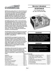
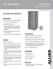
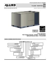
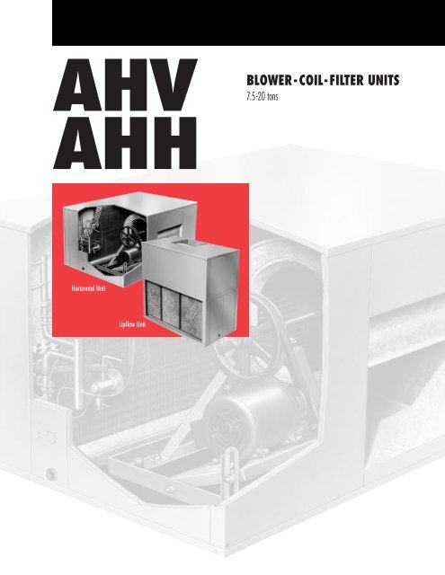
AHVBLOWER-COIL-FILTER UNITS7.5-20 tonsAHHHorizontal UnitUpflow Unit
FEATURESApplication — AHV and AHH model blower-coil filter units provideinstallation versatility and maximum efficiency in coolingperformance, air handling and filtering in cooling or heat pumpapplications. Units are available in two model styles, AHV serieswith up-flo supply air discharge or AHH series with horizontalsupply air discharge. The units are equipped with dualcircuit evaporator coils, this makes them suitable for applicationwith LSAC remote condensing units or LSAP heat pumpoutdoor units. Each indoor coil circuit has a separate expansionvalve and distribution system for two stage capacity controlduring cooling cycles. Blower coil units are shipped factory assembledready to install. Blower drives are shipped separatelyand must be ordered extra. See condensing unit bulletins (sectionSpilt System Condensing Units) or heat pump outdoorunits (section Split System — Heat Pump Units) for heatingcoolingefficiencies and capacities.Completely Tested — Blower coil units are thoroughly testedwith matching outdoor units according to ARI Standard testconditions. Blower performance data is from actual unit testsconducted in air test chamber. Units and components withinare bonded for grounding to meet safety standards for servicingrequired by U.L., N.E.C. and C.E.C.Cabinet — Cabinet is constructed of heavy gauge galvanizedsteel. A five station metal wash preparation assures a perfectbonding surface for the finish coat of baked-on enamel. Cabinetis completely lined with thick fiberglass insulation resultingin quiet and efficient operation due to the excellent sounddeadening and insulating qualities of fiberglass. Large removablepanels are provided for complete service access.Electrical inlets are conveniently located in the cabinet.Dual Circuit Copper Tube Coil — Extra large surface area ofcoil provides maximum cooling efficiency, excellent heattransfer and low air resistance. Coil is face split with separatecircuits, each circuit has its separate expansion valve. Precisecircuiting gives uniform refrigerant distribution. Fabricatedcoil is constructed of precisely spaced ripple-edged aluminumfins fitted to durable seamless rifled copper tubes. Rifled tubingprovides superior refrigerant flow resulting in maximumheat transfer. Fins are strengthened to resist bending and areequipped with collars that grip tubing for maximum contactarea. Flared tubing connections and silver soldering providetight, leakproof joints. Long life copper tubing is corrosion-resistantand easy to field service. Coil is thoroughly factorytested under high pressure to insure leakproof construction.Drain Pan — Deep, corrosion resistant drain pan isconstructed of heavy gauge galvanized steel. Equipped withtwin drain connections on both sides of cabinet as addedprotection from overflow.Belt Drive Blowers — AHV/AHH90 models are equipped witha single blower, AHV/AHH120, -180 & 240 models have dualblowers. Centrifugal belt driven blowers deliver large air volumesquietly and with low power consumption. Blowerwheels are heavy duty, with forward curved blades anddouble inlet. Wheels are statically and dynamically balancedto eliminate vibration and designed to give maximum air delivery.Bearings are heavy duty, self aligning, permanentlysealed and lubricated. All moving parts (blower wheels,drives and motor) are mounted on a rugged frame, resilientlymounted and isolated from the rest of the cabinet. Motormounting frame allows simple belt adjustment and motormounting. Adjustable motor pulley provides variable speedadjustments. A choice of motor outputs and drives are availableand must be ordered extra. See drive kit table.AHV/AHH / Page 2 Expansion Valve — Factory installed and piped. Dual circuitedcoils have two expansion valves, one for each coil section.Valves are sized for best performance.Piping And Drain Connections — Refrigerant line inlets anddrain connections are provided on both sides of the cabinet.Refrigerant lines require sweat connections and are made internalto the cabinet. Dual galvanized pipe drain outlets extendoutside the cabinet for ease of connection.Air Filters — 1 inch (25 mm) thick throwaway fiberglass mediafilters are furnished as standard. Filter rack is adjustable to accommodateup to two inch (51 mm) thick throwaway or cleanableoptional filters. Filter rack design permits quick and easyremoval of filters for servicing.OPTIONAL ACCESSORIES (Must Be Ordered Extra)Economizer Damper Section (Optional) — Factory assembledand wired economizer dampers and controls are availablefor field installation. Heavy gauge steel cabinet has abaked-on enamel finish and is completely insulated with thickmatte faced fiberglass insulation. Large removable panels onboth sides of cabinet provide complete service access.Mounting flanges provide ease of connection to unit. Flangeson outdoor air opening and return air opening permit easyduct connection. Economizer has mechanically linked outdoorair and recirculated air dampers. Formed dampers rotatesmoothly in nylon bearings. Outdoor air dampers are reinforcedand gasketed for tight seal and quiet operation.Damper linkage and shafts are plated. The positioning of thedampers is accomplished by a 24 volt fully modulating electronicspring return damper motor with adjustable minimumposition potentiometer and controlled by the room thermostat,adjustable mixed air sensor and adjustable enthalpycontrol. The enthalpy control allows 0 to 100% outdoor air tobe used for ”free cooling” when outdoor temperature and humidityare acceptable.Differential Enthalpy Control (Optional) — A solid-state returnair enthalpy sensor is available to be used with the outdoorair enthalpy control to determine which air has the lowestenthalpy. The air with the lowest enthalpy will be selected.Return air enthalpy sensor field installs in the economizerdamper section and must be ordered extra.Electric Heat (Optional) — Furnished in a separate add-onmatching cabinet. Bolts, nuts and washers are furnished tosecure cabinets together. Holes are pre-punched. Cabinet isconstructed of heavy gauge galvanized steel with a baked-onenamel finish. Completely insulated with thick fiberglass insulation.Removable panel permits service access. Electricalinlet provides wiring entry. Factory installed electric heatersare available in several sizes, see electric heat data table. Helixwound nichrome heating elements are exposed directly inthe air stream resulting in instant heat transfer, lower coiltemperatures and long service life. Elements are accuratelylocated and insulated from the heavy gauge steel supportframe by high quality insulators. Time delays bring the elementson and off the line in sequence and equal increments inresponse to demand with a time delay between each element.Elements are equipped with individual limit controlsproviding positive protection in case of excessive overheating.Heaters may be two stage controlled with each stage beingenergized only when required. Heaters must be orderedextra. Sub-fusing, contactors, control relays, 24 volt transformer,terminal block and blower motor contactor are furnishedas standard equipment.
Optional Accessories (Must Be Ordered Extra)Hot Water Heat (Optional) — Furnished in a separate add-onmatching cabinet. Bolts, nuts and washers are furnished tosecure cabinets together. Holes are pre-punched. Cabinet isconstructed of heavy gauge galvanized steel with a baked-onenamel paint finish. Completely insulated with thick mattefaced fiberglass insulation. Removable panel permits serviceaccess. Piping inlets are furnished in both sides of cabinet.Factory installed, designed and built coil has large face area,excellent heat transfer and low air resistance. Constructed ofprecisely spaced ripple-edged aluminum fins fitted to durablecopper tubes. Fins are equipped with collars that grip tubingfor maximum contact area. Flared shoulder tubing connectionsand silver soldering provide tight, leakproof joints.Long life copper tubing is easy to field service. Coil is thoroughlyfactory tested under high pressure to insure leakproofconstruction. Must be ordered extra. Valves and pumps mustbe furnished by installer.Return Air Grille (Optional) — Anodized aluminum grille fieldinstalls in return air opening of blower-coil unit. Must be orderedextra.Supply Air Plenum & Grille (Optional) — Constructed ofheavy gauge galvanized steel with a baked-on enamel paintfinish. Completely lined with thick matte faced fiberglass insulation.Equipped with anodized aluminum grille withdouble deflection and four-way directional control in verticaland horizontal planes for precise control of discharge air.Bolts, nuts and washers are furnished to secure plenum tocabinet. Must be ordered extra.Spacer Cabinets (Optional) — Matching empty spacer cabinetsgive additional height required for plenum and grille inup-flow store cooler applications and provides spacing betweenunit and plenum and grille in horizontal installationsnot using an electric heat or hot water heat cabinet.Constructed of heavy gauge galvanized steel with a baked-onenamel paint finish. Completely lined with thick matte facedfiberglass insulation. Must be ordered extra.Suspension Kits (Optional For AHH90,-120 only) — Providessupport of units in suspended horizontal applications. Kitconsists of 2 angle iron channels with holes at each end. Kitsare not available for the AHH180 & AHH240 models and mustbe field provided.Heat Pump Check Valve Kit (Optional) — Field installed kitcontains check valves with connecting tubing, sweat connections.Kit must be ordered extra. See <strong>Specifications</strong> Table.Outdoor Thermostat (Optional) — An outdoor thermostatcan be used to lock out some of the heating elements on unitswhere two stage control is applicable. Outdoor thermostatmaintains the heating load on the low power input as long aspossible before allowing the full power load to come on theline. Thermostat and mounting box must be ordered extra.Blower Contactor Kit (Optional) — Contactor kit SSA10 is notfurnished with the unit and must be ordered extra. Kit is notrequired with electric heaters. Kit requires a separate 20VA(minimum rating) transformer (not furnished).DRIVE KIT SELECTIONUsing Total Air Volume and System External Static Pressure needed for unit requirements,determine from blower performance table blower speed and blower motor output required.UnitSizeDrive KitModel NumberNominalMotor OutputMax. UsableMotor Outputhp W hp WVoltage and PhaseMinimumCircuitAmpacityRPM RangeShippingWeightlbs. kg–90–120SSA51 1.5 1119 1.7 1268 200/230/460v — 60hz — 3ph 7.5/6.5/3.3 600 — 820 39 18–90, –120–180, –240SSA41 2 1492 2.3 1716 200/230/460v — 60hz — 3ph 9.9/8.5/4.3730 — 950(90/120 models)520 — 660(180/240 models)45 20–180, –240SSA42 3 2238 3.4 2536 200/230/460v — 60hz — 3ph 13.9/12.0/6.0 600 — 750 51 23SSA43 5 3730 5.7 4252 200/230/460v — 60hz — 3ph 21.9/19.0/9.5 690 — 830 70 32Maximum useable output of motors furnished In Canada, nominal motor output is also maximum usable motor output. If motors of comparable output are used, besure to keep within the service factor limitations outlined on the motor nameplate.At rated voltages shown.INSTALLATION CLEARANCES — inches (mm)Model NumberAHV90AHH90AHV120AHH120AHV180AHH180AHV240AHH240Cabinet 0 inch (0 mm) 0 inch (0 mm) 0 inch (0 mm) 0 inch (0 mm)Plenum 1 inch (25 mm) 1 inch (25 mm) 1 inch (25 mm) 1 inch (25 mm)Duct *1 inch (*25 mm) **1 inch (**25 mm) *1 inch (*25 mm) *1 inch (*25 mm)*Within 3 feet (1 m) of the unit.**Within 4 feet (1.2 m) of the unit.AHV/AHH / Page 3
SPECIFICATIONSModel NumberAHV90AHH90AHV120AHH120AHV180AHH180AHV240AHH240Nominal Cooling Capacity — Tons (kW) 7-1/2 (26) 10 (35) 15 (53) 20 (70)Blower wheel nominal diameter x width — in. (mm) (1) 15 x 15 (381 x 381) (2)15 x 9 (381 x 229)Blower motor output and blower drives*Number and size of air filtersin.mm(2) 16 x 25 x 1(1) 20 x 25 x 1(2) 406 x 635 x 25(1) 508 x 635 x 25(2) 15 x 11 (381 x279)See Drive Kit Table (shipped separately)(4) 16 x 25 x 1(4) 406 x 635 x 25Condensate drain connection — in. (2) 1-1/4female pipe thread mm (2) 31.8(6) 16 x 20 x 1(2) 16 x 25 x 1(6) 406 x 508 x 25(2) 406 x 635 x 25(2) 15 x 15 (381 x381)(6) 20 x 20 x 1(2) 20 x 25 x 1(6) 508 x 508 x 25(2) 508 x 635 x 25RefrigerantEvaporatorCoilHCFC-22Net face area — ft. 2 (m 2) 7.98 (0.74) 10.07 (0.94) 17.38 (1.61) 23.16 (2.15)Coil split — 1st stage/2nd stage (%) 60/40 61.9/38.1 53.8/46.2 52.9/47.1Number of rows 4Tube outside diameter — in. (mm) 3/8 (9.5) 1/2 (12.7)Fins per inch (fins per m) 14 (551) 13 (512)Suction line connection — in. 1-3/8 (2) 1-1/8 (2) 1-3/8outside diameter (sweat) mm 34.9 34.9 (2) 28.5 (2) 34.9Liquid line connection — in. (2) 3/8 (2) 1/2 (4) 3/8outside diameter (sweat) mm (2) 9.5 (2) 9.5 (2) 12.7 (4) 9.5**Shipping weight — lbs. (kg) Up-flow 350 (159) 418 (190) 720 (327) 815 (370)(2 packages)Horizontal 312 (142) 379 (172) 760 (345) 860 (390) Optional Accessories (Must Be Ordered Extra) Electric Heat Model Number ES90 ES120 ES240Hot WaterCoilModel Number SSA33 SSA34 SSA35Shipping weight — lbs. (kg) 95 (43) 104 (47) 160 (73)Heating capacity — Btuh (kW) 185,000 (54.2) 257,000 (75.3) 405,000 (118.7) 462,000 (135.4)Net face area — ft. 2 (m 2 ) 6.4 (0.59) 8.5 (0.79) 15.6 (1.45)Tube outside diameter — in. (mm)number of rows1/2 (12.7)21/2 (12.7)21/2 (12.7)2Fins per inch (fins per m) 12 (472) 12 (472) 12 (472)Water line connections Inlet 1-3/8 (35) sweat 1-3/8 (35) sweat 1-5/8 (41) sweatOutside diameter — in. (mm) Outlet 1-3/8 (35) sweat 1-3/8 (35) sweat 1-5/8 (41) sweatSupply Air Plenum and Grille(shipping weight)Return Air Grille (shipping weight)Empty Spacer Cabinet (shipping weight)Economizer Dampers (shipping weight)Differential Enthalpy ControlHorizontal Suspension Kit (shipping weight)Up-flowHorizontalSSA16124 lbs. (56 kg)SSA1941 lbs. (19 kg)SSA2529 lbs. (13 kg)SSA2255 lbs. (25 kg)SSA29145 lbs. (66 kg)SSA1321 lbs. (10 kg)SSA17148 lbs. (67 kg)SSA2050 lbs. (23 kg)SSA2637 lbs. (17 kg)SSA2360 lbs. (27 kg)SSA30185 lbs. (84 kg)SSA1426 lbs. (11 kg)SSA11SSA2765 lbs. (29 kg)SSA31395 lbs. (179 kg)SSA18242 lbs. (110 kg)SSA2186 lbs. (39 kg)SSA2482 lbs. (37 kg)Not AvailableSSA2882 lbs. (37 kg)SSA32542 lbs. (264 kg)Heat Pump Check Valve Kit SSA6 SSA7 SSA9*Standard filters are 1 inch (25 mm) thick. 2 inch (51 mm) filters may also be used.**Weight does not include motor and drives.Packages consist of: blower coil unit and drive kit with motor and drives.Rated at 180F (82C) supply water temperature, 70F (21C) entering air temperature, 20F (11C) water temperature drop and 450 cfm air volume per ton (60 L/sair volume per kW) of cooling capacity. See Hot Water Capacity Curves for heating capacities at different conditions.AHV/AHH / Page 4
BLOWER DAT<strong>AAH</strong>V90 AND AHH90 BLOWER PERFORMANCESTATIC PRESSURE EXTERNAL TO UNIT — Inches Water Gauge (Pa)AirVolume 0.2 (50) 0.3 (75) 0.4 (100) 0.5 (125) 0.6 (150) 0.7 (175) 0.8 (200) 0.9 (225) 1.0 (250) 1.25 (310) 1.5 (375)cfm(L/s) RPM hp RPM hp RPM hp RPM hp RPM hp RPM hp RPM hp RPM hp RPM hp RPM hp RPM hp(W) (W) (W) (W) (W) (W) (W) (W) (W) (W) (W)2000(945) - - - - - - - - - - - -0.35 0.50 0.55 0.60 0.70 0.75 1.05 1.30550 590 630 650 690 720 790 850 (261) (373) (410) (448) (522) (560) (783) (970)2500(1180) - - - - - - - -0.30 0.55 0.65 0.75 0.80 .90 1.00 1.30 1.40560 600 630 670 700 730 760 830 880 (224) (410) (485) (560) (597) (671) (746) (970) (1044)3000(1415)3500(1650)0.60 0.65 0.75 0.85 0.95 1.00 1.15 1.25 1.30 1.55 1.80560 590 625 650 690 720 750 775 800 860 925 (448) (485) (560) (634) (709) (746) (858) (933) (970) (1156) (1343)0.95 1.05 1.05 1.15 1.30 1.35 1.50 1.60 1.65 1.95 2.20620 650 685 715 740 770 800 825 840 910 970 (709) (783) (783) (858) (970) (1007) (1119) (1194) (1231) (1455) (1641)4000(1890)1.40 1.50 1.60 1.65 1.75 1.85 1.95 2.05 2.15700 725 750 775 800 825 850 875 900 - - - - - - - -(1044) (1119) (1194) (1231) (1306) (1380) (1455) (1529) (1604)NOTE — All data is measured external to the unit with air filters in place.AHV120 AND AHH120 BLOWER PERFORMANCESTATIC PRESSURE EXTERNAL TO UNIT — Inches Water Gauge (Pa)AirVolume 0.2 (50) 0.3 (75) 0.4 (100) 0.5 (125) 0.6 (150) 0.7 (175) 0.8 (200) .9 (225) 1.0 (250) 1.25 (310) 1.5 (375)cfm(L/s) RPM hp RPM hp RPM hp RPM hp RPM hp RPM hp RPM hp RPM hp RPM hp RPM hp RPM hp(W) (W) (W) (W) (W) (W) (W) (W) (W) (W) (W)3000(1415)3500(1650)4000(1890)4500(2125)5000(2360)5500(2595)0.50 0.60 0.70 0.80 .90 1.05 1.20 1.30 1.55 1.85- - - - 550 575 610 650 680 725 750 790 860 925 (373) (448) (522) (597) (671) (783) (895) (970) (1156) (1380)0.60 0.70 0.80 .95 1.05 1.15 1.25 1.40 1.55 1.95 2.10550 575 620 650 680 725 750 790 820 900 950 (448) (522) (597) (709) (793) (858) (933) (1044) (1156) (1455) (1567)0.85 0.95 1.10 1.20 1.30 1.40 1.55 1.70 1.90 2.15595 625 665 700 725 750 790 820 850 920 - - - -(634) (709) (821) (895) (970) (1044) (1156) (1268) (1417) (1604)1.15 1.30 1.40 1.55 1.70 1.80 1.95 2.10 2.25650 680 715 740 755 810 840 870 890 - - - - - - - -(858) (970) (1044) (1156) (1268) (1343) (1455) (1567) (1679)1.55 1.70 1.80 1.95 2.15 2.30710 730 760 800 825 850 - - - - - - - - - - - - - - - - - - - -(1156) (1268) (1343) (1455) (1604) (1716)2.00 2.10 2.30750 775 815 - - - - - - - - - - - - - - - - - - - - - - - - - - - - - - - -(1492) (1567) (1716)NOTE — All data is measured external to the unit with air filters in place.AHV180 AND AHH180 BLOWER PERFORMANCESTATIC PRESSURE EXTERNAL TO UNIT — Inches Water Gauge (Pa)AirVolume 0.1 (25) 0.2 (50) 0.3 (75) 0.4 (100) 0.5 (125) 0.6 (150) 0.7 (175) 0.8 (200) 0.9 (225) 1.0 (250) 1.25 (310)cfm(L/s) RPM hp RPM hp RPM hp RPM hp RPM hp RPM hp RPM hp RPM hp RPM hp RPM hp RPM hp(W) (W) (W) (W) (W) (W) (W) (W) (W) (W) (W)5000(2360)5500(2595)6000(2830)6500(3065)7000(3305)7500(3540)8000(3775)1.00 1.05 1.20 1.50 1.55 1.65 1.75 1.90 2.25- - - - - - - - 500 530 560 630 640 660 685 720 800 (746) (783) (895) (1119) (1156) (1231) (1306) (1417) (1679)1.05 1.20 1.35 1.50 1.65 1.70 1.85 2.05 2.20 2.55- - - - 495 525 555 585 635 650 680 710 740 825 (783) (895) (1007) (1119) (1231) (1268) (1380) (1529) (1641) (1902)1.20 1.30 1.45 1.60 1.75 1.90 2.10 2.20 2.35 2.50 2.90490 520 550 580 610 640 675 705 730 760 840 (895) (970) (1082) (1194) (1306) (1417) (1567) (1641) (1753) (1865) (2163)1.45 1.60 1.75 1.90 2.05 2.25 2.35 2.50 2.65 2.75 3.30515 550 575 610 635 670 700 725 750 780 870 (1082) (1194) (1306) (1417) (1529) (1679) (1753) (1865) (1977) (2052) (2462)1.75 1.90 2.05 2.25 2.35 2.55 2.65 2.85 3.00 3.20550 575 605 635 665 690 720 745 775 810 - - - -(1306) (1417) (1529) (1679) (1753) (1902) (1977) (2126) (2238) (2387)2.05 2.25 2.55 2.45 2.75 2.90 3.05 3.25 3.40 3.55575 605 635 660 690 720 740 775 800 835 - - - -(1529) (1679) (1828) (1902) (2052) (2163) (2275) (2425) (2536) (2648)2.40 2.60 2.80 2.95 3.15 3.30 3.50 3.65 3.85 4.10605 635 660 690 720 740 775 800 835 870 - - - -(1790) (1940) (2089) (2201) (2350) (2462) (2611) (2723) (2872) (3059)NOTE — All data is measured external to the unit with air filters in place.AHV/AHH / Page 5
BLOWER DAT<strong>AAH</strong>V240 AND AHH240 BLOWER PERFORMANCESTATIC PRESSURE EXTERNAL TO UNIT — Inches Water Gauge (Pa)AirVolume 0.1 (25) 0.2 (50) 0.3 (75) 0.4 (100) 0.5 (125) 0.6 (150) 0.7 (175) 0.8 (200) 0.9 (225) 1.0 (250) 1.25 (310)cfm(L/s) RPM hp RPM hp RPM hp RPM hp RPM hp RPM hp RPM hp RPM hp RPM hp RPM hp RPM hp(W) (W) (W) (W) (W) (W) (W) (W) (W) (W) (W)6500(3065)7000(3305)7500(3540)8000(3775)8500(4010)9000(4245)9500(4485)10,000(4720)10,500(4955)1.35 1.45 1.70 1.80 1.90 2.00 2.25 2.30 2.45 2.50 2.95515 535 570 585 615 635 670 690 720 740 805 (1007) (1082) (1268) (1343) (1417) (1492) (1679) (1716) (1828) (1865) (2201)1.55 1.70 1.85 2.00 2.15 2.30 2.45 2.55 2.70 2.80 3.25525 545 575 600 625 650 680 705 730 755 820 (1156) (1268) (1380) (1492) (1604) (1716) (1828) (1902) (2014) (2089) (2425)1.70 1.85 2.05 2.25 2.30 2.55 2.65 2.80 2.90 3.15 3.60530 555 585 615 630 665 685 720 740 770 825 (1268) (1380) (1529) (1679) (1716) (1902) (1977) (2089) (2163) (2350) (2686)1.90 2.15 2.25 2.45 2.65 2.80 2.95 3.05 3.35 3.40 3.95540 565 590 625 650 675 705 730 760 785 840 (1417) (1604) (1679) (1828) (1977) (2089) (2201) (2275) (2499) (2536) (2947)2.15 2.30 2.55 2.70 2.90 3.10 3.20 3.35 3.60 3.80 4.40555 580 610 630 665 690 720 745 775 805 855 (1604) (1714) (1902) (2014) (2163) (2313) (2387) (2499) (2686) (2835) (3282)2.35 2.60 2.85 3.05 3.20 3.40 3.55 3.75 4.00 4.20 4.70565 595 630 655 680 710 735 760 795 820 870 (1753) (1940) (2126) (2275) (2387) (2536) (2648) (2798) (2894) (3133) (3506)2.65 2.95 3.15 3.05 3.55 3.75 3.90 4.15 4.40 4.65 5.15585 620 640 670 700 730 755 785 815 840 890 (1977) (2201) (2350) (2275) (2648) (2798) (2909) (3096) (3282) (3469) (3842)3.05 3.30 3.45 3.30 3.90 4.10 4.35 4.55 4.85 5.15610 635 660 690 720 750 775 805 835 860 - - - -(2275) (2462) (2574) (2462) (2909) (3059) (3245) (3394) (3618) (3842)3.35 3.55 3.80 4.05 4.30 4.60 4.75 5.05 5.40 5.70625 655 685 715 745 775 800 830 860 880 - - - -(2499) (2648) (2835) (3021) (3208) (3432) (3544) (3767) (4028) (4252)NOTE — All data is measured external to the unit with air filters in place.SUPPLY AIR PLENUM AND GRILLE AIR THROW DATA*Effective Throw — ft. (m)Blower Coil and SupplyAir VolumePlenum and Grille10 ft. (3.0 m) CeilingModel Numbercfm L/s Front of Unit 45 From Unit2000 945 40 (12.2) 31 (9.4)AHV90 With2500 1180 46 (14.0) 36 (11.0)SSA16 orAHH90 With3000 1415 53 (16.2) 41 (12.5)SSA19 3500 1650 56 (17.1) 45 (13.7)4000 1890 63 (19.2) 50 (15.2)3000 1415 50 (15.2) 35 (10.7)AHV120 With3500 1650 55 (16.8) 40 (12.2)SSA17 or 4000 1890 61 (18.6) 44 (13.4)AHH120 With4500 2125 67 (20.4) 50 (15.2)SSA205000 2360 71 (21.6) 56 (17.1)5500 2595 74 (22.6) 61 (18.6)5000 2360 30 (9.1) 19 (5.8)5500 2595 31 (9.4) 19 (5.8)AHV180 With6000 2830 35 (10.7) 22 (6.7)SSA18 orAHH180 With6500 3070 36 (11.0) 22 (6.7)SSA21 7000 3305 36 (11.0) 22 (6.7)7500 3540 39 (11.9) 24 (7.3)8000 3775 41 (12.5) 26 (7.9)6500 3070 36 (11.0) 22 (6.7)7000 3305 36 (11.0) 22 (6.7)7500 3540 39 (11.9) 24 (7.3)AHV2420 With8000 3775 41 (12.5) 26 (7.9)SSA18 orAHH240 With8500 4010 43 (13.1) 27 (8.2)SSA21 9000 4250 46 (14.0) 29 (8.8)9500 4485 49 (14.9) 30 (9.1)10,000 4720 53 (16.2) 33 (10.1)10,500 4955 55 (16.8) 34 (10.4)*Effective throw is terminated at a point where conditioned air reaches a level of 3 feet (1 m) above the floor or where velocityhas decreased to 50 feet per minute (0.25 m/s).Ceiling height not applicable to AHV Up-Flow models.AHV/AHH / Page 6
BLOWER DATAModelNumberAHV90AHH90ACCESSORY AIR RESISTANCE — AHV90, AHH90, AHH120 AND AHV120Air VolumeTotal Resistance — inches water gauge (Pa)Hot Water CoilEconomizer Damperscfm L/s SSA33 SSA34 SSA29 SSA302000 945 0.13 (32) - - - - 0.02 (5) - - - -2500 1180 0.16 (40) - - - - 0.04 (10) - - - -3000 1415 0.18 (45) - - - - 0.07 (17) - - - -3500 1650 0.20 (50) - - - - 0.09 (22) - - - -4000 1890 0.24 (60) - - - - 0.12 (30) - - - -3000 1415 - - - - 0.14 (35) - - - - 0.03 (70)3500 1650 - - - - 0.17 (42) - - - - 0.05 (12)AHV120 4000 1890 - - - - 0.18 (45) - - - - 0.07 (17)AHH120 4500 2125 - - - - 0.20 (50) - - - - 0.09 (22)5000 2360 - - - - 0.24 (60) - - - - 0.11 (27)5500 2595 - - - - 0.27 (67) - - - - 0.13 (32)NOTE — Electric heat section, plenum and grilles have no appreciable air resistance.ACCESSORY AIR RESISTANCE — AHV180, AHH180, AHH240 AND AHV240Total Resistance — inches water gauge (Pa)ModelAir VolumeHot Water CoilEconomizer DampersNumbercfm L/s SSA35 SSA31 SSA32AHV180AHH180AHV240AHH2405000 2360 0.08 (20) 0.04 (10) - - - -5500 2595 0.10 (25) 0.05 (12) - - - -6000 2830 0.11 (27) 0.06 (15) - - - -6500 3070 0.13 (32) 0.07 (17) - - - -7000 3305 0.15 (37) 0.08 (20) - - - -7500 3540 0.17 (42) 0.09 (22) - - - -8000 3775 0.18 (45) 0.10 (25) - - - -6500 3070 0.13 (32) - - - - 0.04 (10)7000 3305 0.15 (37) - - - - 0.05 (12)7500 3540 0.17 (42) - - - - 0.06 (15)8000 3775 0.18 (45) - - - - 0.07 (17)8500 4010 0.21 (52) - - - - 0.08 (20)9000 4250 0.23 (57) - - - - 0.08 (20)9500 4485 0.25 (62) - - - - 0.09 (22)10,000 4720 0.27 (67) - - - - 0.10 (25)10,500 4955 0.30 (75) - - - - 0.11 (27)NOTE — Electric heat section, plenum and grilles have no appreciable air resistance.HOT WATER COIL PRESSURE DROPFlow RatePressure Drop — feet of water (kPa)gpm L/s SSA33 SSA34 SSA3515 0.95 0.93 (3.0) 1.18 (3.5) - - - -20 1.25 1.56 (4.5) 1.99 (6.0) 0.55 (1.5)25 1.60 2.33 (7.0) 2.97 (9.0) 0.82 (2.5)30 1.90 3.24 (9.5) 4.13 (12.5) 1.14 (3.5)35 2.20 4.27 (12.5) 5.44 (16.0) 1.50 (4.5)40 2.50 5.44 (16.0) 6.92 (20.5) 1.91 (5.5)45 2.85 6.72 (20.0) 8.56 (25.5) 2.36 (7.0)50 3.15 - - - - - - - - 2.86 (8.5)55 3.45 - - - - - - - - 3.39 (10.0)60 3.80 - - - - - - - - 3.97 (12.0)65 4.10 - - - - - - - - 4.58 (13.5)70 4.40 - - - - - - - - 5.23 (15.5)AHV/AHH / Page 7
OPTIONAL ELECTRIC HEAT DATAELECTRIC HEAT FOR AHV/AHH-90 and -120Electric HeatModel No.andShipping Weight15ES90(170 lbs.)(77 kg)15ES120(193 lbs.)(88 kg)30ES90(176 lbs.)(80 kg)30ES120(200 lbs.)(91 kg)45ES90(182 lbs.)(83 kg)45ES120(207 lbs.)(94 kg)60ES120(214 lbs.)(97 kg)No.ofStepsVolts kW BtuhInput Input Output200 10.4 35,500210 11.5 39,2001 220 12.6 43,000Minimum CircuitAmpacity1-1/2 hp(1119W)2 hp(1492W)46.8 48.9230 13.8 47,100 51.4 53.4240 15.0 51,200440 12.6 43,0001 460 13.8 47,100 25.6 26.6480 15.0 51,200550 12.6 43,0001 575 13.8 47,100 21.0 21.3600 15.0 51,200200 20.8 71,000210 23.0 78,500**2 220 25.2 86,00086.3 88.4230 27.5 93,900 96.5 98.5240 30.0 102,400440 25.2 86,0001 460 27.5 93,900 48.3 49.3480 30.0 102,400550 25.2 86,0001 575 27.5 93,900 39.0 39.3600 30.0 102,400200 31.3 106,800200 34.5 117,700**3 220 37.8 129,000125.9 128.0230 41.3 141,000 141.6 143.6240 45.0 153,600440 37.8 129,000**2 460 41.3 141,000 70.8 71.8480 45.0 153,600550 37.8 129,000**2 575 41.3 141,000 57.0 57.3600 45.0 153,600200 41.7 143,400210 46.0 157,000**4 220 50.4 172,000165.4 167.5230 55.1 188,100 186.8 188.8240 60.0 204,800440 50.4 172,000**2 460 55.1 188,100 93.4 94.4480 60.0 204,800550 50.4 172,000**2 575 55.1 188,100 75.0 75.3600 60.0 204,800*Refer to National or Canadian Electrical Code manual to determine wire, fuseand disconnect size requirements. Use wires suitable for at least 167°F (75C).**May be used with two stage control.Electric HeatModel No.andShipping Weight15ES240(191 lbs.)(87 kg)30ES240(195 lbs.)(88 kg)45ES240(205 lbs)(93 kg)60ES240(209 lbs.)(95 kg)ELECTRIC HEAT FOR AHV/AHH180 and -240MinimumNo. Volts kW BtuhCircuit AmpacityofSteps Input Input Output 2 hp 3 hp 5hp(1149W) (2238W) (3730W)200 10.4 35,500210 11.5 39,2001 220 12.6 43,00048.88 52.7 60.3230 13.8 47,100 53.6 57.1 64.1240 15.0 51,200440 12.6 43,0001 460 13.8 47,100 26.8 28.6 32.1480 15.0 51,200550 12.6 43,0001 575 13.8 47,100 21.4 22.9 25.7600 15.0 51,200200 20.8 71,000210 23.0 78,500**2 220 25.2 86,00088.3 92.22 99.8230 27.5 93,900 98.8 102.3 109.3240 30.0 102,400440 25.2 86,0001 460 27.5 93,900 49.4 51.1 54.6480 30.0 102,400550 25.2 86,0001 575 27.5 93,900 39.5 41.0 43.7600 30.0 102,400200 31.3 106,800210 34.5 117,700**3 220 37.8 129,000127.8 131.6 139.33230 41.3 141,100 143.9 147.4 154.4240 45.0 153,600440 37.8 129,000**2 460 41.3 141,000 71.9 73.7 77.2480 45.0 153,600550 37.8 129,000**2 575 41.3 141,000 57.5 59.0 61.8600 45.0 153,600200 41.7 142,300210 46.0 157,000**4 220 50.4 172,000167.2 171.11 178.77230 55.1 188,100 189.0 192.5 199.5240 60.0 204,800440 50.4 172,000**2 460 55.1 188,100 94.5 96.3 99.8480 60.0 204,800550 50.4 172,000**2 575 55.1 188,100 75.5 77.1 79.8600 60.0 204,800*Refer to National or Canadian Electrical Code manual to determine wire, fuseand disconnect size requirements. Use wires suitable for at least 167°F (75C).**May be used with two stage control.AHV/AHH / Page 8
GUIDE SPECIFICATIONSPrepared for the guidance of architects, consulting engineersand mechanical contractors.General — Furnish and install a blower-coil-filter unit. Theunit shall be a standard product of a firm regularly engaged inthe manufacture of heating-cooling equipment throughoutthe United States and Canada.The installed weight shall not be more than . . . . . . . lbs. (kg).Unit shall have a width of not more than . . . . . . . inches (mm), adepth of not more than . . . . . . . inches (mm) and an overallheight of not more than . . . . . . . inches (mm).The equipment shall be shipped assembled ready for necessaryfield connections. Blower motor and pulley shall beshipped separate and field installed. AHV models shall be capableof up-flow air distribution. AHH models shall have horizontalair distribution.DX Cooling System — The total certified cooling capacityshall not be less than . . . . . . . . Btuh (kW) with an evaporator airvolume of . . . . . . . cfm (m 3 /s), an entering wet bulb temperatureof . . . . . . . F (C) and . . . . . . F (C) coil refrigerant evaporatingtemperature.The coil shall be non-ferrous construction with aluminum finsmachine fitted to copper tubes. The coil shall be dual circuitwith each circuit having an expansion valve. Coil shall be factorypressure leak tested. Coil face area shall be not less than .. . . . . . sq. ft. (m 2 ). Control option shall include Latent LoadControl.Heat Pump Heating System — The total certified heating capacityshall not be less than . . . . . . . Btuh (kW) with an indoorcoil air volume of . . . . . . .. cfm (L/s), an entering dry bulb temperatureof . . . . . . . F (C) and a condensing temperature of . . .. . . . F (C).Air Movers — Centrifugal conditioned air blowers shall havestatically and dynamically balanced, forwardly curved, doubleinlet blower wheels, permanently lubricated bearings, adjustablebelt drives and be capable of delivering . . . . . . . cfm (L/s) atan external static pressure of . . . . . . .inches water gauge (Pa),requiring not more than . . . . . . . bhp (W) and . . . . . . . rpm. AHV/AHH90 models shall be equipped with a single blower. AHV/AHH120, 180 and 240 models shall have dual blowers.Cabinet — The unit cabinet shall be constructed of galvanizedsteel with a baked-on enamel finish. Panels shall be insulatedwith not less than one inch (25mm) thick fiberglass insulation.Cabinet shall be equipped with large removable panelsproviding service access to interior. Inlets shall be providedfor refrigerant line and power connection entry. Dual drainconnections shall be accessible external to the cabinet.Air Filters — One inch (25 mm) thick throwaway filters furnishedshall have not less than . . . . . . . sq. ft. (m 2 ) of area. Filterrack shall be capable of holding optional two inch (51 mm)thick throwaway or cleanable filters.OPTIONAL ACCESSORIES (Must Be Ordered Extra)Additive Electric Heat — The certified total heating capacityoutput shall be . . . . . . . . Btuh with . . . . . . . . kw input at . . . . . . . .volts power supply.Optional electric heaters shall be available in a separatematching cabinet. Heating elements shall be nichrome barewire exposed directly to the air stream. Time delays shallbring the elements on and off in sequence with a time delaybetween each element. Limit controls shall provide overloadand short circuit protection. Cabinet shall be constructed ofgalvanized steel with a baked-on enamel paint finish and insulatedwith fiberglass insulation. Shall have removable accesspanel and electrical inlets.Additive Hot Water Heat — The certified total heating capacityoutput shall be . . . . . . . . Btuh (kW) with a heating coil airvolume of . . . . . . . cfm (L/s), at a water entering temperature of. . . . . . . F (C) and a flow rate of . . . . . . . gpm (L/s) and anentering air temperature of . . . . . . . F (C).Optional hot water coil shall be available in a separate matchingcabinet. Cabinet shall be constructed of galvanized steelwith a baked-on enamel finish and insulated with fiberglassinsulation. Shall have removable access panel and piping inletopenings. The coil shall be non-ferrous construction withaluminum fins mechanically bonded to copper tubes. Coilshall be factory pressure leak tested. Coil face area shall benot less than . . . . . . . sq. ft (m 2 ).Economizer Damper Section — Furnish and install completewith controls an optional air mixing damper assembly includingoutdoor air and recirculated air dampers. The assemblyshall provide for the introduction of outside air for minimumventilation and free cooling. The assembly shall be furnished ina fully insulated heavy gauge galvanized steel cabinet withbaked-on enamel finish. The damper motor shall be 24 volt, fullymodulating electronic spring return. Controls shall includeadjustable mixed air sensor, adjustable minimum position potentiometer,and adjustable enthalpy control. Optional differentialenthalpy control (return air sensor) shall be available.Supply Air Plenum and Grille — Optional plenum and grilleshall be constructed of galvanized steel with baked-on enamelpaint finish and insulated with fiberglass insulation. Shallbe equipped with anodized aluminum discharge air grillewith double deflection and four-way directional control in thevertical and horizontal planes.Spacer Cabinets — Optional empty cabinets shall match cabinetsections in size and provide necessary spacing betweencabinet sections for varying applications. Shall beconstructed of galvanized steel with baked-on enamel paintfinish and insulated with fiberglass insulation.Return Air Grille — Optional anodized grille shall be availablefor field addition to blower-coil unit.Suspension Kit — Kit shall be available for AHH90 andAHH120 models in suspended horizontal applications.AHV/AHH / Page 9
DIMENSIONS — inches (mm)AHV90 AND AHV120 HORIZONTAL MODELS64 (1626)52 (1321)1 (25) 1 (25)7-3/4(197)12-7/8(327)9-1/2(241)12-7/8(327)16-3/8(416)27(686)18-5/8(473)12-1/4(311) SUPPLYAIROPENING16-3/8(416)27(686)SUPPLY AIROPENINGSSUPPLY END(AHV120)ELECTRICAL INLET(Electric Heat)SUPPLY END(AHV90)27 (686)AIR FLOWELECTRICAL INLET(Electric Heat)ELECTRICAL INLET(Either Side)BLOWER2-1/16(52)2-1/2(64)24-1/2(622)47-7/8 (1216) — AHV9059-7/8 (1521) — AHV120RETURNAIROPENING1-1/2(38) 45-1/2 (1156) — AHV903/4 (19)57-1/2 (1461) — AHV1203/4 (19)INLET END2-1/16(52)EXTERNAL STATICPRESSURE TEST HOLELIQUID LINEINLETS (2)(Either Side)12-7/8(352)AIR FILTERS2 (51)AIRFLOW6 (152)2INDOOR COIL(51) 8 (203)SUCTION (VAPOR)LINE INLETS2-1/2 (Either Side)(64)44(102)(102)12-1/4(311)DRIVE END VIEWAHV180 AND AHV240 HORIZONTAL MODELS1 (25)52-1/2(1308)49(1245)2-1/2(64)CONDENSATE DRAIN (Either Side)9-3/817-3/8(238) 19 (441)16-5/819 (422)(483)(483)SUPPLY AIROPENINGSSUPPLY END85 (2159)1 (25)ELECTRICALINLET(Electric Heat)INDOOR COILAIR FILTERSAELECTRICALINLETAIR FLOW10(254)LIQUID LINEINLETS(Either Side)DBLOWERS1-5/8(41)4(102)3/4(19)Model No.AHV/AHH / Page 10 RETURNAIROPENING81-3/4 (2076)33-1/8(841)AHV180ONLY7/8(22)75-1/2 (1918)INLET VIEW42-1/8(1070)AHV240ONLY7/8(22)3/4(19)1-5/8(41)4(102)44(1118)3(76)47(1194)AIR FLOWCBCONDENSATEDRAIN(Either Side)C10-5/8(207)10-1/2(267)FF1-7/8(48)DRIVE END VIEWA B C D E Fin. mm in. mm in. mm in. mm in. mm in. mmAHV180 35 889 18-3/8 467 2-1/2 57 12-1/2 318 22-5/8 575 1-1/4 32AHV240 44 1118 22-3/4 578 2–5/8 67 14-1/4 362 22-1/2 572 4-7/8 124ESUCTION(VAPOR)LINE INLETS(Either Side)
DIMENSIONS — inches (mm)64(1626)AHH90 AND AHH120 HORIZONTAL MODELS52(1321)16-3/8(416)12-7/8(327)9-1/2(241)12-7/8(327)9-1/2(241)27(686)ELECTRICALINLET(Electric Heat)16-3/8(416)SUPPLYAIROPENING18-5/8(473)12-1/4(311)27(686)ELECTRICALINLET(Electric Heat)2-1/4(57) SUPPLY AIROPENINGS1-1/4(32)SUPPLY END(AHH120)ELECTRICAL INLET(Either Side)2-1/4(57)13-1/4(337)SUPPLY END(AHH90)36(914)EXTERNALSTATICPRESSURETEST HOLE2-1/16(52)24-1/2(622)1-1/4(32)47-7/8 (1216) — AHH9059-7/8 (1521) — AHH120RETURNAIROPENINGINLET END2-1/16(52)LIQUID LINEINLETS (2)(Either Side)AIRFLOWAIR FILTERSSUCTION (VAPOR)LINE INLET(Either Side)INDOOR COIL12-3/8(314)2 (51)6 (152)6 (152)2 (51)DRIVE END VIEWAIRFLOWCONDENSATE DRAIN(Either Side)BLOWERS85 (2159)AHH180 AND AHH240 HORIZONTAL MODELS16-5/8(422)19(483)17-3/8(441)19(483)9-3/8(238)AELECTRICALINLET(Electric Heat)1-1/2(38)G1 (25)1-1/8(29)SUPPLY AIROPENINGSSUPPLY END82 (2083)RETURNAIROPENINGELECTRICAL INLET (Either Side)AIR FILTERSSUCTION (VAPOR)LINE INLETS1-1/2 (Either Side)(38)AIRFLOWCBCF10-5/8(207)44(1118)LIQUID LINE INLETS(Either Side)EEDAIRFLOW7/8(22)INLET END10-1/2(267)7/8 (22)CONDENSATE DRAIN(Either Side)DRIVE END VIEWBLOWERSModel No.A B C D E F Gin. mm in. mm in. mm in. mm in. mm in. mm in. mmAHH180 35 889 18-3/8 467 2-1/4 57 22-5/8 575 1-1/4 32 13-1/8 333 33 838AHH240 44 1118 22-11/16 576 2-5/8 67 22-7/16 570 4-7/8 124 14-7/8 378 42 1067AHV/AHH / Page 11
OPTIONAL ACCESSORY DIMENSIONS — inches (mm)AES90 AND ES120 ELECTRIC HEAT SECTION19 (483) 7/8(22)A17-5/8(448)INLETAIROPENINGDWIRING OUTLET(To Blower Motor)19-1/2(495)ELECTRICINLETSAIRFLOW27(686)C24(610)OUTDOORAIROPENINGB1 (25)INLET VIEWFRONT VIEW1 (25)OUTLET VIEWModel No.A B C Din. mm in. mm in. mm in. mmES90 52 1321 29-7/8 759 14-9/16 370 21-1/16 535ES120 64 1626 39-7/8 1013 18-1/8 470 37-15/16 948ES240 ELECTRIC HEAT SECTION85 (2159)WIRING OUTLET(To Blower Motor)14(356)1(25)85 (2159)20-1/2(521)INLET AIROPENING14-1/2(368)20-1/2(521)20-1/4(514)16-7/8(429)AIRFLOW35(889)14-1/8 (359)OUTDOOR AIROPENING29-7/8(759)69-7/8(1775)INLET VIEW1 (25)ELECTRICINLETSFRONT VIEW1 (25)OUTLET VIEWAHOT WATER HEAT SECTION14(356)AHINLET AIROPENINGCDGAIRFLOWKHOT WATER COILBFDOUTDOOR AIROPENINGCJINLET VIEW1 (25)LWATER OUTLET(EITHER SIDE)MFRONT VIEWWATER INLET(EITHER SIDE)1 (25)OUTLET VIEWModel No. A B C D E F G H J K L MSSA33SSA34SSA35in. 52 27 41-1/2 25 50 9-1/2 1 1 1 3 2-3/8 4mm 1321 686 1054 635 1270 241 25 25 25 76 60 102in. 64 27 53-1/2 25 62 9-1/2 1 1 1 3 2-3/8 4mm 1626 686 1359 635 1575 241 25 25 25 76 60 102in. 85 35 69 33 70 13 13 2 3 2-1/4 2 2-3/4mm 2159 889 1753 838 1778 330 330 51 76 57 51 70AHV/AHH / Page 12
OPTIONAL ACCESSORY DIMENSIONS — inches (mm)AEMPTY SPACER CABINETS14(356)AHINLET AIROPENINGEDGAIRFLOWBFDOUTDOOR AIROPENINGCJ1 (25)1 (25)INLET VIEWFRONT VIEWOUTLET VIEWModel No.A B C D E F G H Jin. mm in. mm in. mm in. mm in. mm in. mm in. mm in. mm in. mmSSA22 52 1321 27 686 41-1/2 1054 25 635 50 1270 9-1/2 241 1 25 1 25 1 25SSA23 64 1626 27 686 53-1/2 1359 25 635 62 1575 9-1/2 241 1 25 1 25 1 25SSA24 85 2159 35 889 69 1753 33 838 70 1778 13 330 13 330 2 51 3 76ECONOMIZER DAMPERSDEBRECIRCULATEDAIRDAMPERSNOTE — Economizer section may be rotated180 for bottom return air connection.FTOP VIEWC1 (25) A1 (25)RETURNAIR1 (25)SUPPLYAIRTOUNITDAMPERMOTOROUTDOORAIR1 (25)CDEFBOUTDOORAIRDAMPERSSIDE VIEWEND VIEWModel No.A B C D E Fin. mm in. mm in. mm in. mm in. mm in. mmSSA29 48 1219 36 914 25 635 6 152 18 457 3-1/2 89SSA30 60 1524 48 1219 25 635 6 152 18 457 3-1/2 89SSA31 83 2108 60 1524 33 838 11-1/2 292 24 610 4-1/2 114SSA32 83 2108 60 1524 42 1067 11-1/2 292 30 762 6 152AHV/AHH / Page 13
OPTIONAL ACCESSORY DIMENSIONS — inches (mm)AHH HORIZONTAL MODELS WITH OPTIONAL ACCESSORY SECTIONSGDRETURNAIRCB4 (102)AGOUTDOORAIRECONOMIZERDAMPERSECTIONAHH BLOWERCOIL UNITESUPPLYAIRFSUPPLYAIR GRILLEOPTIONALRETURN AIR(Rotate 180)AHOT WATER CABINETEMPTY SPACER CABINETELECTRIC HEAT CABINETSPGH17SUPPLY AIR PLENUMAND GRILLEASUPPLY AIR VIEWRETURN AIRGRILLE(Optional)RETURN AIR VIEW(With Economizer)RETURN AIR VIEW(Without Economizer)GRILLE AREAGrille Free AreaModel No.sq. ft. m 2SupplySSA19 4.5 0.42Air SSA20 5.6 0.52GrilleSSA21 9.7 10.90SSA25 7.3 0.68Return SSA26 9.0 0.84AirGrille SSA27 16.5 1.53SSA28 21.2 1.97Model No.A B C D E F Gin. mm in. mm in. mm in. mm in. mm in. mm in. mmAHH90 Basic Unit 52 1321 – – – – – – 36 914 – – – – – – 27 686 – – – – – – – – – – – –AHH120 Basic Unit 64 1626 – – – – – – 36 914 – – – – – – 27 686 – – – – – – – – – – – –AHH180 Basic Unit 85 2159 – – – – – – 44 1118 – – – – – – 35 889 – – – – – – – – – – – –AHH240 Basic Unit 85 2159 – – – – – – 44 1118 – – – – – – 44 1118 – – – – – – – – – – – –ES90 Electric Heat Section 52 1321 19 483 – – – – – – 59 1499 – – – – – – 27 686 – – – – – –ES120 Electric Heat Section 64 1626 19 483 – – – – – – 59 1499 – – – – – – 27 686 – – – – – –ES240 Electric Heat Section 85 2159 14 356 – – – – – – 62 1575 – – – – – – 35 889 – – – – – –SSA33 Hot Water Coil or SSA22 Empty Spacer 52 1321 14 356 – – – – – – 54 1375 – – – – – – 27 686 – – – – – –SSA34 Hot Water Coil or SSA23 Empty Spacer 64 1626 14 356 – – – – – – 54 1375 – – – – – – 27 686 – – – – – –SSA35 Hot Water Coil or SSA24 Empty Spacer 85 2159 14 356 – – – – – – 62 1575 – – – – – – 35 889 – – – – – –SSA19 Supply Air Plenum and Grille 52 1321 – – – – – – – – – – – – – – – – – – – – – – – – 27 686 – – – – – –SSA20 Supply Air Plenum and Grille 64 1626 – – – – – – – – – – – – – – – – – – – – – – – – 27 686 – – – – – –SSA21 Supply Air Plenum and Grille 85 2159 – – – – – – – – – – – – – – – – – – – – – – – – 35 889 – – – – – –SSA29 or SSA30 Economizer – – – – – – – – – – – – – – – – – – – – – – – – – – – – – – – – – – – – 25 635SSA31 Economizer – – – – – – – – – – – – – – – – – – – – – – – – – – – – – – – – – – – – 33 838SSA32 Economizer – – – – – – – – – – – – – – – – – – – – – – – – – – – – – – – – – – – – 42 1067AHV/AHH / Page 14
OPTIONAL ACCESSORY DIMENSIONS — inches (mm)HAHV UP-FLOW MODELS WITH OPTIONAL ACCESSORY SECTIONSGSUPPLY AIR PLENUMAND GRILLECSUPPLYAIROPTIONALSUPPLY AIRHOT WATER CABINETEMPTY SPACER CABINETELECTRIC HEAT CABINETBDNOTE — Plenum may be rotated 180for change in direction of discharge air.Model No.Grille Free Areasq. ft. m 2AHV BLOWER COIL UNITRETURN AIRGRILLE(Optional)ARETURNAIRSupplyAirGrilleSSA16 4.5 0.42SSA17 5.6 0.52SSA18 9.7 0.90SSA25 7.3 0.68Return SSA26 9.0 0.84AirGrille SSA27 16.5 1.53SSA28 21.2 1.97EFRONT VIEW(Without Economizer)FDRIVE SIDE VIEW(Without Economizer)Model No.A B C D E F G Hin. mm in. mm in. mm in. mm in. mm in. mm in. mm in. mmAHV90 Basic Unit 51-1/2 1308 – – – – – – – – – – – – – – – – – – 52 1321 27 686 – – – – – – – – – – – –AHV120 Basic Unit 51-1/2 1308 – – – – – – – – – – – – – – – – – – 64 1626 27 686 – – – – – – – – – – – –AHV180 Basic Unit 47 1194 – – – – – – – – – – – – – – – – – – 85 2159 35 889 – – – – – – – – – – – –AHV240 Basic Unit 47 1194 – – – – – – – – – – – – – – – – – – 85 2159 44 1118 – – – – – – – – – – – –ES90 Electric Heat Section – – – – – – 19 483 – – – – – – 94-1/2 2400 – – – – – – – – – – – – 27 686 52 1321ES120 Electric Heat Section – – – – – – 19 483 – – – – – – 94-1/2 2400 – – – – – – – – – – – – 27 686 64 1626ES240 Electric Heat Section – – – – – – 14 356 – – – – – – 91 2311 – – – – – – – – – – – – 35 889 85 2159SSA33 Hot Water Coil or SSA22 Empty Spacer – – – – – – 14 356 – – – – – – 89-1/2 2273 – – – – – – – – – – – – 27 686 52 1321SSA34 Hot Water Coil or SSA23 Empty Spacer – – – – – – 14 356 – – – – – – 89-1/2 2273 – – – – – – – – – – – – 27 686 64 1626SSA35 Hot Water Coil or SSA34 Empty Spacer – – – – – – 14 356 – – – – – – 91 2311 – – – – – – – – – – – – 35 889 85 2159SSA16 Supply Air Plenum and Grille – – – – – – – – – – – – 24 610 – – – – – – – – – – – – – – – – – – 27 686 52 1321SSA17 Supply Air Plenum and Grille – – – – – – – – – – – – 24 610 – – – – – – – – – – – – – – – – – – 27 686 64 1626SSA18 Supply Air Plenum and Grille – – – – – – – – – – – – 30 762 91 2311 – – – – – – – – – – – – 35 889 85 2159AHV UP-FLOW MODELS WITH ECONOMIZER DAMPER SECTIONSUPPLY AIRPLENUMHOT WATER CABINETEMPTY SPACER CABINETELECTRIC HEAT CABINETAModel No.in. mmSSA29 and SSA30 25 635SSA31 33 838SSA32 42 1067SUPPLYAIRAHV BLOWER COIL UNITARETURNAIRAOUTDOORAIRECONOMIZERDAMPERSECTIONFRONT VIEW(With Economizer)DRIVE SIDE VIEW(With Economizer)AHV/AHH / Page 15
HOT WATER HEATING CAPACITY CURVESSSA35 HOT WATER HEATING CAPACITY with AHV/AHH90Btuh (1000) 120 130 140 150 160 170 180 190 200 210 220 230 240 250 260 Btuh (1000)cfm4000 35 kW 49 45 50 55 60 65 70 75 kW1800TOTAL HEATING CAPACITY3500L/s16003000 1400Water Temp.Btuh=Drop (F) 500 x U.S. gpm2500 1200L/s Air Temp.Btuhcfm=1000 Rise (F)1.08 x cfmWater Temp.kW=Drop (C) 4.19 x L/s (water)TOTAL AIR VOLUMEAir Temp.Rise (C)=kW1210 x L/s (air)SSA34 HOT WATER HEATING CAPACITY with AHV/AHH120HOT WATER WITH GLYCOL SOLUTIONCAPACITY CORRECTION FACTOR CHARTMultiply rating in hot water capacitychart by correction factor below% Of CorrectionGlycol Factor0 1.0010 .9720 .9430 .9140 .8750 .84AHV/AHH / Page 16 Btuh (1000) 120 130 140 150 160 170 180 190 200 210 220 230 240 250 260 Btuh (1000)cfm4500 35 kW 40 45 50 55 60 65 70 75 kW2000TOTAL HEATING CAPACITY4000 L/s18003500Water Temp.Btuh=1600 Drop (F) 500 x U.S. gpm30001400 Air Temp.Btuhcfm L/s=Rise (F)1.08 x cfmTOTAL AIR VOLUMEWater Temp.Drop (C)Air Temp.Rise (C)==kW4.19 x L/s (water)kW1210 x L/s (air)HOT WATER WITH GLYCOL SOLUTIONCAPACITY CORRECTION FACTOR CHARTMultiply rating in hot water capacitychart by correction factor below% Of CorrectionGlycol Factor0 1.0010 .9720 .9430 .9140 .8750 .84
HOT WATER HEATING CAPACITY CURVESSSA33 HOT WATER HEATING CAPACITY with AHV/AHH180Btuh (1000) 180 200 220 240 260 280 300 320 340 360 380 400 420 Btuh (1000)cfm7500 50 kW 60 70 80 90 100 110 120 130 kWL/sTOTAL HEATING CAPACITY340070003200HOT WATER WITH GLYCOL SOLUTIONCAPACITY CORRECTION FACTOR CHART6500Water Temp. Btuh3000=Drop (F) 500 x U.S. gpmMultiply rating in hot water capacitychart by correction factor below6000 2800Air Temp. Btuh% Of Correction=5500 2600 Rise (F) 1.08 x cfmGlycol FactorL/scfm0 1.002400 Water Temp. kW=10 .97Drop (C) 4.19 x L/s (water)20 .9430 .91Air Temp.=kW40 .87Rise (C) 1210 x L/s (air)50 .84TOTAL AIR VOLUMESSA34 HOT WATER HEATING CAPACITY with AHV/AHH240Btuh (1000) 240 260 280 300 320 340 360 380 400 420 440 460 480 Btuh (1000)cfm9500 L/s 70 kW 80 90 100 110 120 130 140 150 kW900044004200TOTAL HEATING CAPACITYHOT WATER WITH GLYCOL SOLUTION8500CAPACITY CORRECTION FACTOR CHART4000 Water Temp. Btuh=Drop (F) 500 x U.S. gpmMultiply rating in hot water capacity8000 3800chart by correction factor belowAir Temp. Btuh% Of Correction3600=7500Rise (F) 1.08 x cfmGlycol FactorL/scfm0 1.003400Water Temp. kW=10 .97Drop (C) 4.19 x L/s (water)20 .9430 .91Air Temp.=kW40 .87Rise (C) 1210 x L/s (air)50 .84TOTAL AIR VOLUMEAHV/AHH / Page 17
NOTE :<strong>Specifications</strong>, Ratings andDimensions subject tochange without notice.421 Monroe Street • Bellevue, OH 44811Form No. <strong>AAH</strong>100 (8/97) ©1997 Armstrong Air Conditioning Inc. Printed in U.S.A.