T-Series (TAA) Product Specification/EHB - Allied Commercial
T-Series (TAA) Product Specification/EHB - Allied Commercial
T-Series (TAA) Product Specification/EHB - Allied Commercial

You also want an ePaper? Increase the reach of your titles
YUMPU automatically turns print PDFs into web optimized ePapers that Google loves.
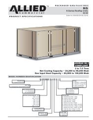
PRODUCT SPECIFICATIONSAIR HANDLERSTAT-SERIES SPLIT SYSTEM UNITSUPFLOW/HORIZONTAL - R-410A - 60 HZBulletin No. <strong>TAA</strong>-072-240 (04/2014)180-240 Models072-090-120-150 ModelsNominal Capacity - 6 to 20 TonsOptional Electric Heat - 10 to 50 kWMODEL NUMBER IDENTIFICATIONBrand/FamilyT = T-<strong>Series</strong> <strong>Product</strong> LineUnit TypeA = Split System Air HandlerT A A 120 S 4 D - 1 YVoltageY = 208/230V-3 phase-60hzG = 460V-3 phase-60hzJ = 575V-3 phase-60hzMajor Design SequenceA = 1st GenerationB = 2nd GenerationNominal Cooling Capacity - Tons072 = 6 Tons090 = 7.5 Tons120 = 10 Tons150 = 12.5 Tons180 = 15 Tons240 = 20 TonsMinor Design Sequence1 = 1st Revision2 = 2nd Revision3 = 3rd RevisionRefrigerant CircuitsS = Single CircuitD = Dual CircuitsCooling EfficiencyS = Standard EfficiencyRefrigerant Type4 = R-410A
BCDFEATURES AND BENEFITSREFRIGERANT SYSTEMMulti-Circuit, Copper Tube CoilExtra large surface provides maximum coolingefficiency, excellent heat transfer and low air resistance.Coils on 090-240 models are face split with separatecircuits, each circuit has its own expansion valve.Precise circuiting gives uniform refrigerant distribution.Coil is constructed of precisely spaced ripple edgedaluminum fins fitted to durable seamless, rifled coppertubes.Rifled tubing provides enhanced heat transfer whichresults in maximum coil performance when combinedwith fin design.Fins are strengthened to resist bending and areequipped with collars that grip tubing for maximumcontact area.Flared tubing connections and silver soldering providetight, leakproof joints.Long life copper tubing is corrosion-resistant and easyto field service.Coil is thoroughly factory tested under high pressure toensure leakproof construction.Expansion ValveFor use with R-410A systems.Factory installed and piped.Multi-circuit coils are equipped with one thermalexpansion valve per circuit.Valves are sized for best performance.090 and 120 models have internal check valves for usewith heat pump systems.Refrigerant Piping and Drain ConnectionsRefrigerant line inlets (knockouts) are provided on bothsides of the cabinet.Refrigerant lines require sweat connections and aremade internal to the cabinet.Condensate drain outlet extends outside the cabinet forease of connection. Condensate drain can be relocatedto other side of cabinet and can be repositioned forhorizontal air flow applications.Options/AccessoriesField InstalledFreezestatProtects the evaporator coil from damaging ice buildupdue to conditions such as low/no air flow, or lowrefrigerant charge.Heat Pump Check Valve Kit (180-240 Models Only)Field installed kit contains valve assemblies that fieldconvert the coil to allow it to be matched with twosmaller heat pump outdoor units.INDOOR AIR QUALITYFilters2 inch thick, throwaway fiberglass media filters arefurnished as standard.Filter rack design permits quick and easy removal offilters for servicing.Options/AccessoriesField InstalledHigh Efficiency Air FiltersDisposable MERV 11 or MERV 16 (Minimum EfficiencyReporting Value based on ASHRAE 52.2) efficiency 5inch pleated filters.5 inch pleated filters offer longer filter life and betterfiltration efficiency compared to standard 2 inch filters.5 Inch Filter Mounting KitsRequired for use with Health Climate MERV 11 orMERV 16 filters. Kit includes filter rack for 5 inch filters.UVC Germicidal Light KitsUVC light kits are specifically designed for the TA airhandlers and attach directly to the indoor coil air shieldswithout tools or fasteners at the optimal distance andlocation required. The UVC lights are sized to optimizethe reduction of mold and other bioaerosols (bacteriaand viruses) on the coil surface. In addition, the lightsare equipped with unique (patent pending) directionalhoneycomb shields to focus the UVC light on the coilsurface where it is needed and reduce the exposureof light on other components and access panels forimproved safety and overall effectiveness.Enhanced rapid start ballast provides UVC lampoperation at a full range of operating conditions.LEDs on ballast show lamp operation status.“Green” LED indicates power on”.“Blue” LED indicates lamp operation.Germicidal lamps emit ultra-violet (UVC) energy, whichhas been proven to be effective in reducing microbessuch as viruses, bacteria, yeasts, and molds. Thisprocess either destroys the organism or controls itsability to reproduce.Lamps operate on 208/230V/1ph power supply.Step-down transformer is available for models used with460V and 575V air handlers. Order separately.Lamps may be operated from separate 208/230V/1phpower source.All necessary hardware for installation is furnished.Approved by ETL.TA 6 to 20 Ton R−410A Air Handlers / Page 3
EFEATURES AND BENEFITSBELT DRIVE BLOWERS072-090-120-150 models are equipped with a singleblower wheel, 180 and 240 models have dual blowerwheels.Centrifugal belt driven blowers deliver large air volumesquietly and with low power consumption.Blower wheels are heavy-duty, with forward curvedblades and double inlet.Wheels are statically and dynamically balanced toeliminate vibration and designed to give maximum airdelivery.Bearings are heavy-duty, permanently sealed andlubricated.Belt tension is automatically controlled by autotensioning device.Adjustable motor pulley allows speed adjustments.Standard static drive is furnished factory installed. SeeBlower Drive <strong>Specification</strong>s table for optional factoryinstalled low and high static drives available.Options/AccessoriesFactory InstalledLow or High Static DrivesA choice of optional low or high static drives areavailable for factory installation. See Blower Drive<strong>Specification</strong>s table.Field InstalledSingle Zone VAV Supply Fan VFD KitExternally mounted enclosure houses a variablefrequency drive (VFD) and a control that stages thesupply air blower airflow. Designed for use on dualstagesplit systems ranging from 7.5 to 20 ton capacity(<strong>TAA</strong>090 - <strong>TAA</strong>240), the VFD alters the frequencyand voltage of the power supply to control blowermotor speed and airflow. Split dual-stage systemsequipped with this option comply with California Codeof Regulations Title 24 and ASHRAE 90.1-2010 Section6.4.3.10 requirements for staged indoor airflow.The supply air blower has two speeds:1. Low speed for part-load cooling operation.NOTE - Low speed is 66% of high speed.2. High speed for full load cooling and all heatmodes.Full speed blower operation is set by adjusting themotor pulley to deliver the desired air volume.The ventilation speed is selectable between high andlow speed.NOTE - Part load airflow in cooling mode on SingleZone VAV Supply Fan units should not be setbelow 220 cfm/nominal full load ton to reducethe risk of evaporator coil freeze-up.FNOTE - The VFD has an operational range of -40 to125°F outdoor air ambient air temperature. Attictemperatures may exceed the 125°F operatingrange. If the air handler is installed in an atticthe Single Zone VAV Supply Fan kit must bemounted remotely away from the air handlerin a location where the maximum operatingtemperature range is not exceeded.Lower operating costs are obtained when the blower isoperated on lower speeds.Mounting brackets are furnished for different mountingapplications. See the Installation Instructions for details.Single Zone VAV Supply Fan Sequence of OperationVentilation speed is determined by the VENT SPEEDswitch setting on VFD control board (LO or HI).Blower operates in low speed for mechanical cooling(Y1).Blower operates in high speed for any other mode (freecooling, mechanical cooling Y1+Y2, and heating).Economizer damper minimum position is fully closed inunoccupied mode.In occupied mode, the economizer damper minimumposition is determined by the setting of the twopotentiometers on VFD control board.• LO SPD MIN POS potentiometer sets theminimum position when blower is operating at lowspeed.• HI SPD MIN POS potentiometer sets the minimumposition when blower is operating at high speed.CONTROLSControl BoxControl box located in separate compartment in unitcabinet.Box may be relocated to alternate location for easieraccess depending on application. See dimensiondrawings.Low voltage terminal strip factory installed.Blower contactor furnished and factory installed incontrol box.All controls are pre-wired at the factory.TA 6 to 20 Ton R−410A Air Handlers / Page 4
GHOPTIONS / ACCESSORIESCABINETCabinet is constructed of heavy-gauge, galvanizedsteel.Cabinet is completely lined with thick fiberglassinsulation resulting in quiet and efficient operationdue to the excellent sound deadening and insulatingqualities of fiberglass.Supply and return air duct flanges are furnished for fieldinstallation. See dimension drawings.Service access is provided on three sides (072-150)and four sides (180-240) of unit.Large removable panels provide complete serviceaccess on one side of unit.Electrical inlets are conveniently located in the cabinet.See dimension drawingsDrain PanDeep, corrosion resistant plastic drain pan.Reversible drain pan allows for drain outlets on eitherend of cabinet and can be repositioned for horizontal airflow applications.Drain pan is removable from either side in bothhorizontal and vertical applications.Options/AccessoriesFactory InstalledCorrosion ProtectionPolymeric epoxy coating that is deposited by electricaltransport (electrophoresis), using a process knownas electrocoat (e-coat). Available for enhanced coilcorrosion protection. Factory installed on the indoor coil.Blower housing is painted when this option is ordered.Field InstalledFloat SwitchPrevents condensate overflow by turning the unit offwhen the condensate level is abnormally high.Return Air GrillesAnodized aluminum grille field installs in return airopening of air handler.Return Air Grille Free AreaT2GARD30L-1 - 4.1 sq. ft.T2GARD30M-1 - 5.9 sq. ft.T2GARD30N-1 - 7.6 sq. ft.ELECTRIC HEAT SECTIONFurnished in a separate add-on matching cabinet.Mounting hardware is furnished to secure cabinetstogether.Pre-punched mounting holes are furnished for aligningelectric heat section to air handler supply air flange.Removable panel permits service access.Electrical inlet provides wiring entry.Field installed electric heaters are available in severalkW sizes, see Electric Heat Data table.Helix wound, nichrome heating elements are exposeddirectly in the air stream resulting in instant heattransfer, lower coil temperatures and long service life.Elements are accurately located and insulated fromthe heavy-gauge steel support frame by high qualityinsulators.Elements are equipped with individual limit controlsproviding positive protection in case of overheating.Sub-fusing, contactors, control relays, 24V transformerare furnished.Certain electric heat sizes may be two-stage controlled(with field provided control) with each stage beingenergized only when required. See Electric Heat Tables.HOT WATER COILFurnished in a separate add-on matching cabinet.Mounting hardware is furnished to secure cabinetstogether.Pre-punched mounting holes are furnished for aligningcabinet to air handler.Cabinet is constructed of heavy-gauge galvanized steel.Completely insulated with thick, foil-faced fiberglassinsulation.Removable panel permits service access.Cabinet is reversible to allow piping on either side ofunit.Coil has large face area, excellent heat transfer and lowair resistance.Constructed of precisely spaced ripple-edged aluminumfins fitted to durable copper tubes.Fins are equipped with collars that grip tubing formaximum contact area.Flared shoulder tubing connections and silver solderingprovide tight, leakproof joints.Long life copper tubing is easy to field service.Coil is thoroughly factory tested under high pressure toensure leakproof construction.Valves and pumps must be furnished by installer.TA 6 to 20 Ton R−410A Air Handlers / Page 5
OPTIONS / ACCESSORIESECONOMIZER OPTIONSFactory assembled and wired economizer dampers andcontrols are available for field installation.Heavy-gauge galvanized steel cabinet is completelyinsulated with thick, matte-faced fiberglass insulation.Large removable panels on both sides of cabinetprovide complete service access.Mounting flanges provide ease of connection to airhandler unit.Flanges on outdoor air opening and return air openingpermit easy duct connection.Damper linkage and shafts are plated.Factory or Field InstalledStandard Economizer Features(Not for Title 24)Gear-driven action, return air and outdoor air dampers,plug-in connections to unit, neoprene seals, 24-volt, fully-modulating spring return motor, adjustableminimum damper position.Standard EconomizerControl ModuleThe Standard Economizer ControlModule can be adjusted to operatebased on outdoor air temperatures.Economizer Controls:• Damper Minimum Position - Canbe set lower than traditionalminimum air requirementsresulting in cost savings.• IAQ Sensor - Signals dampers to modulate andmaintain 55°F when CO 2is higher than the CO 2setpoint.• Demand Control Ventilation (DCV) LED - A steadygreen Demand Control Ventilation LED indicatesthe IAQ reading is higher than setpoint andrequires more fresh air.• Free Cool LED - A steady green LED indicatesoutdoor air is suitable for free cooling.Free Cooling runs when outdoor air temperature is lowerthan the set temperature on the economizer control.NOTE: The Free Cooling default setting for outdoor airtemperature sensor is 55°F.High PerformanceEconomizer FeaturesApproved for California Title 24 building standards.ASHRAE 90.1-2010 compliant.Gear-driven action, high torque 24-volt fully-modulatingspring return damper motor, return air and outdoor airdampers, plug-in connections to unit, nylon bearings,enhanced neoprene blade edge seals and flexiblestainless steel jamb seals to minimize air leakage.NOTE - High Performance Economizers are notapproved for use with enthalpy controls in Title 24applications.High PerformanceEconomizer Control ModuleModule provides inputs and outputs to controleconomizer based on parametersettings.Module automatically detectssensors by polling to determinewhich sensors are installed insystem.Module displays any alarm messages (fault detectionand diagnostics) as an aid in troubleshooting.Non-volatile memory retains parameter settings in caseof power failure.Keypad with four navigation buttons and LCD screen isfurnished for setting economizer parameters.• Menu Up/Exitbutton returns to the main menu.• Arrow Up button moves to the previous or nextparameter within the selected menu.• Arrow Down button moves to the next parameterwithin the selected menu.• Select (enter)selection.Main Menu Structure:button confirms parameter• STATUS (economizer and system operation status)• SETPOINTS (settings for various setpointparameters)• SYSTEM SETUP (settings/information about thesystem)• ADVANCED SETUP (freeze protection, CO 2settings, stage 3 delay and additional calibrationsettings)• CHECKOUT (damper positions)• ALARMS (output signal that can be configured forremote alarm monitoring)NOTE - The free cooling setpoint for Title 24applications must be set based on the Climate Zonewhere the system is installed. See Section 140.4“Prescriptive Requirements for Space ConditioningSystems” of the California Energy Commission’s 2013Building Energy Efficiency Standards.Refer to Installation Instructions for complete setupinformation and menu parameters available.Field InstalledDifferential Enthalpy Control(Not for Title 24)Allows the outdoor air enthalpy control to selectbetween outdoor air or return air, whichever has lowerenthalpy. Field installed in economizer damper section.TA 6 to 20 Ton R−410A Air Handlers / Page 6
UNIT CLEARANCES - INCHES (MM)3 SeeNOTES2 SeeNOTESSUPPLY AIROPENINGCOIL / UVC LIGHTACCESSTOP OR END VIEW(Depending on Application)CONTROLBOXINSTALLATION CLEARANCES (WITH ELECTRIC HEAT)FILTER/DRAIN PANACCESS1 SeeNOTESCabinet − 0 in. (0 mm)To Plenum − 0 in. (0 mm)To Outlet Duct within 3 feet (914 mm) − 0 in. (0 mm)RECOMMENDED SERVICE CLEARANCES1 Filter Removal and Routine Maintenance:36 in. (914 mm)1 Service Clearance for Drain Pan Removal:<strong>TAA</strong>072, <strong>TAA</strong>090 − 57 in. (1448 mm)<strong>TAA</strong>120, <strong>TAA</strong>150 − 73 in. (1854 mm)<strong>TAA</strong>180, <strong>TAA</strong>240 − 102 in. (2590 mm)2 Coil Cleaning / UVC Light Access (Upflow):All models − 36 in. (914 mm)3 Alternate Coil Cleaning / UVC Light Access:Provide 36 in. (914 mm) on this side if top/rear access is obstructed3 Alternate Drain/Refrigerant Line Location:Allow additional clearance if refrigerant or drain lines are routed from this side of cabinet.TA 6 to 20 Ton R−410A Air Handlers / Page 7
SPECIFICATIONSGeneralDataModel No. <strong>TAA</strong>072S4S <strong>TAA</strong>090S4DNominal Tonnage 6 7.5Connections Liquid line o.d. - in. (sweat) (1) 5/8 (2) 5/8Suction/Vapor line o.d. - in. (sweat) (1) 1-1/8 (2) 7/8Condensate drain - in. (fpt) 1 (NPT) 1 (NPT)Refrigerant Not Furnished R-410A R-410AEvaporatorCoilNet face area - sq. ft. 8.2 8.2Coil (Face) Split - 1st stage / 2nd stage (%) - - - 50 / 50Tube diameter - in. 3/8 3/8Number of rows 3 4Fins per inch 17 17See Blower Drive <strong>Specification</strong>s Table on page 16.Wheel nominal diameter & width - in. (1) 15 x 15 (1) 15 x 15Blower andDriveFilter Number and size - in. (3) 16 x 25 x 2 (3) 16 x 25 x 2SPECIFICATIONSGeneralDataModel No. <strong>TAA</strong>120S4D <strong>TAA</strong>150S4D <strong>TAA</strong>180S4D <strong>TAA</strong>240S4DNominal Tonnage 10 12.5 15 20Connections Liquid line o.d. - in. (sweat) (2) 5/8 (2) 5/8 (2) 5/8 (2) 5/8Suction/Vapor line o.d. - in. (sweat) (2) 7/8 (2) 7/8 (2) 1-1/8 (2) 1-1/8Condensate drain - in. (fpt) 1 (NPT) 1 (NPT) 1 (NPT) 1 (NPT)Refrigerant Not Furnished R-410A R-410A R-410A R-410AEvaporatorCoilNet face area - sq. ft. 11.3 11.3 16.9 16.9Coil (Face) Split - 1st stage / 2nd stage (%) 50 / 50 50 / 50 50 / 50 50 / 50Tube diameter - in. 3/8 3/8 3/8 3/8Number of rows 4 4 3 4Fins per inch 14 14 14 14See Blower Drive <strong>Specification</strong>s Table on page 16.Wheel nominal diameter & width - in. (1) 15 x 15 (1) 15 x 15 (2) 15 x 15 (2) 15 x 15Blower andDriveFilter Number and size - in. (4) 16 x 25 x 2 (4) 16 x 25 x 2 (6) 16 x 25 x 2 (6) 16 x 25 x 2OPTIONS / ACCESSORIESItemCatalogNo.072 090 120 150 180 240BLOWERBlower Drives See Blower Drive <strong>Specification</strong>s Table on page 16.Single Zone VAV Supply Fan VFD Kit2 HP 208/240V-3ph - T2MSAV20LM1Y 92W63 X X460V-3ph - T2MSAV20LM1G 92W64 X X575V-3ph - T2MSAV20LM1J 92W65 X X3 HP 208/240V-3ph - T2MSAV20LN1Y 92W66 X X X X460V-3ph - T2MSAV20LN1G 92W67 X X X X575V-3ph - T2MSAV20LN1J 92W68 X X X X5 HP 208/240V-3ph - T2MSAV20MN1Y 92W69 X X X460V-3ph - T2MSAV20MN1G 92W70 X X X575V-3ph - T2MSAV20MN1J 92W71 X X X7.5 HP 208/240V-3ph - T2MSAV20N-1Y 92W72 X460V-3ph - T2MSAV20N-1G 92W73 X575V-3ph - T2MSAV20N-1J 92W74 XCABINETCorrosion Protection Factory O O O O O OFloat Switch T2SNSR71LN1- 91W69 X X X X X XReturn Air Grille T2GARD30L-1 47W49 X XT2GARD30M-1 47W50 X XT2GARD30N-1 47W51 X XNOTE - The catalog and model numbers that appear here are for ordering field installed accessories only.O - Factory Installed with extended lead time.X - Field Installed.TA 6 to 20 Ton R−410A Air Handlers / Page 8
OPTIONS / ACCESSORIESItemCatalogNo.072 090 120 150 180 240ELECTRIC HEAT10 kW 208/240V-3ph - T3EH0010LM1Y 46W50 X X X X460V-3ph - T3EH0010LM1G 46W55 X X X X575V-3ph - T3EH0010LM1J 46W60 X X X X15 kW 208/240V- 3ph - T3EH0015LM1Y 46W51 X x X X460V-3ph - T3EH0015LM1G 46W56 X X X X575V-3ph - T3EH0015LM1J 46W61 X X X X25 kW 208/240V-3ph - T3EH0025LM1Y 46W52 X X X X460V-3ph - T3EH0025LM1G 46W57 X X X X575V-3ph - T3EH0025LM1J 46W62 X X X X35 kW 208/240V-3ph - T3EH0035LM1Y 46W53 X X X460V-3ph - T3EH0035LM1G 46W58 X X X575V-3ph - T3EH0035LM1J 46W63 X X X20 kW 208/240V-3ph - T3EH0020N-1Y 46W65 X X460V-3ph - T3EH0020N-1G 46W69 X X575V-3ph - T3EH0020N-1J 46W73 X X30 kW 208/240V-3ph - T3EH0030N-1Y 46W66 X X460V-3ph - T3EH0030N-1G 46W70 X X575V-3ph - T3EH0030N-1J 46W74 X X40 kW 208/240V-3ph - T3EH0040N-1Y 49W39 X X460V-3ph - T3EH0040N-1G 49W40 X X575V-3ph - T3EH0040N-1J 49W41 X X50 kW 208/240V-3ph - T3EH0050N-1Y 46W67 X X460V-3ph - T3EH0050N-1G 46W71 X X575V-3ph - T3EH0050N-1J 46W75 X XECONOMIZERStandard Economizers (Not for Title 24)T2ECON31L-1- 44W94 X XT2ECON31M-1- 44W95 X XT2ECON31N-1- 44W96 X XStandard Economizer Controls (Not for Title 24)Differential Enthalpy Control T1SNSR60AN1 17W71 X X X X X XHigh Performance Economizers (Approved for California Title 24 Building Standards)T2ECON34L-1 10U48 X XT2ECON34M-1 10U49 X XT2ECON34N-1 10U50 X XHigh Performance Economizer Controls (Not for Title 24)Differential Enthalpy Control C1NSR61FF1 11G21HOT WATER COILT2HWCL10LM1- 44W20 X X X XT2HWCL10N-1- 44W21 X XINDOOR AIR QUALITYAir Filters1High EfficiencyAir Filters (16 x 25 x 5)MERV 11 - HCF16-11 X6670 X X X X X XMERV 16 - HCF16-16 X6672 X X X X X X5 Inch Filter Mounting Kits T2FLTR70L-1- 47W71 X XT2FLTR70M-1- 47W72 X XT2FLTR70N-1- 47W73 X XUVC Light Kit(208/230V-1ph)208/230V - T2UVCL10LM1 46W43 X X X X208/230V - T2UVCL10N-1 46W44 X X2460V/230V Step-Down Transformer 96M07 X X X X X X2575V/230V Step-Down Transformer 96M08 X X X X X XREFRIGERANT SYSTEMFreezestat T2SNSR70N1- 91W70 X X X X X XHeat Pump Check Valve Kit T2CVLV10N-1- 47W48 XT2CVLV11N-1- 50W73 XNOTE - The catalog and model numbers that appear here are for ordering field installed accessories only.X - Field Installed.1Order 5 in. Filter Mounting Kit and required number of MERV 11 or MERV 16 filters: - (3) 072-090, (4) 120-150, (6) 180-240.2Step-down transformer (460V or 575V to 208/230V-1ph) or separate power supply is required.TA 6 to 20 Ton R−410A Air Handlers / Page 9
BLOWER DATA<strong>TAA</strong>072 BLOWER PERFORMANCEAll data is measured external to the unit with dry coil and standard 2 in. air filters in place.FOR ALL UNITS ADD:1 - Wet indoor coil air resistance of selected unit.2 - Any field installed accessories air resistance (electric heat, economizer, etc.) See page 17.Then determine from table the blower motor hp and drive rpm required. See page 16 for blower drive specifications.AirVolumecfmSTATIC PRESSURE EXTERNAL TO UNIT - Inches Water Gauge0.1 0.2 0.3 0.4 0.5 0.6 0.7 0.8RPM BHP RPM BHP RPM BHP RPM BHP RPM BHP RPM BHP RPM BHP RPM BHP1900 428 0.57 479 0.66 531 0.74 581 0.81 629 0.88 675 0.94 718 1.01 758 1.072000 434 0.59 486 0.69 538 0.77 589 0.84 637 0.91 682 0.98 725 1.05 765 1.112100 441 0.62 493 0.72 545 0.8 596 0.88 644 0.95 689 1.02 732 1.09 771 1.152200 448 0.65 501 0.75 553 0.83 604 0.91 652 0.98 696 1.06 738 1.13 778 1.22300 456 0.68 508 0.78 561 0.86 612 0.94 659 1.02 704 1.1 746 1.17 785 1.242400 463 0.71 516 0.81 569 0.9 620 0.98 667 1.06 711 1.14 753 1.22 792 1.292500 470 0.74 524 0.84 578 0.94 629 1.02 675 1.1 719 1.19 760 1.27 798 1.342600 478 0.77 533 0.88 587 0.98 637 1.06 683 1.15 726 1.24 767 1.32 805 1.392700 486 0.81 542 0.92 596 1.02 646 1.11 692 1.2 734 1.29 775 1.37 812 1.452800 495 0.85 552 0.96 606 1.07 655 1.16 700 1.25 742 1.34 782 1.42 819 1.52900 504 0.89 561 1.01 616 1.11 665 1.2 708 1.3 750 1.39 789 1.48 826 1.563000 514 0.93 572 1.05 626 1.16 674 1.26 717 1.35 758 1.45 797 1.54 833 1.62AirVolumecfmSTATIC PRESSURE EXTERNAL TO UNIT - Inches Water Gauge0.9 1 1.1 1.2 1.3 1.4 1.5RPM BHP RPM BHP RPM BHP RPM BHP RPM BHP RPM BHP RPM BHP1900 796 1.13 830 1.19 862 1.25 893 1.32 922 1.39 950 1.46 978 1.542000 802 1.17 836 1.23 868 1.3 898 1.37 928 1.44 956 1.52 983 1.62100 808 1.22 842 1.28 874 1.35 904 1.42 933 1.5 961 1.58 988 1.662200 814 1.26 848 1.33 879 1.4 909 1.48 938 1.56 966 1.64 993 1.732300 820 1.31 854 1.38 885 1.46 915 1.53 943 1.62 971 1.7 998 1.792400 827 1.36 860 1.43 891 1.51 920 1.59 949 1.68 976 1.77 1003 1.862500 833 1.41 866 1.49 897 1.57 926 1.66 954 1.75 981 1.84 1008 1.932600 840 1.47 872 1.55 902 1.63 932 1.72 960 1.81 987 1.91 1013 2.012700 846 1.53 878 1.61 908 1.7 937 1.79 965 1.88 992 1.98 1018 2.082800 853 1.58 884 1.67 914 1.76 943 1.86 970 1.96 997 2.06 1023 2.162900 859 1.65 890 1.74 920 1.83 948 1.93 975 2.03 1002 2.14 1028 2.243000 866 1.71 896 1.8 926 1.9 954 2 981 2.11 1007 2.22 1032 2.33TA 6 to 20 Ton R−410A Air Handlers / Page 10
BLOWER DATA<strong>TAA</strong>090 BLOWER PERFORMANCEAll data is measured external to the unit with dry coil and standard 2 in. air filters in place.FOR ALL UNITS ADD:1 - Wet indoor coil air resistance of selected unit.2 - Any field installed accessories air resistance (electric heat, economizer, etc.) See page 17.Then determine from table the blower motor hp and drive rpm required. See page 16 for blower drive specifications.AirVolumecfmSTATIC PRESSURE EXTERNAL TO UNIT - Inches Water Gauge0.1 0.2 0.3 0.4 0.5 0.6 0.7 0.8RPM BHP RPM BHP RPM BHP RPM BHP RPM BHP RPM BHP RPM BHP RPM BHP1600 430 0.52 485 0.62 539 0.71 590 0.77 636 0.83 680 0.88 721 0.94 758 0.991700 439 0.55 494 0.65 548 0.74 599 0.80 645 0.86 688 0.91 729 0.97 766 1.031800 448 0.58 503 0.68 558 0.77 608 0.83 654 0.89 697 0.95 737 1.01 774 1.081900 457 0.62 513 0.72 567 0.80 617 0.86 663 0.93 705 0.99 745 1.06 781 1.122000 467 0.65 523 0.75 577 0.83 627 0.90 672 0.96 714 1.03 753 1.10 789 1.172100 477 0.68 533 0.78 587 0.86 637 0.93 681 1.00 723 1.08 762 1.15 797 1.222200 487 0.72 543 0.82 597 0.90 646 0.97 691 1.05 732 1.12 770 1.20 805 1.272300 497 0.75 554 0.85 608 0.94 657 1.01 700 1.09 741 1.17 779 1.25 813 1.322400 508 0.79 565 0.89 619 0.98 667 1.06 710 1.14 750 1.23 787 1.30 822 1.382500 519 0.83 577 0.94 630 1.02 677 1.10 720 1.19 759 1.28 796 1.36 830 1.432600 531 0.87 588 0.98 641 1.07 688 1.16 729 1.25 769 1.34 805 1.42 839 1.492700 543 0.92 600 1.03 653 1.12 698 1.21 739 1.31 778 1.40 814 1.48 848 1.552800 555 0.97 613 1.08 664 1.17 709 1.27 749 1.37 788 1.46 824 1.54 857 1.622900 568 1.02 625 1.13 676 1.22 719 1.32 759 1.43 797 1.52 833 1.60 866 1.683000 581 1.07 638 1.18 687 1.28 730 1.39 769 1.49 807 1.58 842 1.67 875 1.753100 595 1.12 651 1.24 699 1.34 740 1.45 779 1.56 817 1.65 852 1.73 883 1.823200 609 1.18 664 1.30 710 1.41 751 1.52 789 1.63 827 1.72 861 1.80 892 1.893300 624 1.24 677 1.36 722 1.48 761 1.59 799 1.70 836 1.79 870 1.88 901 1.973400 639 1.30 690 1.43 733 1.55 772 1.67 810 1.77 846 1.86 879 1.95 909 2.053500 653 1.37 703 1.50 745 1.62 782 1.75 820 1.85 856 1.94 888 2.03 917 2.143600 668 1.44 715 1.57 756 1.70 793 1.83 830 1.93 865 2.02 897 2.12 925 2.24AirVolumecfmSTATIC PRESSURE EXTERNAL TO UNIT - Inches Water Gauge0.9 1 1.1 1.2 1.3 1.4 1.5RPM BHP RPM BHP RPM BHP RPM BHP RPM BHP RPM BHP RPM BHP1600 793 1.05 826 1.10 859 1.15 891 1.21 923 1.27 952 1.34 981 1.421700 800 1.09 833 1.15 866 1.20 899 1.26 930 1.33 959 1.40 987 1.481800 807 1.13 840 1.19 873 1.25 906 1.31 936 1.38 966 1.46 994 1.541900 815 1.18 848 1.24 881 1.30 913 1.36 943 1.44 972 1.52 1000 1.602000 823 1.23 856 1.29 889 1.35 921 1.42 951 1.50 979 1.58 1007 1.672100 830 1.28 863 1.34 896 1.40 928 1.48 958 1.56 986 1.65 1013 1.742200 838 1.33 871 1.39 904 1.46 935 1.54 965 1.63 993 1.72 1020 1.812300 846 1.39 880 1.45 912 1.52 943 1.61 972 1.70 999 1.79 1026 1.882400 855 1.44 888 1.51 920 1.59 950 1.67 979 1.77 1006 1.86 1033 1.962500 863 1.50 896 1.57 928 1.65 958 1.74 986 1.84 1013 1.94 1039 2.042600 872 1.56 904 1.64 936 1.72 965 1.82 993 1.92 1019 2.02 1045 2.122700 880 1.62 913 1.70 943 1.79 972 1.89 1000 2.00 1026 2.10 1052 2.202800 889 1.69 921 1.77 951 1.87 979 1.97 1006 2.08 1033 2.18 1058 2.292900 898 1.76 929 1.85 959 1.95 987 2.05 1013 2.16 1039 2.26 1064 2.373000 906 1.83 937 1.93 966 2.03 994 2.13 1020 2.24 1046 2.35 1070 2.463100 914 1.91 944 2.01 973 2.11 1001 2.22 1027 2.33 1052 2.44 1077 2.553200 922 1.99 952 2.09 980 2.20 1008 2.30 1033 2.41 1058 2.53 1083 2.643300 930 2.07 959 2.18 987 2.29 1014 2.39 1040 2.50 1065 2.62 1089 2.733400 938 2.16 966 2.27 994 2.38 1021 2.49 1046 2.60 1071 2.71 1095 2.833500 945 2.26 973 2.37 1001 2.48 1028 2.58 1053 2.69 1077 2.81 1101 2.933600 953 2.35 980 2.47 1008 2.58 1034 2.68 1059 2.79 1084 2.91 1107 3.03TA 6 to 20 Ton R−410A Air Handlers / Page 11
BLOWER DATA<strong>TAA</strong>120 BLOWER PERFORMANCEAll data is measured external to the unit with dry coil and standard 2 in. air filters in place.FOR ALL UNITS ADD:1 - Wet indoor coil air resistance of selected unit.2 - Any field installed accessories air resistance (electric heat, economizer, etc.) See page 17.Then determine from table the blower motor hp and drive rpm required. See page 16 for blower drive specifications.AirVolumecfmSTATIC PRESSURE EXTERNAL TO UNIT - Inches Water Gauge0.1 0.2 0.3 0.4 0.5 0.6 0.7 0.8RPM BHP RPM BHP RPM BHP RPM BHP RPM BHP RPM BHP RPM BHP RPM BHP2200 441 0.11 483 0.27 524 0.42 565 0.55 605 0.65 643 0.74 678 0.80 713 0.852400 452 0.20 494 0.36 536 0.51 576 0.63 616 0.73 653 0.81 688 0.87 722 0.922600 463 0.30 505 0.45 547 0.60 588 0.72 627 0.82 664 0.89 699 0.95 731 1.002800 475 0.39 517 0.55 559 0.69 600 0.81 638 0.90 675 0.98 709 1.04 742 1.093000 487 0.49 529 0.65 571 0.79 612 0.91 650 1.00 687 1.07 721 1.13 752 1.193200 500 0.60 542 0.75 584 0.89 624 1.01 663 1.10 699 1.17 732 1.23 764 1.303400 513 0.71 555 0.86 597 1.00 638 1.11 676 1.20 711 1.28 745 1.35 775 1.423600 526 0.82 569 0.98 611 1.12 651 1.23 689 1.32 725 1.40 757 1.47 788 1.553800 540 0.93 583 1.10 626 1.24 666 1.36 704 1.45 739 1.53 771 1.61 801 1.694000 554 1.05 598 1.23 641 1.38 682 1.50 719 1.60 753 1.68 785 1.76 814 1.854200 569 1.18 614 1.37 658 1.53 698 1.65 735 1.75 768 1.84 799 1.92 828 2.024400 585 1.33 631 1.53 675 1.69 715 1.82 751 1.93 784 2.01 814 2.10 843 2.204600 603 1.50 650 1.71 694 1.88 733 2.01 769 2.11 800 2.20 829 2.29 858 2.404800 622 1.68 670 1.90 714 2.07 752 2.20 786 2.30 816 2.39 845 2.48 873 2.615000 643 1.89 691 2.11 734 2.28 771 2.40 804 2.50 833 2.59 860 2.69 888 2.82AirVolumecfmSTATIC PRESSURE EXTERNAL TO UNIT - Inches Water Gauge0.9 1 1.1 1.2 1.3 1.4 1.5RPM BHP RPM BHP RPM BHP RPM BHP RPM BHP RPM BHP RPM BHP2200 746 0.89 780 0.95 814 1.01 847 1.07 880 1.14 912 1.21 941 1.292400 754 0.97 787 1.03 821 1.10 854 1.17 887 1.25 918 1.32 947 1.402600 763 1.06 796 1.12 829 1.20 862 1.28 895 1.36 926 1.45 955 1.532800 773 1.15 805 1.22 838 1.30 871 1.39 904 1.48 935 1.58 964 1.673000 783 1.26 815 1.34 848 1.43 881 1.52 914 1.62 944 1.72 973 1.823200 794 1.37 826 1.46 858 1.56 892 1.66 924 1.76 955 1.87 983 1.983400 806 1.50 837 1.60 870 1.70 903 1.81 935 1.92 965 2.04 994 2.153600 818 1.64 849 1.74 882 1.86 915 1.97 947 2.09 977 2.21 1004 2.333800 831 1.79 862 1.91 895 2.03 928 2.15 959 2.28 988 2.40 1015 2.524000 844 1.96 876 2.08 908 2.21 941 2.34 972 2.47 1000 2.60 1026 2.724200 858 2.14 890 2.27 922 2.40 954 2.54 984 2.68 1012 2.81 1037 2.944400 873 2.33 904 2.47 936 2.61 968 2.75 997 2.89 1024 3.03 1048 3.164600 887 2.53 919 2.68 950 2.83 981 2.97 1010 3.12 1035 3.26 1058 3.394800 902 2.75 934 2.90 965 3.06 995 3.21 1022 3.36 1046 3.51 1068 3.645000 918 2.98 948 3.14 979 3.30 1008 3.46 1034 3.61 1057 3.76 1077 3.89TA 6 to 20 Ton R−410A Air Handlers / Page 12
BLOWER DATA<strong>TAA</strong>150 BLOWER PERFORMANCEAll data is measured external to the unit with dry coil and standard 2 in. air filters in place.FOR ALL UNITS ADD:1 - Wet indoor coil air resistance of selected unit.2 - Any field installed accessories air resistance (electric heat, economizer, etc.) See page 17.Then determine from table the blower motor hp and drive rpm required. See page 16 for blower drive specifications.AirVolumecfmSTATIC PRESSURE EXTERNAL TO UNIT - Inches Water Gauge0.1 0.2 0.3 0.4 0.5 0.6 0.7 0.8RPM BHP RPM BHP RPM BHP RPM BHP RPM BHP RPM BHP RPM BHP RPM BHP2800 475 0.39 517 0.55 559 0.69 600 0.81 638 0.90 675 0.98 709 1.04 742 1.093000 487 0.49 529 0.65 571 0.79 612 0.91 650 1.00 687 1.07 721 1.13 752 1.193200 500 0.60 542 0.75 584 0.89 624 1.01 663 1.10 699 1.17 732 1.23 764 1.303400 513 0.71 555 0.86 597 1.00 638 1.11 676 1.20 711 1.28 745 1.35 775 1.423600 526 0.82 569 0.98 611 1.12 651 1.23 689 1.32 725 1.40 757 1.47 788 1.553800 540 0.93 583 1.10 626 1.24 666 1.36 704 1.45 739 1.53 771 1.61 801 1.694000 554 1.05 598 1.23 641 1.38 682 1.50 719 1.60 753 1.68 785 1.76 814 1.854200 569 1.18 614 1.37 658 1.53 698 1.65 735 1.75 768 1.84 799 1.92 828 2.024400 585 1.33 631 1.53 675 1.69 715 1.82 751 1.93 784 2.01 814 2.10 843 2.204600 603 1.50 650 1.71 694 1.88 733 2.01 769 2.11 800 2.20 829 2.29 858 2.404800 622 1.68 670 1.90 714 2.07 752 2.20 786 2.30 816 2.39 845 2.48 873 2.615000 643 1.89 691 2.11 734 2.28 771 2.40 804 2.50 833 2.59 860 2.69 888 2.825200 666 2.12 714 2.34 756 2.49 791 2.61 822 2.70 849 2.79 876 2.91 903 3.055400 691 2.37 738 2.57 777 2.72 810 2.82 839 2.91 865 3.01 891 3.13 919 3.295600 718 2.63 762 2.82 799 2.94 829 3.04 856 3.13 881 3.23 907 3.37 934 3.535800 746 2.91 786 3.06 820 3.17 848 3.26 872 3.36 896 3.47 922 3.62 949 3.806000 774 3.18 810 3.31 840 3.40 865 3.49 888 3.59 911 3.72 936 3.88 963 4.08AirVolumecfmSTATIC PRESSURE EXTERNAL TO UNIT - Inches Water Gauge0.9 1 1.1 1.2 1.3 1.4 1.5RPM BHP RPM BHP RPM BHP RPM BHP RPM BHP RPM BHP RPM BHP2800 773 1.15 805 1.22 838 1.30 871 1.39 904 1.48 935 1.58 964 1.673000 783 1.26 815 1.34 848 1.43 881 1.52 914 1.62 944 1.72 973 1.823200 794 1.37 826 1.46 858 1.56 892 1.66 924 1.76 955 1.87 983 1.983400 806 1.50 837 1.60 870 1.70 903 1.81 935 1.92 965 2.04 994 2.153600 818 1.64 849 1.74 882 1.86 915 1.97 947 2.09 977 2.21 1004 2.333800 831 1.79 862 1.91 895 2.03 928 2.15 959 2.28 988 2.40 1015 2.524000 844 1.96 876 2.08 908 2.21 941 2.34 972 2.47 1000 2.60 1026 2.724200 858 2.14 890 2.27 922 2.40 954 2.54 984 2.68 1012 2.81 1037 2.944400 873 2.33 904 2.47 936 2.61 968 2.75 997 2.89 1024 3.03 1048 3.164600 887 2.53 919 2.68 950 2.83 981 2.97 1010 3.12 1035 3.26 1058 3.394800 902 2.75 934 2.90 965 3.06 995 3.21 1022 3.36 1046 3.51 1068 3.645000 918 2.98 948 3.14 979 3.30 1008 3.46 1034 3.61 1057 3.76 1077 3.895200 933 3.21 963 3.38 993 3.55 1020 3.72 1045 3.88 1067 4.02 1086 4.155400 948 3.46 978 3.64 1006 3.82 1033 3.99 1056 4.15 1077 4.30 1095 4.435600 963 3.72 992 3.91 1019 4.09 1044 4.27 1067 4.43 1086 4.58 1104 4.715800 977 3.99 1005 4.19 1032 4.38 1056 4.56 1077 4.73 1096 4.88 1114 5.016000 991 4.28 1019 4.49 1044 4.69 1067 4.87 1087 5.04 1106 5.19 1123 5.33TA 6 to 20 Ton R−410A Air Handlers / Page 13
BLOWER DATA<strong>TAA</strong>180 BLOWER PERFORMANCEAll data is measured external to the unit with dry coil and standard 2 in. air filters in place.FOR ALL UNITS ADD:1 - Wet indoor coil air resistance of selected unit.2 - Any field installed accessories air resistance (electric heat, economizer, etc.) See page 17.Then determine from table the blower motor hp and drive rpm required. See page 16 for blower drive specifications.AirVolumecfmSTATIC PRESSURE EXTERNAL TO UNIT - Inches Water Gauge0.1 0.2 0.3 0.4 0.5 0.6 0.7 0.8RPM BHP RPM BHP RPM BHP RPM BHP RPM BHP RPM BHP RPM BHP RPM BHP3400 393 0.60 439 0.81 486 1.00 533 1.16 579 1.28 624 1.41 667 1.56 708 1.713600 398 0.66 444 0.87 491 1.06 538 1.21 583 1.33 628 1.47 671 1.62 711 1.793800 403 0.72 449 0.92 496 1.11 542 1.26 587 1.39 632 1.53 675 1.69 715 1.864000 408 0.78 454 0.98 501 1.17 547 1.32 592 1.45 636 1.60 679 1.76 718 1.944200 413 0.84 459 1.04 506 1.23 552 1.38 597 1.52 641 1.67 683 1.84 722 2.034400 419 0.90 465 1.10 512 1.29 558 1.44 602 1.58 645 1.74 687 1.92 726 2.124600 424 0.97 470 1.17 517 1.35 563 1.50 607 1.65 651 1.82 692 2.01 730 2.214800 430 1.03 476 1.23 523 1.42 569 1.57 613 1.73 656 1.90 697 2.10 735 2.315000 436 1.09 482 1.30 530 1.49 575 1.64 619 1.81 661 1.99 702 2.19 739 2.425200 442 1.15 489 1.37 536 1.56 582 1.72 625 1.89 667 2.08 707 2.29 744 2.525400 448 1.21 495 1.44 543 1.64 588 1.80 631 1.98 673 2.18 712 2.40 749 2.635600 454 1.28 502 1.52 550 1.72 595 1.89 638 2.08 679 2.28 718 2.51 754 2.755800 460 1.35 510 1.60 558 1.80 602 1.98 645 2.18 686 2.39 724 2.62 759 2.876000 467 1.43 517 1.68 566 1.89 610 2.07 652 2.28 692 2.50 729 2.74 764 2.996200 475 1.51 526 1.78 574 1.98 617 2.17 659 2.39 699 2.61 735 2.86 770 3.126400 483 1.60 534 1.87 582 2.08 625 2.28 666 2.50 705 2.73 741 2.99 775 3.256600 491 1.70 544 1.97 591 2.18 633 2.39 674 2.62 712 2.86 747 3.12 781 3.386800 501 1.81 553 2.08 600 2.29 642 2.51 682 2.74 719 2.99 753 3.26 786 3.527000 511 1.92 563 2.19 609 2.40 650 2.63 689 2.87 725 3.13 759 3.40 792 3.667200 521 2.04 573 2.30 618 2.52 659 2.76 697 3.01 732 3.27 765 3.54 798 3.80AirVolumecfmSTATIC PRESSURE EXTERNAL TO UNIT - Inches Water Gauge0.9 1 1.1 1.2 1.3 1.4 1.5RPM BHP RPM BHP RPM BHP RPM BHP RPM BHP RPM BHP RPM BHP3400 746 1.87 783 2.02 819 2.16 857 2.31 897 2.48 936 2.65 976 2.833600 749 1.95 786 2.11 822 2.26 860 2.42 900 2.58 939 2.76 979 2.933800 752 2.04 789 2.21 825 2.36 863 2.52 903 2.69 943 2.86 983 3.044000 756 2.13 792 2.30 829 2.47 867 2.63 906 2.80 946 2.97 986 3.154200 759 2.22 795 2.40 832 2.57 870 2.74 910 2.91 950 3.08 990 3.264400 763 2.32 799 2.51 836 2.68 874 2.85 913 3.02 953 3.19 993 3.374600 767 2.42 803 2.61 840 2.79 878 2.96 917 3.13 957 3.31 997 3.484800 771 2.53 807 2.72 844 2.91 882 3.08 921 3.25 961 3.42 1001 3.595000 775 2.63 811 2.84 848 3.02 886 3.20 925 3.37 965 3.54 1005 3.715200 780 2.75 815 2.95 852 3.14 890 3.32 929 3.49 969 3.67 1009 3.845400 784 2.86 820 3.07 857 3.26 895 3.44 934 3.62 974 3.80 1014 3.975600 789 2.98 824 3.19 861 3.38 900 3.57 939 3.75 978 3.93 1018 4.115800 794 3.10 829 3.32 866 3.51 905 3.70 944 3.88 983 4.07 1023 4.256000 799 3.23 834 3.44 871 3.64 910 3.83 949 4.02 988 4.21 1028 4.406200 804 3.36 839 3.57 876 3.77 915 3.97 954 4.16 994 4.35 1033 4.556400 809 3.49 844 3.70 881 3.90 920 4.10 960 4.30 999 4.50 1039 4.706600 815 3.62 850 3.83 887 4.04 926 4.24 965 4.45 1005 4.65 1044 4.856800 820 3.76 855 3.97 892 4.18 931 4.39 971 4.59 1011 4.80 1050 5.017000 826 3.89 861 4.11 898 4.32 937 4.53 977 4.74 1016 4.95 1056 5.167200 831 4.03 866 4.25 904 4.46 943 4.67 982 4.89 1022 5.10 1062 5.32TA 6 to 20 Ton R−410A Air Handlers / Page 14
BLOWER DATA<strong>TAA</strong>240 BLOWER PERFORMANCEAll data is measured external to the unit with dry coil and standard 2 in. air filters in place.FOR ALL UNITS ADD:1 - Wet indoor coil air resistance of selected unit.2 - Any field installed accessories air resistance (electric heat, economizer, etc.) See page 17.Then determine from table the blower motor hp and drive rpm required. See page 16 for blower drive specifications.AirVolumecfmSTATIC PRESSURE EXTERNAL TO UNIT - Inches Water Gauge0.1 0.2 0.3 0.4 0.5 0.6 0.7 0.8RPM BHP RPM BHP RPM BHP RPM BHP RPM BHP RPM BHP RPM BHP RPM BHP4400 449 1.05 493 1.22 539 1.38 584 1.52 628 1.68 670 1.85 711 2.04 748 2.244600 456 1.11 501 1.29 546 1.45 591 1.60 635 1.76 677 1.94 717 2.14 754 2.354800 463 1.17 509 1.36 554 1.53 599 1.68 642 1.85 684 2.03 723 2.24 760 2.465000 471 1.24 517 1.44 563 1.60 607 1.76 650 1.94 691 2.14 729 2.35 766 2.585200 479 1.32 525 1.52 571 1.69 615 1.85 657 2.04 698 2.24 736 2.47 772 2.705400 487 1.40 534 1.60 580 1.77 623 1.95 665 2.14 705 2.36 743 2.59 778 2.825600 496 1.48 544 1.69 589 1.87 632 2.05 674 2.25 713 2.48 749 2.72 785 2.955800 506 1.58 554 1.79 599 1.96 641 2.16 682 2.37 720 2.60 756 2.85 791 3.086000 516 1.68 564 1.89 608 2.07 650 2.27 691 2.49 728 2.73 763 2.98 798 3.226200 527 1.78 574 1.99 618 2.18 660 2.39 699 2.62 736 2.87 771 3.12 805 3.366400 538 1.89 585 2.09 628 2.29 669 2.51 708 2.75 743 3.01 778 3.26 812 3.506600 550 2.00 596 2.21 638 2.41 679 2.64 716 2.89 751 3.15 785 3.41 819 3.656800 562 2.12 607 2.33 649 2.54 688 2.78 725 3.04 759 3.30 793 3.56 826 3.797000 574 2.24 619 2.45 659 2.68 698 2.93 733 3.19 767 3.46 800 3.71 834 3.957200 587 2.36 630 2.59 670 2.83 707 3.08 742 3.34 775 3.61 808 3.87 841 4.107400 600 2.50 642 2.73 680 2.98 717 3.23 750 3.50 783 3.77 815 4.03 849 4.257600 612 2.64 653 2.88 691 3.13 726 3.40 759 3.67 791 3.94 823 4.19 856 4.417800 625 2.79 664 3.03 701 3.29 735 3.56 767 3.84 799 4.10 831 4.35 864 4.568000 638 2.94 676 3.20 711 3.46 744 3.73 776 4.01 807 4.27 839 4.51 872 4.728200 650 3.11 687 3.36 721 3.63 753 3.91 784 4.18 815 4.44 847 4.67 880 4.888400 662 3.27 698 3.54 731 3.81 762 4.08 793 4.36 823 4.61 855 4.84 888 5.048600 674 3.45 708 3.72 740 3.99 771 4.26 801 4.54 832 4.79 863 5.00 896 5.208800 685 3.63 719 3.90 750 4.17 780 4.45 809 4.72 840 4.96 871 5.17 904 5.369000 697 3.81 729 4.09 759 4.36 788 4.63 818 4.90 848 5.13 880 5.34 913 5.529200 708 4.00 739 4.28 768 4.55 797 4.82 826 5.08 857 5.30 888 5.50 921 5.699400 718 4.20 748 4.47 777 4.74 806 5.01 835 5.26 865 5.48 897 5.67 929 5.859600 729 4.39 758 4.67 786 4.94 814 5.20 843 5.44 874 5.65 905 5.84 938 6.01AirVolumecfmSTATIC PRESSURE EXTERNAL TO UNIT - Inches Water Gauge0.9 1 1.1 1.2 1.3 1.4 1.5RPM BHP RPM BHP RPM BHP RPM BHP RPM BHP RPM BHP RPM BHP4400 785 2.44 821 2.61 858 2.78 897 2.93 936 3.09 977 3.24 1017 3.404600 790 2.55 826 2.73 864 2.90 902 3.06 942 3.21 982 3.37 1022 3.534800 796 2.66 832 2.85 869 3.02 908 3.18 948 3.34 988 3.50 1028 3.665000 801 2.79 837 2.97 875 3.14 914 3.31 954 3.48 994 3.64 1034 3.815200 807 2.91 843 3.10 881 3.27 920 3.45 960 3.62 1000 3.79 1040 3.965400 813 3.04 850 3.23 888 3.41 927 3.58 967 3.76 1007 3.94 1047 4.115600 820 3.17 856 3.36 894 3.54 934 3.73 974 3.91 1014 4.09 1053 4.275800 826 3.30 863 3.49 901 3.68 941 3.87 981 4.06 1021 4.24 1060 4.436000 833 3.43 869 3.63 908 3.82 948 4.01 988 4.21 1028 4.40 1068 4.596200 840 3.57 876 3.77 915 3.96 955 4.16 995 4.36 1035 4.55 1075 4.756400 847 3.71 883 3.91 922 4.11 962 4.31 1002 4.51 1042 4.71 1082 4.916600 854 3.86 890 4.06 929 4.25 969 4.45 1009 4.66 1049 4.86 1089 5.066800 861 4.00 898 4.20 936 4.40 976 4.60 1016 4.80 1056 5.00 1096 5.207000 868 4.15 905 4.35 943 4.54 983 4.74 1023 4.94 1063 5.14 1103 5.347200 876 4.30 912 4.50 950 4.69 990 4.88 1030 5.08 1070 5.28 1110 5.487400 883 4.45 920 4.64 958 4.83 997 5.03 1037 5.22 1077 5.42 1117 5.627600 891 4.61 927 4.79 965 4.98 1004 5.17 1044 5.37 1084 5.56 1124 5.767800 899 4.76 935 4.95 973 5.13 1012 5.32 1051 5.51 1091 5.71 1131 5.908000 907 4.91 943 5.10 980 5.28 1019 5.47 1059 5.66 1098 5.85 1138 6.048200 914 5.07 950 5.25 988 5.43 1027 5.62 1066 5.80 1106 5.99 1145 6.188400 922 5.23 958 5.41 996 5.58 1034 5.77 1073 5.95 1113 6.14 1153 6.338600 930 5.38 966 5.56 1003 5.74 1042 5.92 1081 6.10 1120 6.28 1160 6.478800 938 5.54 974 5.71 1011 5.89 1049 6.07 1088 6.25 1128 6.43 1167 6.629000 947 5.70 982 5.87 1019 6.04 1057 6.22 1096 6.40 1135 6.58 1175 6.769200 955 5.86 990 6.03 1027 6.20 1065 6.37 1104 6.54 1143 6.72 1182 6.919400 963 6.02 998 6.18 1035 6.35 1073 6.52 1111 6.69 1150 6.87 1190 7.059600 971 6.18 1007 6.34 1043 6.50 1081 6.67 1119 6.84 1158 7.02 1197 7.20TA 6 to 20 Ton R−410A Air Handlers / Page 15
BLOWER DATABLOWER DRIVE SPECIFICATIONSStatic RPM RangeMotor HPNominal Maximum072 090 120 150 180 240Low 552 - 782 1.5 1.72 O - - - - - - - - - - - - - - -Standard 690 - 936 1.5 1.72 S - - - - - - - - - - - - - - -High 906 - 1121 2 2.3 O - - - - - - - - - - - - - - -Low 644 - 874 2 2.3 - - - O - - - - - - - - - - - -Standard 782 - 1012 2 2.3 - - - S - - - - - - - - - - - -High 966 - 1196 3 3.45 - - - O - - - - - - - - - - - -Low 690 - 893 2 2.3 - - - - - - O - - - - - - - - -Standard 852 - 1055 2 2.3 - - - - - - S - - - - - - - - -High 986 - 1232 3 3.45 - - - - - - O - - - - - - - - -Low 782 - 1012 3 3.45 - - - - - - - - - O - - - - - -Standard 920 - 1150 3 3.45 - - - - - - - - - S - - - - - -High 1134 - 1380 5 5.75 - - - - - - - - - O - - - - - -Low 591 - 838 3 3.45 - - - - - - - - - - - - O - - -Standard 782 - 1012 5 5.75 - - - - - - - - - - - - S - - -High 920 - 1150 5 5.75 - - - - - - - - - - - - O - - -Low 679 - 863 5 5.75 - - - - - - - - - - - - - - - OStandard 808 - 1026 7.5 8.63 - - - - - - - - - - - - - - - SHigh 1002 - 1282 7.5 8.63 - - - - - - - - - - - - - - - ONOTE - Using total air volume and system static pressure requirements, determine from blower performance tables rpm and motor horsepower required.Maximum usable horsepower of motors furnished by <strong>Allied</strong> are shown. In Canada, nominal motor horsepower is also maximum usable motor horsepower. If motors ofcomparable horsepower are used, be sure to keep within the service factor limitations outlined on the motor nameplate.S - Factory installed standardO - Factory Installed with extended lead time.BLOWER MOTOR ELECTRICAL DATAModel No. 072 090 120 150 180 2401.5 HP Maximum Overcurrent 208/230/-60hz-3ph 15 / 8 - - - - - - - - - - - - - - -Blower Protection / Minimum 460V-60hz-3ph 15 / 4 - - - - - - - - - - - - - - -Motor Circuit Ampacity575V-60hz-3ph 15 / 3 - - - - - - - - - - - - - - -Blower Motor Full 208/230/-60hz-3ph 5.7 - - - - - - - - - - - - - - -Load Amps460V-60hz-3ph 3 - - - - - - - - - - - - - - -575V-60hz-3ph 2.4 - - - - - - - - - - - - - - -2 HPBlowerMotor3 HPBlowerMotor5 HPBlowerMotor7.5 HPBlowerMotorMaximum OvercurrentProtection / MinimumCircuit AmpacityBlower Motor FullLoad AmpsMaximum OvercurrentProtection / MinimumCircuit AmpacityBlower Motor FullLoad AmpsMaximum OvercurrentProtection / MinimumCircuit AmpacityBlower Motor FullLoad AmpsMaximum OvercurrentProtection / MinimumCircuit AmpacityBlower Motor FullLoad AmpsTA 6 to 20 Ton R−410A Air Handlers / Page 16208/230/-60hz-3ph 15 / 10 15 / 10 15 / 10 - - - - - - - - -460V-60hz-3ph 15 / 5 15 / 5 15 / 5 - - - - - - - - -575V-60hz-3ph 15 / 4 15 / 4 15 / 4 - - - - - - - - -208/230/-60hz-3ph 7.5 7.5 7.5 - - - - - - - - -460V-60hz-3ph 3.4 3.4 3.4 - - - - - - - - -575V-60hz-3ph 2.7 2.7 2.7 - - - - - - - - -208/230/-60hz-3ph - - - 20 / 14 20 / 14 20 / 14 20 / 14 - - -460V-60hz-3ph - - - 15 / 6 15 / 6 15 / 6 15 / 6 - - -575V-60hz-3ph - - - 15 / 5 15 / 5 15 / 5 15 / 5 - - -208/230/-60hz-3ph - - - 10.6 10.6 10.6 10.6 - - -460V-60hz-3ph - - - 4.8 4.8 4.8 4.8 - - -575V-60hz-3ph - - - 3.9 3.9 3.9 3.9 - - -208/230/-60hz-3ph - - - - - - - - - 35 / 21 35 / 21 35 / 21460V-60hz-3ph - - - - - - - - - 15 / 10 15 / 10 15 / 10575V-60hz-3ph - - - - - - - - - 15 / 8 15 / 8 15 / 8208/230/-60hz-3ph - - - - - - - - - 16.7 16.7 16.7460V-60hz-3ph - - - - - - - - - 7.6 7.6 7.6575V-60hz-3ph - - - - - - - - - 6.1 6.1 6.1208/230/-60hz-3ph - - - - - - - - - - - - - - - 50 / 31460V-60hz-3ph - - - - - - - - - - - - - - - 20 / 14575V-60hz-3ph - - - - - - - - - - - - - - - 20 / 12208/230/-60hz-3ph - - - - - - - - - - - - - - - 24.2460V-60hz-3ph - - - - - - - - - - - - - - - 11575V-60hz-3ph - - - - - - - - - - - - - - - 9
BLOWER DATA<strong>TAA</strong>072-090 ACCESSORY AIR RESISTANCEAir Volume(cfm)Wet CoilTotal Resistance - in. w.g.5 Inch Filters072 090 MERV 11 MERV 16EconomizerElectricHeatHot WaterCoil1600 0.05 0.07 0.02 0.04 0.02 0.00 0.081700 0.06 0.08 0.02 0.04 0.03 0.00 0.091800 0.06 0.09 0.02 0.04 0.03 0.00 0.101900 0.07 0.09 0.03 0.04 0.04 0.02 0.122000 0.07 0.10 0.03 0.04 0.04 0.02 0.132100 0.08 0.11 0.03 0.04 0.04 0.02 0.142200 0.08 0.11 0.03 0.05 0.05 0.02 0.152300 0.09 0.12 0.03 0.05 0.05 0.03 0.162400 0.10 0.13 0.04 0.06 0.05 0.03 0.172500 0.10 0.14 0.04 0.06 0.06 0.03 0.182600 0.11 0.15 0.04 0.06 0.06 0.03 0.192700 0.12 0.16 0.05 0.06 0.07 0.04 0.202800 0.12 0.17 0.05 0.06 0.07 0.04 0.212900 0.13 0.18 0.05 0.07 0.08 0.04 0.233000 0.14 0.19 0.05 0.07 0.08 0.05 0.243100 0.14 0.20 0.06 0.07 0.09 0.05 0.253200 0.15 0.21 0.06 0.07 0.09 0.05 0.273300 0.16 0.22 0.06 0.08 0.10 0.06 0.283400 0.17 0.23 0.06 0.08 0.10 0.06 0.293500 0.18 0.24 0.07 0.08 0.11 0.06 0.313600 0.18 0.25 0.07 0.08 0.12 0.06 0.32<strong>TAA</strong>120-150 ACCESSORY AIR RESISTANCEAir Volume(cfm)Wet CoilTotal Resistance - in. w.g.5 Inch Filters120 150 MERV 11 MERV 16EconomizerElectricHeatHot WaterCoil2200 0.07 0.07 0.02 0.04 0.03 0.03 0.152400 0.08 0.08 0.03 0.04 0.03 0.03 0.172600 0.09 0.09 0.03 0.05 0.03 0.04 0.202800 0.10 0.10 0.03 0.05 0.04 0.04 0.223000 0.11 0.11 0.03 0.05 0.04 0.05 0.243200 0.12 0.12 0.04 0.05 0.04 0.05 0.273400 0.14 0.14 0.04 0.06 0.05 0.06 0.293600 0.15 0.15 0.05 0.06 0.05 0.06 0.323800 0.16 0.16 0.05 0.07 0.05 0.06 0.354000 0.18 0.18 0.06 0.07 0.06 0.08 0.384200 0.19 0.19 0.06 0.07 0.06 0.08 0.414400 0.20 0.20 0.06 0.08 0.07 0.09 0.444600 0.22 0.22 0.07 0.08 0.07 0.09 0.474800 0.23 0.23 0.07 0.08 0.08 0.10 0.515000 0.25 0.25 0.07 0.08 0.08 0.10 0.545200 0.27 0.27 0.08 0.09 0.09 0.11 0.585400 0.28 0.28 0.08 0.09 0.09 0.11 0.615600 0.30 0.30 0.08 0.09 0.10 0.13 0.655800 0.32 0.32 0.09 0.10 0.10 0.13 0.696000 0.33 0.33 0.09 0.10 0.11 0.14 0.72TA 6 to 20 Ton R−410A Air Handlers / Page 17
BLOWER DATA<strong>TAA</strong>180-240 ACCESSORY AIR RESISTANCEAir Volume(cfm)Wet CoilTotal Resistance - in. w.g.5 Inch Filters180 240 MERV 11 MERV 16EconomizerElectricHeatHot WaterCoil3250 0.07 0.06 0.01 0.04 0.02 0.04 0.163500 0.07 0.07 0.01 0.04 0.02 0.05 0.183750 0.08 0.08 0.01 0.04 0.03 0.06 0.204000 0.08 0.09 0.01 0.04 0.03 0.06 0.224250 0.09 0.09 0.02 0.05 0.03 0.07 0.234500 0.08 0.11 0.03 0.05 0.05 0.06 0.244750 0.09 0.12 0.04 0.05 0.06 0.08 0.265000 0.10 0.13 0.04 0.06 0.07 0.09 0.285250 0.11 0.14 0.04 0.06 0.07 0.09 0.315500 0.11 0.15 0.05 0.06 0.08 0.11 0.335750 0.12 0.16 0.05 0.06 0.08 0.11 0.356000 0.13 0.18 0.05 0.07 0.10 0.12 0.386250 0.14 0.19 0.06 0.07 0.11 0.14 0.406500 0.15 0.20 0.06 0.07 0.11 0.14 0.436750 0.16 0.21 0.06 0.08 0.12 0.15 0.467000 0.17 0.22 0.07 0.08 0.12 0.15 0.487250 0.18 0.24 0.07 0.08 0.13 0.17 0.517500 0.19 0.25 0.07 0.08 0.13 0.17 0.547750 0.19 0.26 0.08 0.09 0.14 0.18 0.578000 0.21 0.28 0.08 0.09 0.16 0.20 0.608250 0.22 0.29 0.08 0.09 0.16 0.20 0.638500 0.23 0.31 0.09 0.10 0.17 0.21 0.668750 0.24 0.32 0.09 0.10 0.17 0.21 0.699000 0.25 0.33 0.09 0.10 0.18 0.23 0.729250 0.26 0.35 0.10 0.11 0.19 0.24 0.769500 0.27 0.36 0.10 0.11 0.20 0.26 0.799750 0.28 0.38 0.10 0.11 0.22 0.27 0.8210,000 0.29 0.40 0.11 0.12 0.23 0.29 0.86TA 6 to 20 Ton R−410A Air Handlers / Page 18
<strong>TAA</strong>072 OPTIONAL ELECTRIC HEAT DATAElectric HeatSizeNo.ofStepsVoltsInputkWInput1BtuhOutput2Total Unit + Electric HeatMinimum CircuitAmpacityTotal Unit + Electric HeatMaximum OvercurrentProtection1.5 hp 2 hp 1.5 hp 2 hp10 kW 1 208 7.5 25,600 34 36 35 40220 8.4 28,7001 230 9.2 31,400 38 40 40 40240 10 34,100440 8.4 28,7001 460 9.2 31,400 19 20 20 20480 10 34,100550 8.4 28,7001 575 9.2 31,400 15 16 15 20600 10 34,10015 kW 1 208 11.3 38,400 47 49 50 50220 12.6 43,0001 230 13.5 47,000 53 55 60 60240 15 51,200440 12.6 43,0001 460 13.5 47,000 27 27 30 30480 15 51,200550 12.6 43,0001 575 13.5 47,000 21 22 25 25600 15 51,20025 kW32 208 18.8 64,100 73 75 80 80220 21 71,70032 230 23 78,300 83 85 90 90240 25 85,300440 21 71,7001 460 23 78,300 42 42 45 45480 25 85,300550 21 71,7001 575 23 78,300 34 34 35 35600 25 85,3001Electric heater capacity only - does not include additional blower motor heat capacity.2Refer to National or Canadian Electrical Code manual to determine wire, fuse and disconnect size requirements. Use wires suitable for at least 167°F.3May be used with two stage control (field provided).TA 6 to 20 Ton R−410A Air Handlers / Page 19
<strong>TAA</strong>090 OPTIONAL ELECTRIC HEAT DATAElectric HeatSizeNo.ofStepsVoltsInputkWInput1BtuhOutput2Total Unit + Electric HeatMinimum CircuitAmpacityTotal Unit + Electric HeatMaximum OvercurrentProtection2 hp 3 hp 2 hp 3 hp10 kW 1 208 7.5 25,600 36 40 40 40220 8.4 28,7001 230 9.2 31,400 40 44 40 45240 10 34,100440 8.4 28,7001 460 9.2 31,400 20 21 20 25480 10 34,100550 8.4 28,7001 575 9.2 31,400 16 17 20 20600 10 34,10015 kW 1 208 11.3 38400 49 53 50 60220 12.6 43,0001 230 13.5 47,000 55 59 60 60240 15 51,200440 12.6 43,0001 460 13.5 47,,000 27 29 30 30480 15 51,200550 12.6 43,0001 575 13.5 47,000 22 23 25 25600 15 51,20025 kW32 208 18.8 64,100 75 79 80 80220 21 71,70032 230 23 78,300 85 89 90 90240 25 85,300440 21 71,7001 460 23 78,300 42 44 45 45480 25 85,300550 21 71,7001 575 23 78,300 34 35 35 35600 25 85,30035 kW32 208 25 85,300 97 100 100 100220 28 95,50032 230 30.6 104,400 110 114 110 125240 33.3 113,700440 28 95,5001 460 30.6 104,400 55 57 60 60480 33.3 113,700550 28 95,5001 575 30.6 104,400 44 45 45 45600 33.3 113,7001Electric heater capacity only - does not include additional blower motor heat capacity.2Refer to National or Canadian Electrical Code manual to determine wire, fuse and disconnect size requirements. Use wires suitable for at least 167°F.3May be used with two stage control (field provided).TA 6 to 20 Ton R−410A Air Handlers / Page 20
<strong>TAA</strong>120 OPTIONAL ELECTRIC HEAT DATAElectric HeatSizeNo.ofStepsVoltsInputkWInput1BtuhOutput2Total Unit + Electric HeatMinimum CircuitAmpacityTotal Unit + Electric HeatMaximum OvercurrentProtection2 hp 3 hp 2 hp 3 hp10 kW 1 208 7.5 25,600 36 40 40 40220 8.4 28,7001 230 9.2 31,400 40 44 40 45240 10 34,100440 8.4 28,7001 460 9.2 31,400 20 21 20 25480 10 34,100550 8.4 28,7001 575 9.2 31,400 16 17 20 20600 10 34,10015 kW 1 208 11.3 38400 49 53 50 60220 12.6 43,0001 230 13.5 47,000 55 59 60 60240 15 51,200440 12.6 43,0001 460 13.5 47,,000 27 29 30 30480 15 51,200550 12.6 43,0001 575 13.5 47,000 22 23 25 25600 15 51,20025 kW32 208 18.8 64,100 75 79 80 80220 21 71,70032 230 23 78,300 85 89 90 90240 25 85,300440 21 71,7001 460 23 78,300 42 44 45 45480 25 85,300550 21 71,7001 575 23 78,300 34 35 35 35600 25 85,30035 kW32 208 25 85,300 97 100 100 100220 28 95,50032 230 30.6 104,400 110 114 110 125240 33.3 113,700440 28 95,5001 460 30.6 104,400 55 57 60 60480 33.3 113,700550 28 95,5001 575 30.6 104,400 44 45 45 45600 33.3 113,7001Electric heater capacity only - does not include additional blower motor heat capacity.2Refer to National or Canadian Electrical Code manual to determine wire, fuse and disconnect size requirements. Use wires suitable for at least 167°F.3May be used with two stage control (field provided).TA 6 to 20 Ton R−410A Air Handlers / Page 21
<strong>TAA</strong>150 OPTIONAL ELECTRIC HEAT DATAElectric HeatSizeNo.ofStepsVoltsInputkWInput1BtuhOutput2Total Unit + Electric HeatMinimum CircuitAmpacityTotal Unit + Electric HeatMaximum OvercurrentProtection3 hp 5 hp 3 hp 5 hp10 kW 1 208 7.5 25,600 40 47 40 50220 8.4 28,7001 230 9.2 31,400 44 51 45 60240 10 34,100440 8.4 28,7001 460 9.2 31,400 21 25 25 25480 10 34,100550 8.4 28,7001 575 9.2 31,400 17 20 20 20600 10 34,10015 kW 1 208 11.3 38400 53 60 60 60220 12.6 43,0001 230 13.5 47,000 59 66 60 70240 15 51,200440 12.6 43,0001 460 13.5 47,,000 29 32 30 35480 15 51,200550 12.6 43,0001 575 13.5 47,000 23 26 25 30600 15 51,20025 kW32 208 18.8 64,100 79 86 80 90220 21 71,70032 230 23 78,300 89 96 90 100240 25 85,300440 21 71,7001 460 23 78,300 44 48 45 50480 25 85,300550 21 71,7001 575 23 78,300 35 38 35 40600 25 85,30035 kW32 208 25 85,300 100 108 100 110220 28 95,50032 230 30.6 104,400 114 121 125 125240 33.3 113,700440 28 95,5001 460 30.6 104,400 57 60 60 60480 33.3 113,700550 28 95,5001 575 30.6 104,400 45 48 45 50600 33.3 113,7001Electric heater capacity only - does not include additional blower motor heat capacity.2Refer to National or Canadian Electrical Code manual to determine wire, fuse and disconnect size requirements. Use wires suitable for at least 167°F.3May be used with two stage control (field provided).TA 6 to 20 Ton R−410A Air Handlers / Page 22
<strong>TAA</strong>180 OPTIONAL ELECTRIC HEAT DATAElectric HeatSizeNo.ofStepsVoltsInputkWInput1BtuhOutput2Total Unit + Electric HeatMinimum CircuitAmpacityTotal Unit + Electric HeatMaximum OvercurrentProtection3 hp 5 hp 3 hp 5 hp20 kW 1 208 14.8 50,600 65 73 70 80220 16.5 56,5001 230 18.1 61,800 73 81 80 90240 19.7 67,300440 16.8 57,5001 460 18.4 62,900 37 40 40 40480 20 68,300550 16.8 57,3001 575 18.4 62,600 29 32 30 35600 20 68,30030 kW 2 208 22.5 76,900 92 99 100 100220 25.2 86,1002 230 27.5 94,100 104 112 110 125240 30 102,500440 25.2 86,1001 460 27.5 94,100 52 55 60 60480 30 102,500550 25.2 86,2001 575 27.5 94,200 41 44 45 45600 30 102,50040 kW 2 208 29.3 100,000 115 123 125 125220 32.8 112,0002 230 35.8 122,300 131 139 150 150240 39 133,200440 32.8 112,0001 460 35.9 122,400 65 69 70 70480 39 133,200550 33.6 114,8001 575 36.7 125,500 53 56 60 60600 40 136,60050 kW 2 208 36.1 123,200 114 121 125 125220 40.3 137,7002 230 44.1 150,600 129 137 150 150240 48 163,900440 42 143,4002 460 45.9 156,700 74 81 80 90480 50 170,800550 42 143,5002 575 45.9 156,800 62 69 70 70600 50 170,8001Electric heater capacity only - does not include additional blower motor heat capacity.2Refer to National or Canadian Electrical Code manual to determine wire, fuse and disconnect size requirements. Use wires suitable for at least 167°F.TA 6 to 20 Ton R−410A Air Handlers / Page 23
<strong>TAA</strong>240 OPTIONAL ELECTRIC HEAT DATAElectric HeatSizeNo.ofStepsVoltsInputkWInput1BtuhOutput2Total Unit + Electric HeatMinimum CircuitAmpacityTotal Unit + Electric HeatMaximum OvercurrentProtection5 hp 7.5 hp 5 hp 7.5 hp20 kW 1 208 14.8 50,600 73 82 80 90220 16.5 56,5001 230 18.1 61,800 81 90 90 90240 19.7 67,300440 16.8 57,5001 460 18.4 62,900 40 44 40 45480 20 68,300550 16.7 57,3001 575 18.4 62,600 32 36 35 40600 20 68,30030 kW 2 208 22.5 76,900 99 109 100 110220 25.2 86,1002 230 27.6 94,100 112 121 125 125240 30 102,500440 25.2 86,1001 460 27.6 94,100 55 59 60 60480 30 102,500550 25.2 86,1001 575 27.6 94,200 44 48 45 50600 30 102,50040 kW 2 208 29.3 100,000 123 132 125 150220 32.8 112,0002 230 35.8 122,300 139 148 150 150240 39 133,200440 32.8 112,0001 460 35.9 122,400 69 73 70 80480 39 133,200550 33.6 114,8001 575 36.7 125,500 56 60 60 60600 40 136,60050 kW 2 208 36.1 123,200 121 131 125 150220 40.3 137,7002 230 44.1 150,600 137 146 150 150240 48 163,900440 42 143,4002 460 45.9 156,700 81 91 90 100480 50 170,800550 42 143,5002 575 45.9 156,800 69 79 70 80600 50 170,8001Electric heater capacity only - does not include additional blower motor heat capacity.2Refer to National or Canadian Electrical Code manual to determine wire, fuse and disconnect size requirements. Use wires suitable for at least 167°F.TA 6 to 20 Ton R−410A Air Handlers / Page 24
SPECIFICATIONS - HOT WATER COILGeneral Data Hot Water Coil Model No. T2HWCL10LM1- T2HWCL10N-1-Air Handler Model No.<strong>TAA</strong>072<strong>TAA</strong>090<strong>TAA</strong>180<strong>TAA</strong>240<strong>TAA</strong>120<strong>TAA</strong>150Water LineInlet o.d. - in. (sweat) 1-3/8 1-3/8ConnectionsOutlet o.d. - in. (sweat) 1-3/8 1-3/8Hot WaterNet face area - sq. ft. 6.00 9.00CoilTube diameter - in. 3/8 3/8Fins per inch 14 14HOT WATER COIL - WATER PRESSURE DROPFlow Rate (gpm)Model No. 2 4 6 8 10 12 14 16 18 20 22 24 26 28 30 32 34 36Water Pressure Drop (ft. of water)<strong>TAA</strong>072<strong>TAA</strong>090<strong>TAA</strong>1200.02 0.10 0.20 0.33 0.49 0.67 0.87 1.10 1.35 1.62 1.91 2.23 2.57 2.92 3.30 3.70 4.11 4.55<strong>TAA</strong>150<strong>TAA</strong>180<strong>TAA</strong>2400.03 0.15 0.30 0.50 0.73 1.00 1.30 1.65 2.02 2.43 2.87 3.34 3.85 4.38 4.95 5.55 6.17 6.83Model No.<strong>TAA</strong>072<strong>TAA</strong>090<strong>TAA</strong>120<strong>TAA</strong>150<strong>TAA</strong>180<strong>TAA</strong>240Flow Rate (gpm)38 40 42 44 46 48 50 52 54 56 58 60 62 64 66 68 70Water Pressure Drop (ft. of water)5.01 5.48 5.98 6.49 7.02 7.57 8.14 8.73 9.33 9.96 10.60 11.26 11.93 12.63 13.34 14.07 14.827.51 8.22 8.97 9.74 10.53 11.36 12.21 13.09 14.00 14.94 15.90 16.89 17.90 18.94 20.01 21.10 22.22TA 6 to 20 Ton R−410A Air Handlers / Page 25
HOT WATER COIL CAPACITIESModelNo.072090120150AirFlow(cfm)192024002880240030003600320040004800400050006000EnteringAirTemp(°F)Entering Water Temperature (°F)180 200 210Water Temperature Drop (°F)20 30 40 20 30 40 20 30 40GPM MBh LAT GPM MBh LAT GPM MBh LAT GPM MBh LAT GPM MBh LAT GPM MBh LAT GPM MBh LAT GPM MBh LAT GPM MBh LAT40 19.1 186.9 129 12.1 177.2 125 8.5 167.1 120 22.4 217.0 144 14.3 207.6 139 10.2 197.9 135 24.0 231.9 151 15.4 222.6 146 11.0 213.1 14260 16.1 156.9 136 10.0 147.2 131 7.0 137.0 126 19.3 186.8 150 12.2 177.5 145 8.6 167.7 141 20.9 201.7 157 13.3 192.5 153 9.4 183.0 14880 13.0 127.2 142 8.0 117.4 137 5.5 107.0 132 16.2 156.9 156 10.1 147.6 152 7.1 137.7 147 17.8 171.8 163 11.2 162.6 159 7.9 152.9 15440 22.4 218.8 124 14.1 207.0 119 10.2 194.4 115 26.2 254.2 137 16.9 241.6 133 12.7 241.6 134 28.2 270.3 144 18.6 259.9 140 13.0 247.6 13560 18.8 183.6 131 11.7 171.7 126 8.1 158.8 121 22.6 218.8 144 14.2 207.3 140 10.2 194.7 137 24.5 236.3 151 15.6 224.8 147 11.5 214.5 14680 15.2 148.7 138 9.3 136.7 133 6.3 124.1 128 19.0 183.7 151 11.8 172.2 147 8.2 160.3 142 20.9 201.2 158 13.1 189.8 154 9.2 178.5 14940 25.4 247.9 119 15.9 233.8 114 11.2 219.4 110 29.7 288.0 132 18.9 274.5 127 13.4 260.6 123 31.9 308.1 138 20.3 294.8 134 14.5 281.0 12960 21.3 207.9 127 13.2 193.9 122 9.2 179.5 118 25.6 247.9 140 16.1 234.4 135 11.3 220.5 131 27.8 267.8 146 17.6 254.5 142 12.4 240.9 13780 17.2 168.2 134 10.5 154.2 130 7.1 139.5 125 21.5 208.0 147 13.4 194.5 143 9.3 180.6 138 23.6 227.9 154 14.8 214.6 149 10.4 200.9 14540 22.4 218.8 124 14.1 207.0 119 10.2 194.4 115 26.2 254.2 137 16.9 241.6 133 12.7 241.6 134 28.2 270.3 144 18.6 259.9 140 13.0 247.6 13560 18.8 183.6 131 11.7 171.7 126 8.1 158.8 121 22.6 218.8 144 14.2 207.3 140 10.2 194.7 137 24.5 236.3 151 15.6 224.8 147 11.5 214.5 14680 15.2 148.7 138 9.3 136.7 133 6.3 124.1 128 19.0 183.7 151 11.8 172.2 147 8.2 10.3 142 20.9 201.2 158 13.1 189.8 154 9.2 178.5 14940 26.1 254.9 118 16.4 240.2 113 11.5 225.4 109 30.6 296.0 131 19.4 282.1 126 13.8 267.6 122 32.8 316.7 137 20.9 302.7 133 14.9 288.6 12860 21.9 213.6 126 13.6 199.3 121 9.4 184.2 117 26.3 254.8 139 16.5 240.8 134 11.6 226.5 130 28.5 275.3 145 18.0 261.5 141 12.8 247.4 13680 17.7 172.9 134 10.8 158.3 129 7.3 143.2 124 22.1 213.8 146 13.7 199.9 142 9.5 185.4 138 24.3 234.3 153 15.2 220.5 149 10.7 206.3 14440 29.4 287.2 113 18.4 270.2 109 12.9 253.2 104 34.5 334.0 125 21.8 317.5 121 15.5 301.0 117 37.1 357.3 131 23.5 341.1 127 16.8 324.8 12360 24.7 240.8 122 15.3 223.9 118 10.5 206.6 113 29.7 287.4 134 18.6 271.0 130 13.1 254.5 125 32.2 310.6 140 20.3 294.5 136 14.4 278.2 13180 19.9 194.6 130 12.1 177.8 126 8.2 160.2 121 24.9 241.0 142 15.4 224.8 138 10.7 208.1 134 27.4 264.2 148 17.1 248.1 144 12.0 231.8 14040 27.2 266.0 116 17.1 250.5 112 12.0 235.0 107 31.9 309.1 129 20.2 294.2 124 14.3 279.1 120 34.3 330.6 135 21.8 316.0 131 15.5 301.0 12660 22.8 223.0 124 14.2 207.7 120 9.8 191.9 115 27.5 266.1 137 17.3 251.2 133 12.1 236.1 128 29.8 287.6 143 18.8 272.8 139 13.3 258.1 13580 18.5 180.3 133 11.2 165.0 128 7.6 149.0 123 23.0 223.2 145 14.3 208.5 141 9.9 193.2 136 25.4 244.6 151 15.9 230.0 147 11.1 215.1 14340 31.5 307.2 110 19.7 288.8 106 13.8 270.1 102 36.9 357.4 122 23.3 339.7 118 16.5 321.5 114 39.7 382.6 128 25.2 364.8 124 17.9 346.9 12060 26.4 257.6 120 16.3 239.3 115 11.2 220.4 111 31.7 307.5 131 19.9 289.7 127 14.0 271.6 123 34.5 332.4 137 21.7 315.1 133 15.3 297.1 12980 21.3 208.1 129 12.9 189.8 124 8.7 170.9 120 26.6 258.0 140 16.5 240.2 136 11.4 222.0 132 29.3 282.8 146 18.3 265.2 142 12.8 247.4 13840 35.2 344.2 106 22.0 323.1 102 15.4 301.6 98 41.4 400.8 117 26.1 380.0 113 18.5 359.3 109 44.5 428.8 122 28.2 408.4 118 20.0 387.9 11460 29.5 288.4 116 18.2 267.4 112 12.5 246.0 107 35.6 344.7 126 22.3 324.2 122 15.6 303.4 118 38.7 372.8 132 24.3 352.4 128 17.1 331.9 12480 23.9 232.9 125 14.4 211.9 121 9.7 190.2 117 29.8 288.9 136 18.5 268.6 132 12.7 247.8 128 32.9 316.9 142 20.5 296.9 138 14.3 276.2 13440 31.5 307.2 110 19.7 288.8 106 13.8 270.1 102 36.9 357.4 122 23.3 339.7 118 16.5 321.5 114 39.7 382.6 128 25.2 364.8 124 17.9 346.9 12060 26.4 257.6 120 16.3 239.3 115 11.2 220.4 111 31.7 307.5 131 19.9 289.7 127 14.0 271.6 123 34.5 332.4 137 21.7 315.1 133 15.3 297.1 12980 21.3 208.1 129 12.9 189.8 124 8.7 170.9 120 26.6 258.0 140 16.5 240.2 136 11.4 222.0 132 29.3 282.8 146 18.3 265.2 142 12.8 247.4 13840 36.1 352.7 105 22.6 331.0 101 15.8 308.8 97 42.4 411.0 115 26.8 389.5 111 18.9 368.2 108 45.6 439.7 121 28.9 418.7 117 20.5 397.5 11360 30.3 295.7 115 18.7 274.0 111 12.8 251.7 107 36.5 353.4 125 22.8 332.2 121 16.0 311.0 118 39.6 382.2 131 24.9 361.2 127 17.6 340.1 12380 24.4 238.7 125 14.8 217.0 120 9.9 194.6 116 30.6 296.3 135 18.9 275.3 131 13.1 253.9 127 33.7 325.0 141 21.0 304.1 137 14.6 283.0 13340 40.3 393.5 100 25.1 368.6 96 17.5 343.2 92 47.3 458.4 110 29.8 434.0 106 21.1 409.5 103 50.9 490.7 115 32.2 466.5 111 22.8 442.4 10860 33.8 329.7 111 20.8 304.7 107 14.3 279.4 103 40.7 394.2 121 25.4 370.1 117 17.8 345.5 113 44.2 426.5 126 27.8 402.5 122 19.5 378.3 11880 27.2 266.0 121 16.4 241.2 117 11.0 215.7 114 34.1 330.4 131 21.0 306.3 128 14.5 281.7 124 37.6 362.4 136 23.4 338.6 133 16.2 314.5 129TA 6 to 20 Ton R−410A Air Handlers / Page 26
HOT WATER COIL CAPACITIESEntering Water Temperature (°F)180 200 210Water Temperature Drop (°F)EnteringAirTemp(°F)AirFlow(cfm)ModelNo.20 30 40 20 30 40 20 30 40GPM MBh LAT GPM MBh LAT GPM MBh LAT GPM MBh LAT GPM MBh LAT GPM MBh LAT GPM MBh LAT GPM MBh LAT GPM MBh LAT40 41.6 405.9 118 26.3 385.7 114 18.6 364.9 110 48.6 470.3 130 31.0 450.7 126 22.4 428.6 123 52.1 502.7 136 33.3 483.3 132 24.0 460.6 12860 34.9 341.1 126 21.9 320.9 122 15.3 299.9 118 41.9 405.6 138 26.5 386.0 134 18.8 365.8 130 45.4 437.5 144 28.8 418.2 141 20.6 397.6 137480080 28.3 276.8 134 17.5 256.5 130 12.0 235.0 126 35.2 341.0 146 22.1 321.4 142 15.5 301.0 138 38.7 373.1 152 24.4 353.8 149 17.2 333.7 14540 48.0 469.1 112 30.3 445.0 108 21.4 419.9 104 56.2 544.1 123 35.8 520.5 120 25.5 496.6 116 60.3 581.5 129 38.5 558.2 125 27.6 534.5 12260 40.4 394.4 121 25.2 370.0 117 17.6 345.0 113 48.4 469.0 132 30.6 445.6 129 21.7 421.3 125 52.5 506.3 138 33.3 483.1 134 23.7 459.2 131600018080 32.7 319.8 130 20.1 295.6 126 13.8 269.8 122 40.7 394.5 141 25.5 370.8 138 17.8 346.5 134 44.8 431.6 147 28.2 408.2 143 19.8 384.4 14040 53.8 525.9 107 33.9 497.9 103 23.9 469.3 100 63.0 610.3 118 40.0 583.0 114 28.5 555.3 111 67.6 652.0 123 43.1 625.4 120 30.9 598.1 11660 45.2 441.8 117 28.2 414.0 113 19.6 385.2 109 54.3 525.9 128 34.3 498.7 124 24.2 471.0 120 58.9 568.0 133 37.3 541.0 129 26.5 513.7 126720080 36.7 358.2 126 22.5 330.2 123 15.3 300.8 119 45.6 442.1 137 28.5 415.1 134 19.9 387.0 130 50.2 484.0 143 31.5 457.1 139 22.2 429.7 13640 50.0 488.7 110 31.6 463.1 106 22.3 437.0 103 58.5 566.9 121 37.2 542.1 118 26.6 516.9 114 62.8 605.9 127 40.1 581.3 123 28.7 556.4 12060 42.0 410.6 119 26.3 385.3 116 18.3 358.8 112 50.4 488.7 131 31.9 464.0 127 22.5 438.5 123 54.7 527.5 136 34.7 503.1 133 24.7 478.0 129640080 34.1 333.0 129 21.0 307.5 125 14.3 280.5 121 42.4 410.8 140 26.5 386.1 136 18.5 360.4 133 46.6 449.7 146 29.3 425.1 142 20.7 400.1 13840 57.4 560.8 104 36.1 530.5 101 25.5 499.5 97 67.2 651.0 115 42.7 621.4 111 30.4 591.4 108 72.2 695.9 120 46.0 666.7 116 32.9 637.1 11360 48.2 471.0 114 30.0 440.6 111 20.9 409.7 107 57.9 561.0 125 36.5 531.6 121 25.8 501.4 118 62.8 605.8 130 39.8 576.7 127 28.2 547.0 123800024080 39.1 381.9 125 23.9 351.5 121 16.3 319.9 117 48.7 471.4 135 30.4 442.0 132 21.2 411.7 128 53.5 516.2 140 33.6 487.2 137 23.6 457.3 13340 64.0 624.7 100 40.2 590.2 96 28.3 554.8 93 73.9 720.7 108 47.5 691.7 106 33.8 657.5 103 78.0 762.4 112 51.2 742.0 111 36.6 708.6 10860 53.7 524.7 111 33.4 490.2 107 23.2 454.7 104 64.5 625.1 120 40.6 591.5 117 28.6 557.2 114 70.0 675.2 125 44.3 641.9 122 31.4 608.2 119960080 43.5 425.1 121 26.6 390.5 118 18.1 354.5 114 54.2 525.2 131 33.8 491.6 128 23.5 457.2 124 59.6 575.2 136 37.4 542.0 133 26.2 508.0 129TA 6 to 20 Ton R−410A Air Handlers / Page 27
WEIGHT DATAModel Number Net Shippinglbs. kg lbs. kg072 330 150 380 172090 350 159 400 181120 435 197 495 225150 455 206 515 234180 680 308 760 345240 720 327 800 363OPTIONS / ACCESSORIESNetShippinglbs. kg lbs. kgSingle Zone VAV Supply Fan VFD KitT2MSAV20LM1Y 3 2 23 11T2MSAV20LM1G 3 2 23 11T2MSAV20LM1J 5 3 24 11T2MSAV20LN1Y 3 2 23 11T2MSAV20LN1G 4 2 23 11T2MSAV20LN1J 5 3 24 11T2MSAV20MN1Y 4 2 24 11T2MSAV20MN1G 4 2 23 11T2MSAV20MN1J 9 5 28 13T2MSAV20N-1Y 8 4 28 13T2MSAV20N-1G 8 4 27 13T2MSAV20N-1J 8 4 28 13ELECTRIC HEAT072-150 10 kW 65 29 75 3415 kW 65 29 75 3425 kW 65 29 75 3435 kW 65 29 75 34180-240 20 kW 100 45 120 5430 kW 100 45 120 5440 kW 100 45 120 5450 kW 100 45 120 54ECONOMIZERStandard Economizers T2ECON31L-1- 71 32 165 75T2ECON31M-1- 114 52 265 120T2ECON31N-1- 160 73 370 168High Performance Economizers T2ECON34L-1 108 49 202 92T2ECON34M-1 144 65 295 134T2ECON34N-1 188 85 398 1815 INCH FILTER MOUNTING KITHOT WATER COILRETURN AIR GRILLEUVC LIGHT KITST2FLTR70L-1- 7 3 10 5T2FLTR70M-1- 10 5 14 6T2FLTR70N-1- 15 7 20 9T2HWCL10LM1- 65 29 80 36T2HWCL10N-1- 80 36 100 45T2GARD30L-1 4 2 20 9T2GARD30M-1 5 2 30 14T2GARD30N-1 6 3 35 16T2UVCL10LM1Y 17 8 20 9T2UVCL10N-1Y 23 10 26 12TA 6 to 20 Ton R−410A Air Handlers / Page 28
DIMENSIONS - INCHES (MM) - <strong>TAA</strong>072 AND <strong>TAA</strong>090UPFLOW POSITION SHOWN51-1/4(1302)CONTROL BOX(Alternate Location)29-1/2(749)SUPPLY AIROPENING18-5/8(473)POWERENTRYHOLESNOTE:072 models only use one Suction and LiquidLine. Cabinet has knockouts for two. Eitheropening may be used.1-3/8(35)SUPPLY END VIEWCONTROLBOXBB1 (25)TYP.51-1/4(1302)25-3/4(654)16-7/8(429)SUPPLY AIR FLANGES(Furnished with Unit,Field Installed)1-3/8(35)CCCONTROLBOX18-5/8(473)29-1/2(749)AIR FLOWCONTROL BOX(Alternate Location)FFEE30(762)SIDE RETURNAIR OPENINGCENTER OFGRAVITY20-5/8(524)10-3/4(267)54-3/4(1391)26-1/4(667)2(51)CONDENSATEDRAIN(Horizontal)20-5/8(524)AIR FLOWINDOORCOILBLOWERAIR FILTERS3(76)SUCTION (VAPOR) LINEINLETS / KNOCKOUTS (2)LIQUID LINEINLETS / KNOCKOUTS (2)11-7/8(302)16-1/214 (419)(356) 18-5/8(473)AA1 (25)TYP.RETURN AIR FLANGES(Furnished with Unit,Field Installed)30 (762)RETURN AIR OPENING(Bottom or Horizontal Applications)2(51)DDRETURN AIR FLANGES(Furnished with Unit,Field Installed)1-5/8(41)AIR FLOW3(76)20-5/8 (524)RETURN AIROPENING(Bottom or Horizontal Applications)1-7/8(48)CONDENSATEDRAIN (Upflow)INLET VIEWDRIVE END VIEWModel No.CORNER WEIGHTSCENTER OF GRAVITYAA BB CC DD EE FFlbs. kg lbs. kg lbs. kg lbs. kg in. mm in. mm<strong>TAA</strong>072 88 40 88 40 88 40 88 40 25-1/2 648 25-1/2 648<strong>TAA</strong>090 88 40 88 40 88 40 88 40 25-1/2 648 25-1/2 648TA 6 to 20 Ton R−410A Air Handlers / Page 29
DIMENSIONS - INCHES (MM) - <strong>TAA</strong>120 AND <strong>TAA</strong>150UPFLOW POSITION SHOWN67−1/4(1708)CONTROL BOX(Alternate Location)29−1/2(749)SUPPLY AIROPENING18−5/8(473)POWERENTRYHOLESSUPPLY END VIEW1−3/8(35)CONTROLBOXBB1 (25)TYP.67−1/4(1708)25−3/4(654)24−7/8(429)SUPPLY AIRFLANGES (FurnishedCCwith Unit, FieldInstalled)CONTROLBOX1−3/8(35) 18−5/8(473)29−1/2(749)AIR FLOWCONTROL BOX(Alternate Location)EECENTER OFGRAVITY54−3/4(1391)2(51)BLOWERFFCONDENSATEDRAIN(Horizontal)3(76)SUCTION (VAPOR) LINEINLETS/KNOCKOUTS (2)AA1 (25)TYP.45(1143)SIDE RETURNAIR OPENING20−5/8(524)RETURN AIR FLANGES(Furnished with Unit, Field Installed)45 (1143)RETURN AIR OPENING(Bottom or Horizontal Applications)11−1/8(283)2(51)26−1/4(667)20−5/8(524)DDRETURN AIR FLANGES(Furnished with Unit,Field Installed)1−5/8(41)AIR FLOWINDOORCOILAIR FILTERSAIR FLOW20−5/8 (524)3(76)RETURN AIROPENING(Bottom or Horizontal Applications)LIQUID LINEINLETS/KNOCKOUTS (2)11−7/8(302)1−7/8(48)18−5/8(473)16−1/2(419)14(356)CONDENSATEDRAIN (Upflow)INLET VIEWDRIVE END VIEWCORNER WEIGHTSCENTER OF GRAVITYAA BB CC DD EE FFlbs. kg lbs. kg lbs. kg lbs. kg in. mm in. mm126 57 101 46 101 46 126 57 33−1/2 851 24−1/2 622TA 6 to 20 Ton R−410A Air Handlers / Page 30
DIMENSIONS - INCHES (MM) - <strong>TAA</strong>180 AND <strong>TAA</strong>240UPFLOW POSITION SHOWN96−1/4(2445)CONTROL BOX(Alternate Location)29−1/2(749)SUPPLY AIROPENING18−5/8(473)POWERENTRYHOLESSUPPLY END VIEW1−3/8(35)CONTROLBOXBB1 (25)TYP.96−1/4(2445)51−5/8(1311)27−1/2(699)SUPPLY AIRFLANGES(Furnished withUnit, FieldInstalled)CC1−3/8(35)CONTROLBOX18−5/8(473)29−1/2(749)AIR FLOWCONTROL BOX(Alternate Location)AAFF1 (25)TYP.EE59−1/4(1505)SIDE RETURNAIR OPENINGCENTER OFGRAVITY20−5/8(524)RETURN AIR FLANGES(Furnished with Unit, Field Installed)59−1/4 (1505)RETURN AIR OPENING(Bottom or Horizontal Applications)18−1/2(470)2(51)DD54−3/4(1391)26−1/4(667)20−5/8(524)2(51)CONDENSATEDRAIN(Horizontal)RETURN AIR FLANGES(Furnished with Unit,Field Installed)1−5/8(41)AIR FLOWBLOWERINDOORCOILAIR FILTERSAIR FLOW20−5/8 (524)3(76)RETURN AIROPENING(Bottom or Horizontal Applications)3(76)SUCTION (VAPOR) LINEINLETS/KNOCKOUTS (2)LIQUID LINE INLETS/KNOCKOUTS (2)11−7/8(302)1−7/8(48)18−5/8(473)16−1/2(419)14(356)CONDENSATEDRAIN (Upflow)INLET VIEWDRIVE END VIEWCORNER WEIGHTSCENTER OF GRAVITYAA BB CC DD EE FFlbs. kg lbs. kg lbs. kg lbs. kg in. mm in. mm110 50 99 45 116 53 130 59 52 1321 25−3/4 654TA 6 to 20 Ton R−410A Air Handlers / Page 31
DIMENSIONS - INCHES (MM)TYPICAL SUPPORT METHOD FOR AIR HANDLER WITH HEAT SECTION IN HORIZONTAL POSITION<strong>TAA</strong> AIR HANDLER(HORIZONTAL POSITION)ELECTRIC or HOTWATER SECTIONSUPPORT RODS (4)4 (102) <strong>TAA</strong>072, 090, 120, 15010 (254) <strong>TAA</strong>180, 240RECOMMENDEDSUPPORT RAILSNOTES:1. Ensure support rails do not interfere with ducting, plumbing or4 (102) <strong>TAA</strong>072, 090, 120,150electrical connections.10 (254) <strong>TAA</strong>180, 2402. When hot water or electric heat section is installed, additionalsupport underneath these accessories will be required.3. Support rods and rails are field supplied.TA 6 to 20 Ton R−410A Air Handlers / Page 32
ACCESSORY DIMENSIONS - INCHES (MM) - ELECTRIC HEATC11/16(17)1 B1 18−3/8(467)11/16(17)FIELD POWER ENTRYDTOP VIEW1 NOTE − Openings same size top and bottom.11/16(17)1 18−3/8(467)27−1/4(692)1 (25)DA1 BCAIR FLOW15(381)POWER AND CONTROL WIRINGTO AIR HANDLER1 (25)FRONT VIEWSIDE VIEWAir HandlerUsageA B C Din. mm in. mm in. mm in. mm<strong>TAA</strong>072 Thru <strong>TAA</strong>150 27-1/8 689 25-1/2 648 13/16 21 13/16 21<strong>TAA</strong>180 Thru <strong>TAA</strong>240 56-3/4 1441 51-1/4 1302 1-1/2 38 4 102TA 6 to 20 Ton R−410A Air Handlers / Page 33
ACCESSORY DIMENSIONS - INCHES (MM) - ECONOMIZERNOTE− Economizer section may be rotated180° for bottom return air connection.CDBC27(686)RETURN AIR3/4(19)3 (76)TOP VIEWA3/4(19)3/4(19)SUPPLYAIROUTDOORAIR24−1/2(622)CDBCSIDE VIEW3/4(19)7/8(22)END VIEWStandardEconomizersHigh PerformanceEconomizersA B C Din. mm in. mm in. mm in. mmT2ECON31L-1- (072-090) 32 813 30 762 1 25 20-1/2 521T2ECON31M-1- (120-150) 51-1/2 1308 45 1143 3-1/4 83 20-1/2 521T2ECON31N-1- (180-240) 72 1829 60 1524 6 152 20-1/2 521Model No.(Air Handler Usage)T2ECON34L-1 (072-090) 32 813 30 762 1 25 20-1/4 514T2ECON34M-1 (120-150) 51-1/2 1308 45 1143 3-1/4 83 20-1/4 514T2ECON34N-1 (180-240) 72 1829 60 1524 6 152 20-1/4 514ACCESSORY DIMENSIONS - INCHES (MM) - SINGLE ZONE VAV SUPPLY FAN VFD KITTOP VIEWVFD MOUNTINGBOX7-1/4(184)17-1/2(445)13-7/8(352)SIDE VIEWFRONT VIEWTA 6 to 20 Ton R−410A Air Handlers / Page 35
ACCESSORY DIMENSIONS - INCHES (MM)AIR HANDLER WITH OPTIONAL ELECTRIC HEAT/HOT WATER COIL AND ECONOMIZERUPFLOWSUPPLYAIRNOTE −Electric Heat flange installsinside supply air flange on airhandler unitHot Water Coil installs flushon air handler unitMounting holes are furnishedfor alignment.27(686)1 HEATSECTION1 AIRHANDLERSECTION70−3/4 (1797)Electric Heat68−3/4 (1746)Hot Water16 (406)Electric Heat14 (356)Hot WaterRETURNAIR54−3/4(1391)OUTDOORAIR1 ECONOMIZERDAMPERSECTIONRETURNAIR1 ECONOMIZERDAMPERSECTION1 ALTERNATEECONOMIZERLOCATIONHORIZONTAL16 (406)Electric Heat14 (356)Hot WaterOUTDOORAIR97−3/4 (2483) Electric Heat95−3/4 (2432) Hot Water1 NOTE − Economizer, Electric Heat/Hot Water Coil and Air Handlermust be properly supported.54−3/4(1391)27(686)1 HEATSECTION1 AIRHANDLER1 ECONOMIZERDAMPERSECTIONOUTDOORAIRNOTE −Electric Heat flange installsinside supply air flange on airhandler unitHot Water Coil installs flushon air handler unitMounting holes are furnishedfor alignment.TA 6 to 20 Ton R−410A Air Handlers / Page 36RETURNAIROUTDOOR1 ECONOMIZERDAMPERSECTIONAIRRETURNAIR1 ALTERNATEECONOMIZERLOCATION1 NOTE − Economizer, Electric Heat/Hot Water Coil and Air Handlermust be properly supported.
REVISIONSSectionsBlower DataOptions/AccessoriesDescription of ChangeUpdated <strong>TAA</strong>120 and <strong>TAA</strong>150 performance data.Added new High Performance Economizers for Title 24 applications.MERV 10 filters upgraded to MERV 11 (no catalog number change).Visit us at www.allied-commercial.comFor the latest technical information, visit us at www.allied-commercial.comContact us at 1-800-738-4000NOTE - Due to <strong>Allied</strong> <strong>Commercial</strong> ongoing commitment to quality, <strong>Specification</strong>s, Ratings and Dimensions subject to change without notice and without incurring liability.Improper installation, adjustment, alteration, service or maintenance can cause property damage or personal injury.Installation and service must be performed by a qualified installer and servicing agency.©2014 <strong>Allied</strong> Air Enterprises LLC, a Lennox International Inc. Company