K-Series (15-20 KHA) Installation Instructions - Allied Commercial
K-Series (15-20 KHA) Installation Instructions - Allied Commercial
K-Series (15-20 KHA) Installation Instructions - Allied Commercial

Create successful ePaper yourself
Turn your PDF publications into a flip-book with our unique Google optimized e-Paper software.
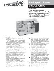
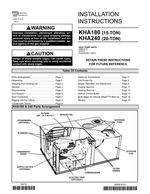
<strong>KHA</strong>180 & 240 DimensionsAA4−1/4(108)129−1/2 (3289)BASEBBALTERNATE (THRU THE BASE)CONDENSATE DRAIN LOCATION1−5/8 in. (41 mm) Diameter28−3/8(721)5−5/8 (143)12−3/8(314)12−3/8(314)60−1/2 (<strong>15</strong>37)<strong>15</strong> (381) BOTTOM RETURNAIR OPENINGBOTTOM SUPPLY18 (457) AIR OPENINGS28(711)<strong>20</strong> (508)28(711)4−1/2 <strong>20</strong> (508)(114)91−1/8 (23<strong>15</strong>)BASEEECENTER OFGRAVITYFFDD(4)1024 (102)BOTTOM POWER ENTRY127 X <strong>20</strong>3 mm (5 X 8 in.)TOP VIEWCC90−1/8(2289)128−1/2(3264)CONDENSATEDRAIN5−3/8(137)54−1/4(1378)51(1295)1/2(13)54−1/4(1378)29−1/4(743)SIDEELECTRICALINLETS91−1/8 (23<strong>15</strong>)BASE3−1/4(83)LIFTING HOLES(For RiggingFront and Back)129−1/2 (3289)BASEFORKLIFT SLOTS(Front and Left Sides Only)END VIEWSIDE VIEWShipping and Packing ListPackage 1 of 1 contains:1− Assembled unitCheck unit for shipping damage. Receiving party shouldcontact last carrier immediately if shipping damage is found.GeneralThese instructions are intended as a general guide anddo not supersede local codes in any way. Authoritieshaving jurisdiction should be consulted beforeinstallation.<strong>KHA</strong> units have <strong>15</strong>− and <strong>20</strong>−ton cooling capacities.Optional electric heat is available.Optional Multi−Stage Air Volume (MSAV TM ) units areavailable. The blower will operate at lower speeds whencooling demand is low and increase to higher speedswhen cooling demand is high. Refer to MSAV TMStart−Up section.Availability of units and options varies by brand.RequirementsThe <strong>KHA</strong> unit is ETL certified for outdoor installations onlyat the clearances to combustible materials listed on unitnameplate and in figure 1.<strong>Installation</strong> of <strong>KHA</strong> heat pumps must conform withstandards in National Fire Protection Association (NFPA)Standard for <strong>Installation</strong> of Air Conditioning andVentilating Systems NFPA No. 90A," Standard forPage 2 506916−01 1/<strong>20</strong>12
<strong>Installation</strong> of Residence Type Warm Air Heating and Airconditioning Systems NFPA No. 90B," local municipalbuilding codes and manufacturer’s installationinstructions.The National Electric Code (ANSI/NFPA No. 70−1984) isavailable from:National Fire Protection Association470 Atlantic AvenueBoston, MA 02210UNIT CLEARANCESThe <strong>KHA</strong> unit is ETL/CSA certified as a heat pump withcooling and with or without auxiliary electric heat fornon−residential use only at the clearances to combustiblematerials as listed on the unit nameplate and in figure 1.<strong>Installation</strong> of ETL/CSA certified units must conform withcurrent standard C273.5 <strong>Installation</strong> Requirements forHeat Pumps" and applicable local codes. Authoritieshaving jurisdiction should be consulted beforeinstallation.DOutdoorAir HoodCBUse of this unit as a construction heater or air conditioneris not recommended during any phase of construction.Very low return air temperatures, harmful vapors andoperation of the unit with clogged or misplaced filters willdamage the unit.AIf this unit has been used for heating or cooling ofbuildings or structures under construction, the followingconditions must be met or the warranty will be void:1 UnitClearanceAin.(mm)FIGURE 1Bin.(mm)Cin.(mm)Din.(mm)TopClearance A room thermostat must control the unit. The use offixed jumpers that will provide continuous heating orcooling is not allowed.ServiceClearanceMinimum OperationClearance45(1143)45(1143)36(914)36(914)36(914)36(914)66(1676)41(1041)UnobstructedUnobstructedNote − Entire perimeter of unit base requires support when elevated abovemounting surface.1 Service Clearance − Required for removal of serviceable parts.Minimum Operation Clearance − Required clearance for proper unit operation.WARNINGElectric shock hazard and danger ofexplosion. Can cause injury, death orproduct or property damage. Turn offgas and electrical power to unit beforeperforming any maintenance orservicing operations on the unit. Followlighting instructions attached to unitwhen putting unit back into operationand after service or maintenance.NOTICERoof Damage!This system contains both refrigerant and oil. Somerubber roofing material may absorb oil, causing therubber to swell. Bubbles in the rubber roofingmaterial can cause leaks. Protect the roof surfaceto avoid exposure to refrigerant and oil duringservice and installation. Failure to follow this noticecould result in damage to roof surface. A pre−filter must be installed at the entry to the returnair duct. The return air duct must be provided and sealed tothe unit. Return air temperature range between 55°F (13°C)and 80°F (27°C) must be maintained. Air filters must be replaced and pre−filter must beremoved upon construction completion. The unit components, duct system, air filters andevaporator coil must be thoroughly cleaned followingfinal construction clean−up. The unit operating conditions (including airflow,cooling operation, and heating operation) must beverified according to these installation instructions.IMPORTANTThe Clean Air Act of 1990 bans the intentional ventingof refrigerant (CFC’s and HCFC’s) as of July 1,1992. Approved methods of recovery, recycling orreclaiming must be followed. Fines and/or incarcerationmay be levied for non−compliance.<strong>KHA</strong>180, 240Page 3
Unit SupportNOTE − Securely fasten roof frame to roof per local codes.A−Downflow Discharge ApplicationRoof Mounting with LARMF18/361− The LARMF18/36 roof mounting frame must beinstalled, flashed and sealed in accordance with theinstructions provided with the frame.2− The LARMF18/36 roof mounting frame should besquare and level to 1/16" per linear foot (5mm perlinear meter) in any direction.3− Duct must be attached to the roof mounting frameand not to the <strong>KHA</strong> unit; supply and return plenumsmust be installed before setting the unit.4− Trim and discard any pieces of exposed insulation whichextend past the edges of the roof mounting frame.Installer’s Roof Mounting FrameMany types of roof frames can be used to install the <strong>KHA</strong>unit, depending upon different roof structures. Items tokeep in mind when using the building frame or supportsare:1− The <strong>KHA</strong> base is fully enclosed and insulated, so anenclosed frame is not required.2− The frames or supports must be constructed withnon−combustible materials and should be square andlevel to 1/16" per linear foot (5mm per linear meter)in any direction.3− Frame or supports must be high enough to prevent anyform of moisture from entering unit. Recommendedminimum frame height is 14" (356mm).4− Duct must be attached to the roof mounting frameand not to the <strong>KHA</strong> unit. Supply and return plenumsmust be installed before setting the unit.5− Units require support along all four sides of unit base.Supports must be constructed of steel or suitablytreated wood materials.NOTE−When installing an <strong>KHA</strong> unit on a combustiblesurface for downflow discharge applications, theLARMF18/36 roof mounting frame is required.3− Top of support slab should be at least 4" (102mm)above the finished grade and located so no run−offwater from higher ground can collect around the unit.4− Units require support along all four sides of unit base.Supports must be constructed of steel or suitablytreated wood materials.Duct ConnectionAll exterior ducts, joints, and openings in roof or buildingwalls must be insulated and weatherproofed with flashingand sealing compounds in accordance with applicablecodes. Any duct passing through an unconditioned spacemust be insulated.! CAUTIONIn downflow applications, do not drill or punchholes in base of unit. Leaking in roof may occur ifunit base is punctured.Rigging Unit For Lifting1− Detach wooden base protection before rigging.2− Connect rigging to the unit base using both holes ineach corner. See figure 2.3− All panels must be in place for rigging.4− Place field-provided H-style pick in place just abovetop edge of unit. Frame must be of adequatestrength and length. (H−style pick prevents damageto top of unit.)UNIT<strong>KHA</strong>180<strong>KHA</strong>240WEIGHT*LBS. KG.2350 10662635 1195*Maximum weight with allavailable accessories.CAUTION: DO NOTWALK ON UNIT.Lifting Point ShouldBe Directly AboveCenter Of Gravity.B−Horizontal Discharge Applications1− Units installed in horizontal airflow applications mustuse an LARMFH18/36 horizontal roof mountingframe. The supply air duct connects to the horizontalsupply air opening on the LARMFH18/36. The returnair duct connects to the unit horizontal return airopening. Refer to unit dimensions.2− Specified installation clearances must be maintainedwhen installing <strong>KHA</strong> units. Refer to figure 1.FIGURE 2Page 4 506916−01 1/<strong>20</strong>12
2− Install thermostat assembly in accordance withinstructions provided with thermostat.3− Connect thermostat wiring to TB1 terminal as shown infigure 5 for electro−mechanical and electronicthermostats. If using other temperature control devicesor energy management systems see instructions andwiring diagram provided by manufacturer.IMPORTANT−Terminal connections at the subbase andTB1 must be made securely. Loose control wireconnections may allow unit to operate but not with properresponse to room demand.24 VOLT FIELD WIRING WITH ELECTRONIC ANDELECTRO−MECHANICAL THERMOSTATSTB1Remove jumper between TB1−Rand TB1−OC when a night setbackthermostat is installed.Blower Operation And AdjustmentsA−Three Phase Scroll Compressor Voltage PhasingThree phase scroll compressors must be phasedsequentially to ensure correct compressor and blowerrotation and operation. Compressor and blower are wiredin phase at the factory. Power wires are color−coded asfollows: line 1−red, line 2−yellow, line 3−blue.1− Observe suction and discharge pressures andblower rotation on unit start−up.2− Suction pressure must drop, discharge pressuremust rise, and blower rotation must match rotationmarking.If pressure differential is not observed or blower rotation isnot correct:3− Disconnect all remote electrical power supplies.4− Reverse any two field−installed wires connected tothe line side of TB2. Do not reverse wires at blowercontactor.A2 THERMOSTATUnit Power−UpNOT ALL TERMINALSARE FOUND ON ALLTHERMOSTATSNote − On electro−mechanical thermostatsset anticipator at 0.1 amps.FIGURE 5A−General1− Make sure that unit is installed in accordance with theinstallation instructions and applicable codes.2− Inspect all electrical wiring, both field- andfactory-installed, for loose connections. Tighten asrequired.3− Check to ensure that refrigerant lines do not rubagainst the cabinet or against other refrigerant lines.4− Check voltage at disconnect switch. Voltage must bewithin range listed on nameplate. If not, consultpower company and have voltage conditioncorrected before starting unit.5− Make sure filters are in place before start-up.6− Apply power to unit.5− Make sure the connections are tight.Discharge and suction pressures should operate attheir normal start-up ranges.MSAV TM Units − All MSAV units are equipped with a phasemonitor located in the control compartment. The phasemonitor will detect the phasing of incoming power. If theincoming power is out of phase or if any of the three phasesare lost, the indicating LED on the phase monitor will turnred and the unit will not start. In normal operation withcorrect incoming power phasing, the LED will be green.B−Blower OperationInitiate blower demand at thermostat according toinstructions provided with thermostat. Unit will cycle onthermostat demand. The following steps apply toapplications using a typical electro−mechanicalthermostat.1− Set thermostat or temperature control device fanswitch to AUTO or ON. With fan switch in ON position,blower will operate continuously. With fan switch inAUTO position, the blower will cycle with demand.2− Blower and entire unit will be off when thermostat ortemperature control device system switch is in OFFposition.Page 6 506916−01 1/<strong>20</strong>12
C−Blower AccessD−Determining Unit CFMThe blower assembly is secured to a sliding base which IMPORTANT − MSAV TM units are factory−set to run theallows the entire assembly to be pulled out of the unit. See blower at full speed when there is a blower (G) demandfigure 6.without a heating or cooling demand. Use the following1− Remove the clamp which secures the blower wiring procedure to adjust motor pulley to deliver the full loadto the blower motor base.cooling or heating CFM. See MSAV TM Start−Up section toset blower CFM for all modes once the motor pulley is set.2− Remove and retain screws on either side of slidingbase. Pull base toward outside of unit. When pulling1− The following measurements must be made with athe base out further than 12" (305mm), disconnectdry indoor coil and with air filters in place. Run blowerwiring to K3 blower contactor T1, T2, and T3. Pullwithout a cooling demand. Measure the indoorwiring toward blower to allow enough slack to slideblower shaft RPM.the base out further.2− With all access panels in place, measure staticpressure external to unit (from supply to return).3− 3−Slide base back into original position whenBlower performance data is based on static pressurefinished servicing. Replace the clamp and blowerreadings taken in locations shown in figure 7.wiring in the previous location on the blower motorbase. Reconnect wiring to K3 if it was disconnected. Note − Static pressure readings can vary if not takenwhere shown.4− Replace retained screws on either side of the sliding3− Referring to page 10, use static pressure and RPMbase.readings to determine unit CFM. Use page 11 when5− Tighten two bolts on motor pulley side.installing units with any of the optional accessorieslisted.IMPORTANT − Align top edges of blower motor base and4− The blower RPM can be adjusted at the motor pulley.mounting frame base parallel before tightening two boltsLoosen Allen screw and turn adjustable pulleyon the other side of base. Motor shaft and blower shaftclockwise to increase CFM. Turn counterclockwise tomust be parallel.decrease CFM. See figure 6. Tighten Allen screw after6− Tighten two bolts on other side of base.adjustment. Do not exceed minimum and maximumnumber of pulley turns as shown in table 1.BLOWER ASSEMBLYTO INCREASE CFMLOOSEN ALLEN SCREW &TURN PULLEY CLOCKWISETO DECREASE CFMTURN PULLEYCOUNTERCLOCKWISETO INCREASE BELT TENSION1− Loosen four screws securing blower motor tosliding base.2− Turn adjusting screw to the left, or counterclockwise,to move the motor downward andtighten the belt.3− Tighten four screws.BELT TENSIONADJUSTINGSCREWSBLOWERWHEELBLOWER ASSEMBLYSLIDING BASEBLOWERMOTORLOOSEN (4) SCREWS TOADJUST BELT TENSIONALLENSCREWPULLEYFIGURE 6REMOVE SCREWS TOSLIDE BLOWERASSEMBLY OUT OF UNIT<strong>KHA</strong>180, 240Page 7
LOCATION OF STATIC PRESSURE READINGSINSTALLATIONS WITH DUCTWORKINSTALLATIONS WITH CEILING DIFFUSERSROOFTOP UNITROOFTOP UNITMAINDUCT RUNSUPPLYRE-TURNRETURN AIRREADING LOCATIONFIRST BRANCHOFF OF MAIN RUNSUPPLY AIRREADINGLOCATIONSUPPLY AIRREADINGLOCATIONSUPPLYRE-TURNDIFFUSERRETURN AIRREADINGLOCATIONTABLE 1MINIMUM AND MAXIMUM PULLEY ADJUSTMENTBeltMinimumTurns OpenMaximumTurns OpenA Section No minimum 5B Section 1* 6*No minimum number of turns open when B belt is used onpulleys 6" O.D. or larger.E−Blower Belt AdjustmentMaximum life and wear can be obtained from belts only ifproper pulley alignment and belt tension are maintained.Tension new belts after a 24−48 hour period of operation.This will allow belt to stretch and seat grooves. Make sureblower and motor pulley are aligned as shown in figure 8.MOTORPULLEYPULLEY ALIGNMENTALIGNEDBELTNOT ALIGNEDBLOWERPULLEYFIGURE 7F−Check Belt TensionOvertensioning belts shortens belt and bearing life.Check belt tension as follows:1− Measure span length X. See figure 9.2− Apply perpendicular force to center of span (X) withenough pressure to deflect belt 1/64" for every inchof span length or 1.5mm per 100mm of span length.Example: Deflection distance of a 40" span would be40/64" or 5/8".Example: Deflection distance of a 400mm spanwould be 6mm.3− Measure belt deflection force. For a used belt, thedeflection force should be 5 lbs. (35kPa) . A new beltdeflection force should be 7 lbs. (48kPa).A force below these values indicates andundertensioned belt. A force above these valuesindicates an overtensioned belt.MEASURE BELT TENSIONFIGURE 81− Loosen four screws securing blower motor to slidingbase. See figure 6.2− To increase belt tension −Turn belt tension adjusting screw to the left, orcounterclockwise, to tighten the belt. This increasesthe distance between the blower motor and theblower housing.To loosen belt tension −Turn the adjusting screw to the right, or clockwise toloosen belt tension.FORCEDEFLECTION 1/64" PER INCH OF SPANOR 1.5mm PER 100mm OF SPANFIGURE 9G−Field−Furnished Blower DrivesFor field−furnished blower drives, use pages 9 and 10 todetermine BHP and RPM required. Reference page 10to determine the drive number and table 2 to determinethe manufacturer’s model number.Page 8 506916−01 1/<strong>20</strong>12
BLOWER DATABLOWER TABLE INCLUDES RESISTANCE FOR BASE UNIT ONLY WITH DRY INDOOR COIL & AIR FILTERS IN PLACEFOR ALL UNITS ADD:1 - Wet indoor coil air resistance of selected unit.2 - Any factory installed options air resistance (electric heat, economizer, etc.)3 - Any field installed accessories air resistance (electric heat, duct resistance, diffuser, etc.)Then determine from blower table blower motor output and drive required.See page 10 for wet coil and option/accessory air resistance data.See page 10 for factory installed drive kit specifications.MINIMUM AIR VOLUME REQUIRED FOR USE WITH OPTIONAL ELECTRIC HEATAll units require 6000 cfm minimum air with electric heat.AirTOTAL STATIC PRESSURE - Inches Water Gauge (Pa)Volume 0.<strong>20</strong> 0.40 0.60 0.80 1.00 1.<strong>20</strong> 1.40 1.60 1.80 2.00 2.<strong>20</strong> 2.40 2.60cfmRPM BHP RPM BHP RPM BHP RPM BHP RPM BHP RPM BHP RPM BHP RPM BHP RPM BHP RPM BHP RPM BHP RPM BHP RPM BHP3250 405 0.40 5<strong>20</strong> 0.60 6<strong>15</strong> 0.85 695 1.10 765 1.30 830 1.60 890 1.85 950 2.10 - - - - - - - - - - - - - - - - - - - - - - - - - - - - - -3500 4<strong>15</strong> 0.45 530 0.70 6<strong>20</strong> 0.95 700 1.<strong>20</strong> 775 1.45 840 1.70 900 2.00 955 2.25 1005 2.55 - - - - - - - - - - - - - - - - - - - - - - - -3750 425 0.50 540 0.75 630 1.05 710 1.30 780 1.60 845 1.85 905 2.<strong>15</strong> 960 2.45 1010 2.70 1060 3.00 1110 3.30 - - - - - - - - - - - -4000 435 0.55 545 0.85 635 1.10 7<strong>15</strong> 1.40 785 1.70 850 2.00 910 2.30 965 2.60 10<strong>20</strong> 2.90 1070 3.25 11<strong>15</strong> 3.55 1160 3.85 1<strong>20</strong>5 4.<strong>15</strong>4250 445 0.60 555 0.90 645 1.25 725 1.55 795 1.85 855 2.<strong>15</strong> 9<strong>15</strong> 2.45 970 2.80 1025 3.10 1075 3.45 11<strong>20</strong> 3.75 1165 4.10 1210 4.454500 455 0.70 565 1.00 655 1.35 730 1.65 800 2.00 865 2.35 925 2.65 980 3.00 1030 3.30 1080 3.65 1130 4.05 1175 4.35 12<strong>15</strong> 4.704750 470 0.75 575 1.10 660 1.45 740 1.80 810 2.<strong>15</strong> 870 2.50 930 2.85 985 3.<strong>20</strong> 1040 3.55 1085 3.90 1135 4.25 1180 4.65 1225 5.005000 480 0.85 585 1.25 670 1.60 750 1.95 8<strong>15</strong> 2.30 880 2.70 940 3.05 995 3.40 1045 3.80 1095 4.<strong>15</strong> 1140 4.50 1185 4.90 1230 5.305250 495 0.95 595 1.35 680 1.70 755 2.10 825 2.50 890 2.90 945 3.25 1000 3.65 1050 4.00 1100 4.40 1<strong>15</strong>0 4.80 1195 5.<strong>20</strong> 1235 5.605500 505 1.05 605 1.45 690 1.85 765 2.25 835 2.65 895 3.05 955 3.45 1010 3.85 1060 4.25 1110 4.70 1<strong>15</strong>5 5.10 1<strong>20</strong>0 5.50 1240 5.905750 5<strong>20</strong> 1.<strong>15</strong> 6<strong>15</strong> 1.60 700 2.00 775 2.45 840 2.85 905 3.25 960 3.65 10<strong>15</strong> 4.10 1065 4.50 11<strong>15</strong> 4.95 1160 5.35 1<strong>20</strong>5 5.80 1250 6.256000 530 1.30 630 1.75 710 2.<strong>15</strong> 785 2.60 850 3.05 910 3.45 970 3.90 1025 4.35 1075 4.80 11<strong>20</strong> 5.<strong>20</strong> 1170 5.65 12<strong>15</strong> 6.10 1255 6.556250 545 1.40 640 1.90 7<strong>20</strong> 2.35 795 2.80 860 3.25 9<strong>20</strong> 3.70 975 4.<strong>15</strong> 1030 4.60 1080 5.05 1130 5.50 1175 5.95 12<strong>20</strong> 6.45 1265 6.906500 560 1.55 650 2.05 730 2.50 805 3.00 870 3.45 930 3.95 985 4.40 1040 4.85 1090 5.35 1140 5.85 1185 6.30 1225 6.75 1270 7.256750 570 1.70 665 2.<strong>20</strong> 745 2.70 8<strong>15</strong> 3.<strong>20</strong> 880 3.70 940 4.<strong>20</strong> 995 4.65 1045 5.10 1095 5.60 1145 6.10 1190 6.60 1235 7.10 1275 7.607000 585 1.85 675 2.35 755 2.90 825 3.40 890 3.95 950 4.45 1005 4.95 1055 5.40 1105 5.95 1<strong>15</strong>5 6.45 1<strong>20</strong>0 6.95 1240 7.45 1285 8.007250 600 2.00 690 2.60 765 3.10 835 3.65 900 4.<strong>15</strong> 955 4.65 10<strong>15</strong> 5.25 1065 5.75 11<strong>15</strong> 6.25 1160 6.75 1<strong>20</strong>5 7.30 1250 7.85 1290 8.357500 6<strong>15</strong> 2.<strong>20</strong> 700 2.75 775 3.30 845 3.85 910 4.45 965 4.95 10<strong>20</strong> 5.50 1075 6.05 1125 6.60 1170 7.<strong>15</strong> 12<strong>15</strong> 7.65 1260 8.25 1300 8.757750 630 2.40 7<strong>15</strong> 3.00 790 3.55 855 4.10 9<strong>20</strong> 4.70 975 5.25 1030 5.80 1080 6.35 1130 6.90 1180 7.50 1225 8.05 1265 8.60 1305 9.<strong>15</strong>8000 640 2.55 725 3.<strong>20</strong> 800 3.80 865 4.35 930 4.95 985 5.50 1040 6.10 1090 6.70 1140 7.25 1185 7.85 1230 8.40 1275 9.00 13<strong>15</strong> 9.608250 655 2.80 740 3.40 810 4.00 880 4.65 940 5.25 995 5.85 1050 6.45 1100 7.05 1<strong>15</strong>0 7.65 1195 8.25 1240 8.85 1280 9.40 1325 10.058500 670 3.00 750 3.65 825 4.30 890 4.90 950 5.55 1005 6.<strong>15</strong> 1060 6.80 1110 7.40 1160 8.05 1<strong>20</strong>5 8.65 1250 9.25 1290 9.85 1330 10.458750 685 3.25 765 3.90 835 4.55 900 5.<strong>20</strong> 960 5.85 10<strong>15</strong> 6.45 1070 7.<strong>15</strong> 11<strong>20</strong> 7.75 1165 8.35 12<strong>15</strong> 9.05 1255 9.65 1300 10.30 1340 10.909000 700 3.50 780 4.<strong>20</strong> 850 4.85 910 5.50 970 6.<strong>15</strong> 1025 6.80 1080 7.50 1130 8.<strong>15</strong> 1175 8.75 12<strong>20</strong> 9.40 1265 10.10 1310 10.80 1350 11.409250 7<strong>15</strong> 3.75 790 4.45 860 5.<strong>15</strong> 925 5.85 985 6.55 1040 7.<strong>20</strong> 1090 7.85 1140 8.55 1185 9.<strong>20</strong> 1230 9.85 1275 10.55 13<strong>15</strong> 11.<strong>20</strong> - - - - - -9500 730 4.00 805 4.75 875 5.45 935 6.<strong>15</strong> 995 6.90 1050 7.60 1100 8.25 1<strong>15</strong>0 8.95 1195 9.60 1240 10.30 1285 11.05 - - - - - - - - - - - -9750 745 4.30 8<strong>20</strong> 5.05 885 5.75 950 6.55 1005 7.<strong>20</strong> 1060 7.95 1110 8.65 1160 9.40 1<strong>20</strong>5 10.05 1250 10.80 1295 11.50 - - - - - - - - - - - -10,000 760 4.60 835 5.40 900 6.<strong>15</strong> 960 6.85 10<strong>15</strong> 7.60 1070 8.35 11<strong>20</strong> 9.05 1170 9.80 12<strong>15</strong> 10.50 1260 11.25 - - - - - - - - - - - - - - - - - -10,250 775 4.90 845 5.65 910 6.45 970 7.<strong>20</strong> 1030 8.00 1080 8.75 1135 9.55 1180 10.25 1225 11.00 - - - - - - - - - - - - - - - - - - - - - - - -10,500 790 5.<strong>20</strong> 860 6.00 925 6.85 985 7.65 1040 8.40 1095 9.<strong>20</strong> 1145 10.00 1190 10.70 1235 11.45 - - - - - - - - - - - - - - - - - - - - - - - -10,750 805 5.55 875 6.40 940 7.25 1000 8.05 1055 8.85 1105 9.65 1<strong>15</strong>5 10.45 1<strong>20</strong>0 11.<strong>20</strong> - - - - - - - - - - - - - - - - - - - - - - - - - - - - - -11,000 8<strong>20</strong> 5.90 890 6.80 950 7.60 1010 8.45 1065 9.30 11<strong>15</strong> 10.05 1165 10.90 - - - - - - - - - - - - - - - - - - - - - - - - - - - - - - - - - - - -Page 9
BLOWER DATAFACTORY INSTALLED BELT DRIVE KIT SPECIFICATIONSNominalhpMaximumhpDrive Kit NumberRPM Range3 3.45 1 535 - 7253 3.45 2 710 - 9655 5.75 3 685 - 8565 5.75 4 850 - 10455 5.75 5 945 - 11857.5 8.63 6 850 - 10457.5 8.63 7 945 - 11857.5 8.63 8 1045 - 128510 11.50 7 945 - 118510 11.50 10 1045 - 128510 11.50 11 1135 - 1365NOTE - Using total air volume and system static pressure requirements determine from blower performance tables rpm and motor output required. Maximum usableoutput of motors furnished are shown. In Canada, nominal motor output is also maximum usable motor output. If motors of comparable output are used, be sure to keepwithin the service factor limitations outlined on the motor nameplate.FACTORY INSTALLED OPTIONS/FIELD INSTALLED ACCESSORY AIR RESISTANCE - in. w.g.HorizontalAir Volume Wet Indoor CoilEconoFiltersElectric HeatRoof Curbcfmmizer180S 240S MERV 8 MERV 13 180S, 240S3250 0.01 0.03 - - - - - - 0.01 0.04 0.043500 0.01 0.03 - - - - - - 0.01 0.04 0.053750 0.01 0.03 - - - - - - 0.01 0.04 0.054000 0.02 0.04 - - - - - - 0.01 0.04 0.064250 0.02 0.04 - - - - - - 0.01 0.05 0.074500 0.02 0.05 - - - - - - 0.01 0.05 0.074750 0.02 0.05 - - - - - - 0.02 0.05 0.085000 0.02 0.05 - - - - - - 0.02 0.06 0.085250 0.02 0.06 - - - - - - 0.02 0.06 0.095500 0.02 0.07 - - - - - - 0.02 0.06 0.105750 0.03 0.07 - - - - - - 0.02 0.07 0.116000 0.03 0.08 0.01 - - - 0.03 0.07 0.116250 0.03 0.08 0.01 0.01 0.03 0.07 0.126500 0.03 0.09 0.01 0.02 0.03 0.08 0.136750 0.04 0.10 0.01 0.03 0.03 0.08 0.147000 0.04 0.10 0.01 0.04 0.04 0.08 0.<strong>15</strong>7250 0.04 0.11 0.01 0.05 0.04 0.09 0.167500 0.05 0.12 0.01 0.06 0.04 0.09 0.178000 0.05 0.13 0.02 0.09 0.05 0.10 0.198500 0.06 0.<strong>15</strong> 0.02 0.11 0.05 0.10 0.219000 0.07 0.16 0.04 0.14 0.06 0.11 0.249500 0.08 0.18 0.05 0.16 0.07 0.12 0.2610,000 0.08 0.<strong>20</strong> 0.06 0.19 0.07 0.12 0.2910,500 0.09 0.22 0.09 0.22 0.08 0.13 0.3111,000 0.11 0.24 0.11 0.25 0.09 0.14 0.34Page 10
DriveNo.H.P.TABLE 2MANUFACTURER’S NUMBERSDRIVE COMPONENTSRPM ADJUSTABLE SHEAVE FIXED SHEAVE BELTS SPLIT BUSHINGMin Max Supplier No.OEM PartNo.Supplier No.OEM PartNo.SupplierNo.OEM PartNo.SupplierNo.1 3 535 725 1VP40x7/8 79J0301 BK95X1−7/16 80K1601 BX59 59A5001 N/A N/A2 3 710 965 1VP40x7/8 79J0301 BK72x1-7/16 100244−13 BX56 63K0501 N/A N/A3 5 685 865 1VP50x1−1/8 P−8−1977 BK100x1-7/16 39L1301 BX61 93J9801 N/A N/AOEM PartNo.4 5 850 1045 1VP65x1−1/8 100239−03 BK110H 100788−06 BX65 100245−08 H−1−7/16 49M6<strong>20</strong><strong>15</strong> 5 945 1185 1VP60x1−1/8 41C1301 BK90H 100788−04 BX61 93J9801 H−1−7/16 49M6<strong>20</strong>16 7.5 850 1045 1VP65x1−3/8 78M7101 BK110H 100788−06 BX66 97J5901 H−1−7/16 49M6<strong>20</strong>17 7.5, 10 945 1185 1VP60x1−3/8 78L5501 BK90H 100788−04 BX63 97J5501 H−1−7/16 49M6<strong>20</strong>18 7.5 1045 1285 1VP65x1−3/8 78M7101 BK90H 100788−04 BX64 97J5801 H−1−7/16 49M6<strong>20</strong>110 10 1045 1285 1VP65x1−3/8 78M7101 1B5V86 78M8301 5VX670 100245−21 B−1−7/16 100246−0111 10 1135 1365 1VP65x1−3/8 78M7101 1B5V80 100240−05 5VX660 100245−<strong>20</strong> B−1−7/16 100246−01Cooling Start−UpA−Start−UpMSAV TM Units − Refer to the MSAV TM Start−Up section.180 & 240 REFRIGERANT CIRCUITSOUTDOOR COIL 11− Remove coil covers before starting unit.2− Set thermostat or temperature control device fanswitch to AUTO or ON. Set thermostat or temperaturecontrol device to initiate a first−stage cooling demand.INDOOR COILCOND.FAN 2COND.FAN 1A first−stage (Y1) cooling demand will energizecompressor 1 and outdoor fans 1 & 2. An increasedcooling demand (Y2) will initiate compressor 2 andoutdoor fans 3 & 4. On units with an economizer,when outdoor air is acceptable, a first−stagedemand will energize the economizer; asecond−stage demand will energize compressor 1and outdoor fans 1 & 2.3− Refrigerant circuits are factory charged with R−410Arefrigerant. See unit rating plate for correct amount ofcharge.4− Units contain two refrigerant circuits or systems. Seefigure 10.B−Refrigerant Charge and CheckWARNING−Do not exceed nameplate charge under any condition.This unit is factory charged and should require no furtheradjustment. If the system requires additional refrigerant,reclaim the charge, evacuate the system, and addrequired nameplate charge.NOTE − System charging is not recommended below60°F (<strong>15</strong>°C). In temperatures below 60°F (<strong>15</strong>°C), thecharge must be weighed into the system.If weighing facilities are not available, or to check thecharge, use the following procedure:BLOWERBLOWERCOMPRESSOR 1 COMPRESSOR 2 OUTDOORCOIL 2FIGURE 10COND.FAN 4COND.FAN 31− Attach gauge manifolds and operate unit in coolingmode with economizer disabled until systemstabilizes (approximately five minutes). Make sure alloutdoor air dampers are closed.2− Check each system separately with all stagesoperating.3− Use a thermometer to accurately measure theoutdoor ambient temperature.4− Apply the outdoor temperature to table 3 or 4 todetermine normal operating pressures. Pressuresare listed for sea level applications at 80F dry bulband 67F wet bulb return air.5− Compare the normal operating pressures to thepressures obtained from the gauges. Minorvariations in these pressures may be expected due to<strong>KHA</strong>180, 240Page 11
differences in installations. Significant differencescould mean that the system is not properly chargedor that a problem exists with some component in thesystem. Correct any system problems beforeproceeding.6− If discharge pressure is high, remove refrigerant fromthe system. If discharge pressure is low, addrefrigerant to the system. Add or remove charge in increments. Allow the system to stabilize each timerefrigerant is added or removed.7− Use the following approach method along with thenormal operating pressures to confirm readings.TABLE 3<strong>KHA</strong>180 NORMAL OPERATING PRESSURESOutdoorCoil EnteringAir TempDis. +10psigCircuit 1 Circuit 2Suc. +5psigDis. +10psigSuc. +5psig65F 270 138 270 13575F 312 139 312 13585F 356 142 356 13695F 403 144 404 138105F 455 147 458 1401<strong>15</strong>F 512 147 5<strong>15</strong> 145TABLE 4<strong>KHA</strong>240 NORMAL OPERATING PRESSURESOutdoorCoil EnteringAir TempDis. +10psigCircuit 1 Circuit 2Suc. +5psigDis. +10psigSuc. +5psig65F 275 135 278 13575F 3<strong>15</strong> 138 318 13685F 359 140 364 13895F 407 142 413 140105F 457 144 466 1411<strong>15</strong>F 517 146 527 145C−Charge Verification − Approach Method − AHRI Testing1− Using the same thermometer, compare liquidtemperature to outdoor ambient temperature.Approach Temperature = Liquid temperature (atcondenser outlet) minus ambient temperature.2− Approach temperature should match values in table5. An approach temperature greater than valueshown indicates an undercharge. An approachtemperature less than value shown indicates anovercharge.3− The approach method is not valid for grossly over orundercharged systems. Use table 3 or 4 as a guidefor typical operating pressures.Unit180 & 240TABLE 5APPROACH TEMPERATURESLiquid Temp. Minus Ambient Temp.1st Stage2nd Stage12°F + 1(6.7°C + 0.5)12°F + 1(6.7°C + 0.5)D−Compressor Controls1− High Pressure Switches (S4, S7)Compressor circuits are protected by a high pressureswitch which cuts out at 640 psig + 10 psig (4413 kPa+ 70 kPa).2− Freezestats (S49, S50)Switches de−energize compressors when indoor coiltemperature falls below 29F (−2C) to prevent coilfreeze−up. Switches reset when indoor coiltemperature reaches 58F (<strong>15</strong>C).3− Defrost Switches (S6, S9)Defrost switches close to initiate defrost when liquidline temperature falls to 35F (1.7C). The defrostswitch is located on the liquid line between theoutdoor expansion valve and the distributor4− Defrost Termination Switches (S46, S104)Defrost pressure switches open to terminate defrostwhen vapor line (discharge pressure during coolingand defrost) pressure reaches 450 psig (3103 kPa).5− Defrost Controls (CMC1, CMC2)Defrost is liquid line temperature initiated andoperates for 14 minutes unless terminated by vaporline pressure drop.When the liquid line temperature drops below 35°F,the defrost switch closes and signals the defrostcontrol that a defrost cycle is needed. If the defrostswitch is still closed after 60 minutes (default), adefrost cycle begins and operates for 14 minutes.The defrost pressure switch can terminate the defrostcycle before the 14 minutes elapses if vapor linepressure reaches 450 + 10 psi.6− Electric heat is energized during defrost to maintaindischarge air temperature.Heating Start−Up1− Set thermostat or temperature control device toinitiate a first−stage heating demand.A first−stage heating demand (W1) will energizecompressors 1 and 2. All four outdoor fans areenergized with a W1 demand.<strong>KHA</strong> Units With Optional Electric Heat −An increased heating demand (W2) will energizeelectric heat.Page 12 506916−01 1/<strong>20</strong>12
Defrost Control BoardThe defrost thermostat, defrost pressure switch and thedefrost control work together to ensure that the heatpump outdoor coil does not ice excessively during theheating mode.Compressor Accumulated Run−Time IntervalThe defrost control will not energize a defrost cycle unlessthe unit has been operating in heating mode for anaccumulated 60 minutes (default) on 100269−02 boards;90 minutes (default) on 100269−04 boards. The run timeinterval can be changed by moving the jumper on theCMC board timing pins. See figure 11.The defrost interval can be adjusted to 30, 60, or 90minutes. The defrost timing jumper is factory−installed toprovide a 60−minute defrost interval. If the timing selectorjumper is not in place, the control defaults to a 90−minutedefrost interval.Note − When adjusting timing pins, set both CMC1 andCMC2 defrost controls to the same defrost interval.Defrost Test OptionA TEST option is provided for troubleshooting. The TESTmode may be started any time the unit is in the heatingmode and the defrost thermostat is closed or jumpered. Ifthe timing jumper is in the TEST position at power-up, thedefrost control will ignore the test pins. When the jumperis placed across the TEST pins for two seconds, thecontrol will enter the defrost mode. If the jumper isremoved before an additional 5−second period haselapsed (7 seconds total), the unit will remain in defrostmode until the defrost pressure switch opens or 14minutes have passed. If the jumper is not removed untilafter the additional 5−second period has elapsed, thedefrost will terminate and the test option will not functionagain until the jumper is removed and re−applied.Diagnostic LEDsThe defrost board uses two LEDs for diagnostics. TheLEDs flash a sequence according to the condition.TABLE 6Defrost Control Board Diagnostic LEDIndicates LED 1 LED 2Normal operation /power to boardBoard failure /no powerSynchronizedFlash with LED 2OffSynchronizedFlash with LED 1OffBoard failure On OnPressure switch open Flash OnDEFROST CONTROL BOARD CMC1 AND CMC2TIMING JUMPER100269−02: 60 MINUTES100269−04: 90 MINUTESDIAGNOSTICLEDS100269−02:INSTALLED ATTHE FACTORY TO DISABLECOMPRESSOR DELAY100269−04:REMOVED ATTHE FACTORY TO DISABLECOMPRESSOR DELAYFIGURE 11<strong>KHA</strong>180, 240Page 13
MSAV TM Start−UpA−GeneralOptional Multi−Stage Air Volume (MSAV TM ) units areavailable which provide two blower speeds. The blowerwill operate at lower speeds when cooling demand is lowand higher speeds when cooling demand is high. Thisresults in lower energy consumption.MSAV TM units will operate at high speed duringventilation (blower G" only signal) but can be adjusted tooperate at low speed.Low speed is approximately 2/3 of the full speed RPM.B−Set Maximum Blower CFM1. Initiate a blower (G) only signal from the roomthermostat or control system.2. Adjust the blower pulley to deliver the full (highspeed) CFM in the typical manner. See DeterminingUnit CFM in the Blower Operation and Adjustmentsection.C−Set Blower Speed During VentilationTo save energy during ventilation, the blower speed canbe set to low. This is accomplished by changing theventilation speed switch on the VFD control board to LO".See figure 12.Note − On units equipped with an economizer, set damperminimum position as shown in the next section. Afteradjusting the low speed minimum position, the ventilationspeed switch will be in the LO" position.D−Set Damper Minimum Position (Units W/ Economizer)To maintain required minimum ventilation air volumeswhen the unit is in the occupied mode, two minimumdamper positions must be set. A high and a low speedpotentiometer are provided on the VFD control board toadjust minimum damper position. See figure 12.Set High Speed Minimum Position1. Initiate a blower (G) only AND occupied demand fromthe room thermostat or control system.2. Set the ventilation speed switch on the VFD controlboard to HI".3. Rotate the high speed potentiometer on the VFDcontrol board to set the high speed minimum damperposition.4. Measure the intake air CFM. If the CFM is lower thanthe design specified CFM for ventilation air, use thepotentiometer to increase the damper percent open.If the CFM is higher than specified, decrease thedamper percent open.Note − Intake air CFM can also be determined using theoutdoor air temperature, return air temperature andmixed air temperature. Refer to the economizer oroutdoor air damper installation instructions.Set Low Speed Minimum Position1. Initiate a blower (G) only AND occupied demand fromthe room thermostat or control system.2. Set the ventilation speed switch on the VFD controlboard to LO".3. Rotate the low speed potentiometer on the VFDcontrol board to set the low speed minimum damperposition.4. Measure the intake air CFM. If the CFM is lower thanthe design specified CFM for ventilation air, use thepotentiometer to increase the damper percent open.If the CFM is higher than specified, decrease thedamper percent open.Note − Intake air CFM can also be determined using theoutdoor air temperature, return air temperature andmixed air temperature. Refer to the economizer oroutdoor air damper installation instructions.LVC2 (A183) VFD CONTROL BOARDVENTILATIONSPEED SWITCHPOWERLEDLOW SPEEDMINIMUM POSITIONPOTENTIOMETERHIGH SPEEDMINIMUM POSITIONPOTENTIOMETERFIGURE 12Troubleshoot LVC2 Board (A183)Refer to wiring diagram sections B (unit), C (control) andD (economizer) located on inside of unit panels.1. Inspect the LVC2 for damaged components. Replacethe LVC2 if damaged components are found.2. Check all wire connections to LVC2; secure if loose.3. Check for 24VAC signal at the thermostat blowerinput (G to GND terminal). See figure 13.Page 14 506916−01 1/<strong>20</strong>12
LVC2 BOARD TERMINAL DESIGNATIONSService24VDCVFD INPUTS;H2 HEADERFIGURE 1324VACTHERMOSTAT INPUTS;H1 HEADER4. If there is no thermostat signal, troubleshoot backtoward the thermostat.5. Check the power LED on the board. See figure 12.6. If the power LED is not on, check voltage betweenLVC2 terminals PC (H2−1) and SD (H2−5). Voltageshould read 24VDC.7. If voltage does not read 24VDC, disconnect the H2header from the LVC2 VFD inputs terminal block (tomake sure the LVC2 is not shorting 24VDC supplyfrom the inverter). Measure the voltage between theend terminals on the H2 header. If 24VDC is present,replace the LVC2 board. If no voltage is read,troubleshoot the VFD.8. When LVC2 24VAC thermostat blower (G) input and24VDC power are present, check the LVC2 low andhigh speed outputs. The LVC2 uses inverse logic toenable the blower; 1VDC will be read at the enabledblower speed terminal. See table 7.9. If all inputs are correct and the unit still does notoperate as intended, replace LVC2 board.OutputTerminalsRL−SDRH−SDRL−SDRH−SDRL−SDRH−SDTABLE 7LVC2 BOARD BLOWER OUTPUTSVoltage1VDC24VDC24VDC1VDC1VDC1VDCBlower OperationLow SpeedHigh SpeedIllegal State(replace board)CAUTIONLabel all wires prior to disconnection when servicingcontrols. Wiring errors can cause improper anddangerous operation. Verify proper operation afterservicing.WARNINGProduct contains fiberglass wool.Disturbing the insulation in this product duringinstallation, maintenance, or repair will expose youto fiberglass wool. Breathing this may cause lungcancer. (Fiberglass wool is known to the State ofCalifornia to cause cancer.)Fiberglass wool may also cause respiratory, skin,and eye irritation.To reduce exposure to this substance or for furtherinformation, consult material safety data sheetsavailable from address shown below, or contactyour supervisor.P.O. Box 799900Dallas, TX 75379−9900The unit should be inspected once a year by a qualifiedservice technician.A−LubricationAll motors are lubricated at the factory. No furtherlubrication is required.Blower shaft bearings are prelubricated. For extendedbearing life, relubricate at least once every two years witha lithium base grease, such as Alvania 3 (Shell Oil),Chevron BRB2 (Standard Oil) or Regal AFB2 (Texas Oil).Use a hand grease gun for relubrication. Add only enoughgrease to purge through the bearings so that a bead ofgrease appears at the seal lip contacts.B−FiltersUnits are equipped with six 24 X 24 X 2" filters. Filtersshould be checked and replaced when necessary withfilters of like kind and size. Take note of air flow directionmarking on filter frame when reinstalling filters. Seefigure 14.RL−SDRH−SD24VDC24VDCBlower Off(replace board)NOTE−Filters must be U.L.C. certified or equivalent foruse in Canada.<strong>KHA</strong>180, 240Page <strong>15</strong>
REMOVE FILTERSC−Indoor CoilInspect and clean coil at beginning of each cooling andheating season. Clean using mild detergent orcommercial coil cleaner. Flush coil and condensate drainwith water taking care not to get insulation, filters andreturn air ducts wet.PULL TOREMOVEFILTERSD−Outdoor CoilClean outdoor coil annually with detergent or commercialcoil cleaner and inspect monthly during the cooling season.Outdoor coils are made of two formed slabs. Dirt anddebris may become trapped between the slabs. To cleanbetween slabs, carefully separate coil slabs and washthem thoroughly. See figure <strong>15</strong>. Flush coils with waterfollowing cleaning.Note − Remove all screws and gaskets prior to cleaningprocedure and replace upon completion.FIGURE 14E−Supply Air Blower WheelAnnually inspect supply air blower wheel for accumulateddirt or dust. Turn off power before attempting to removeaccess panel or to clean blower wheel.INDOOR COILEND PLATE ISSECURED TOMULLIONTOP VIEWEND PLATE ISSECURED TOMULLIONCLEAN CONDENSER COILOUTDOORCOILOUTDOORCOIL ACCESSPANELOUTDOORCOIL1− Remove unit outdoor section top panel and outdoorcoil access panel.2− Remove screws securing coil end plates to mullions.3− Remove wire ties connecting coils slabs and separateslabs 3−4" (76−102mm).4− Clean coils with detergent or commercial coil cleaner.5− Rinse thoroughly with water and reassemble.6− Secure coil slabs together using field−providedwire ties.FIGURE <strong>15</strong>Page 16 506916−01 1/<strong>20</strong>12