User Manual - Mitsubishi Electric Sales Canada Inc.
User Manual - Mitsubishi Electric Sales Canada Inc.
User Manual - Mitsubishi Electric Sales Canada Inc.
You also want an ePaper? Increase the reach of your titles
YUMPU automatically turns print PDFs into web optimized ePapers that Google loves.
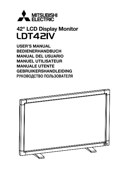
42" LCD Display MonitorUSER’S MANUALBEDIENERHANDBUCHMANUAL DEL USUARIOMANUEL UTILISATEURMANUALE UTENTEGEBRUIKERSHANDLEIDINGРУКОВОДСТВО ПОЛЬЗОВАТЕЛЯ
IndexImportant Information ...................................................................................................................................Safety Precautions, Maintenance & Recommended Use ...........................................................................Contents .......................................................................................................................................................Parts Name and Functions ..........................................................................................................................Control Panel ..................................................................................................................................Terminal Panel .................................................................................................................................Wireless Remote Control ...............................................................................................................Operating Range for the Remote Control .......................................................................................Handling the remote control ...........................................................................................................Setup Procedure ..........................................................................................................................................How to Mount and Attach Options to the LCD Monitor ...............................................................................Connections .................................................................................................................................................Wiring Diagram ...............................................................................................................................Connecting a Personal Computer ..................................................................................................Connecting with Digital Interface Equipment ................................................................................Connecting a DVD Player with component out ..............................................................................Connecting to a Stereo Amplifier ....................................................................................................Basic Operation ............................................................................................................................................Power ON and OFF Modes ............................................................................................................Power Indicator ...............................................................................................................................Using Power Management ............................................................................................................Selecting a video source ................................................................................................................Picture Size ....................................................................................................................................Picture Mode ..................................................................................................................................Audio Source Switching .................................................................................................................Information OSD .............................................................................................................................OSD (On-Screen-Display) Controls ..............................................................................................................PICTURE .........................................................................................................................................SCREEN ..........................................................................................................................................AUDIO .............................................................................................................................................PICTURE IN PICTURE ....................................................................................................................CONFIGURATION 1 ........................................................................................................................CONFIGURATION 2 ........................................................................................................................ADVANCED OPTION ......................................................................................................................NOTE ..............................................................................................................................................Controlling the LCD monitor via RS-232C Remote Control ........................................................................Features ........................................................................................................................................................Troubleshooting ............................................................................................................................................Specifications ..............................................................................................................................................Pin Assignment ............................................................................................................................................English-2English-4English-5English-6English-6English-7English-8English-9English-9English-10English-13English-14English-14English-15English-16English-17English-18English-19English-19English-20English-20English-20English-20English-20English-20English-21English-22English-23English-24English-25English-25English-26English-27English-28English-30English-32English-34English-35English-37English-38EnglishEnglish-1
Important InformationDECLARATION OF CONFORMITYThis device complies with Part 15 of FCC Rules. Operation is subject to the following two conditions. (1) This device maynot cause harmful interference, and (2) this device must accept any interference received, including interference that maycause undesired operation.U.S. Responsible Party: <strong>Mitsubishi</strong> Digital Electronics America, <strong>Inc</strong>.Address:9351 Jeronimo Road,Irvine, California 92618 U.S.A.Tel. No.: +1 - (949) 465-6000Type of Product: Computer MonitorEquipment Classification: Class B PeripheralModel:LDT421V (LR617)We hereby declare that the equipment specified aboveconforms to the technical standards as specified in the FCC Rules.Windows is a registered trademark of Microsoft Corporation. All other brands and product names are trademarks or registeredtrademarks of their respective owners.HDMI, the HDMI logo and High-Definition Multimedia Interface are trademarks or registered trademarks of HDMILicensing LLC.Canadian Department of Communications Compliance StatementDOC: This Class B digital apparatus meets all requirements of the Canadian Interference-Causing Equipment Regulations.C-UL: Bears the C-UL Mark and is in compliance with Canadian Safety Regulations according to CAN/CSA C22.2 No.60950-1.FCC Information1. Use the attached specified cables with the LDT421V (LR617) color monitor so as not to interfere with radio and televisionreception.(1) Please use the supplied power cord or equivalent to ensure FCC compliance.(2) Please use the supplied shielded video signal cable, 15-pin mini D-SUB to 15-pin mini D-SUB.2. This equipment has been tested and found to comply with the limits for a Class B digital device, pursuant to part 15 of theFCC Rules.These limits are designed to provide reasonable protection against harmful interference in a residential installation. Thisequipment generates, uses, and can radiate radio frequency energy, and, if not installed and used in accordance with theinstructions, may cause harmful interference to radio communications. However, there is no guarantee that interference willnot occur in a particular installation. If this equipment does cause harmful interference to radio or television reception, whichcan be determined by turning the equipment off and on, the user is encouraged to try to correct the interference by one ormore of the following measures:• Reorient or relocate the receiving antenna.• <strong>Inc</strong>rease the separation between the equipment and receiver.• Connect the equipment into an outlet on a circuit different from that to which the receiver is connected.• Consult your dealer or an experienced radio/TV technician for help.If necessary, the user should contact the dealer or an experienced radio/television technician for additional suggestions.The user may find the following booklet, prepared by the Federal Communications Commission, helpful: “How to Identifyand Resolve Radio-TV Interference Problems.” This booklet is available from the U.S. Government Printing Office,Washington, D.C., 20402, Stock No. 004-000-00345-4.English-2
Important InformationWARNINGTO PREVENT FIRE OR SHOCK HAZARDS, DO NOT EXPOSE THIS UNIT TO RAIN OR MOISTURE. ALSO, DO NOT USE THISUNIT’S POLARIZED PLUG WITH AN EXTENSION CORD RECEPTACLE OR OTHER OUTLETS UNLESS THE PRONGS CAN BEFULLY INSERTED.EnglishREFRAIN FROM OPENING THE CABINET AS THERE ARE HIGH VOLTAGE COMPONENTS INSIDE.REFER SERVICING TO QUALIFIED SERVICE PERSONNEL.CAUTIONCAUTIONTO REDUCE THE RISK OF ELECTRIC SHOCK, MAKE SURE POWER CORD IS UNPLUGGED FROMWALL SOCKET. TO FULLY DISENGAGE THE POWER TO THE UNIT, PLEASE DISCONNECT THEPOWER CORD FROM THE AC OUTLET. DO NOT REMOVE COVER (OR BACK). NO USERSERVICEABLE PARTS INSIDE. REFER SERVICING TO QUALIFIED SERVICE PERSONNEL.This symbol warns user that uninsulated voltage within the unit may have sufficient magnitude to causeelectric shock. Therefore, it is dangerous to make any kind of contact with any part inside this unit.This symbol alerts the user that important literature concerning the operation and maintenance of this unithas been included. Therefore, it should be read carefully in order to avoid any problems.CAUTIONThis LCD Monitor uses a lamp that contains mercury. Disposal of the lamp or the LCD Monitor with the lampmay be regulated due to environmental considerations. For disposal or recycling information, please contactyour local authorities or the Electronic Industries Alliance: www.eiae.org. (For US only).DeclarationDeclaration of the ManufacturerWe hereby certify that the color monitor LDT421V (LR617)is in compliance withCouncil Directive 73/23/EEC:– EN 60950-1Council Directive 89/336/EEC:– EN 55022– EN 61000-3-2– EN 61000-3-3– EN 55024and marked with<strong>Mitsubishi</strong> <strong>Electric</strong> Corporation2-7-3, Marunouchi,Chiyoda-KuTokyo 100-8310, JapanDeclaration of the ManufacturerNote: This symbol mark is EU countries only.This symbol mark is according to the directive 2002/96/EC Article 10 Information for usersand Annex IV.Your MITSUBISHI ELECTRIC product is designed and manufactured with high qualitymaterials and components which can be recycled and reused.This symbol means that electrical and electronic equipment, at their end-of-life, shouldbe disposed of separately from your household waste.Please, dispose of this equipment at your local community waste collection/recycling center.In the European Union there are separate collection systems for used electrical and electronic product.Please, help us to conserve the environment we live in!English-3
Safety Precautions, Maintenance & Recommended UseFOR OPTIMUM PERFORMANCE, PLEASE NOTETHE FOLLOWING WHEN SETTING UP AND USINGTHE LCD COLOR MONITOR:• DO NOT REMOVE MONITOR BACK COVER. There areno user serviceable parts inside and opening or removingcovers may expose you to dangerous shock hazards orother risks.Refer all servicing to qualified service personnel.• Do not spill any liquids into the cabinet or use yourmonitor near water.• Do not insert objects of any kind into the cabinet slots, asthey may touch dangerous voltage points, which can beharmful or fatal or may cause electric shock, fire orequipment failure.• Do not place any heavy objects on the power cord.Damage to the cord may cause shock or fire.• Do not place this product on a sloping or unstable cart,stand or table, as the monitor may fall, causing seriousdamage to the monitor.• When operating the LCD monitor with an AC 100-120Vpower supply in North America, use a power supply cordprovided with this monitor.• When operating the LCD monitor with an AC 220-240Vpower supply in Europe, use a power supply cordprovided with this monitor.• In UK, use a BS-approved power cord with molded plughaving a black (10A) fuse installed for use with thismonitor.If a power cord is not supplied with this monitor, pleasecontact your supplier.• When operating the LCD monitor with a 220-240V ACpower supply in Australia, use the power cord providedwith this monitor.If a power cord is not supplied with this monitor, pleasecontact your supplier.• For all othercase, use a power cord that matches the ACvoltage of the power outlet and has been approved byand complies with the safety standard of your particularcountry.• Do not place any objects onto the monitor and do not usethe monitor outdoors.• The inside of the fluorescent tube located within the LCDmonitor contains mercury. Please follow the laws or rulesof your municipality to dispose of the tube properly.• Do not bend power cord.• Do not use monitor in high temperature, humid, dusty, oroily areas.• If monitor or glass is broken, do not come in contact withthe liquid crystal and handle with care.• Allow adequate ventilation around the monitor, so thatheat can properly dissipate. Do not block ventilatedopenings or place the monitor near a radiator or otherheat sources.Do not put anything on top of the monitor.• The power cable connector is the primary means ofdetaching the system from the power supply. The monitorshould be installed close to a power outlet, which is easilyaccessible.• Handle with care when transporting. Save packaging fortransporting.• Please clean the holes of back cabinet to reject dirt anddust at least once a year because of set reliability.• If using the cooling fan continuously, it’s recommended towipe holes a minimum of once a month.• When installing the remote control batteries;- Align the batteries according to the (+) and (-)indications inside the case.- Align the (-) indication of the battery first inside thecase.CAUTION:Immediately unplug your monitor from the wall outlet and referservicing to qualified service personnel under the followingconditions:• When the power supply cord or plug is damaged.• If liquid has been spilled, or objects have fallen into themonitor.• If the monitor has been exposed to rain or water.• If the monitor has been dropped or the cabinet damaged.• If the monitor does not operate normally by followingoperating instructions.Recommended UseCAUTION:• For optimum performance, allow 20 minutes for warm-up.• Rest your eyes periodically by focusing on an object atleast 5 feet away. Blink often.• Position the monitor at a 90° angle to windows and otherlight sources to minimize glare and reflections.• Clean the LCD monitor surface with a lint-free, nonabrasivecloth. Avoid using any cleaning solution or glasscleaner!• Adjust the monitor’s brightness, contrast and sharpnesscontrols to enhance readability.• Avoid displaying fixed patterns on the monitor for longperiods of time to avoid image persistence (after imageeffects).• Get regular eye checkups.ErgonomicsTo realize the maximum ergonomic benefits, we recommendthe following:• Use the preset Size and Position controls with standardsignals.• Use the preset Color Setting.• Use non-interlaced signals.• Do not use primary color blue on a dark background, asit is difficult to see and may produce eye fatigue due toinsufficient contrast.English-4
ContentsYour new LDT421V monitor box* should contain the following:• LCD monitor• Power Cord (3 m)• Video Signal Cable (4 m)• <strong>User</strong>’s <strong>Manual</strong>• Wireless Remote Control and AAA Batteries• Clamper x 2 (To prevent from falling)• Clamper x 2 (For securing cables)• Screw for Clamper x 2• Main switch cover• Screw for Main Switch cover x 2• Cable Holder x 2• Stand x 2• Thumbscrew for stand x 4English<strong>User</strong>’s <strong>Manual</strong>Video Signal Cable(D-SUB to D-SUB Cable)Screw for Main switch cover(3 x 6) x 2Screw for Clamper(M4 x 8) x 2Main switch cover Cable Holder x 2 Clamper x 2(To prevent from falling)* The supplied power cord varies depending on destination.For EUFor NorthAmericaPower cord* For all other case, use a power cord that matches the AC voltageof the power outlet and has been approved by and complies withthe safety standard of your particular country.Clamper x 2(For securing the power cordand HDMI cable)Wireless Remote Controland AAA Batteries* Remember to save your original box and packing material to transport or ship the monitor.The following components are prepared as option.• External SpeakersEnglish-5
Parts Name and FunctionsControl PanelButton LocationEXITINPUTMUTEOFFONPOWER button ( )Switches the power on/off. See also page 19.MUTE buttonSwitches the audio mute ON/OFF.INPUT buttonActs as SET button with OSD menu.(Toggle switches between [RGB1], [RGB2], [RGB3], [DVD/HD],[VIDEO] and [VIDEO] .)PLUS (+) buttonActs as (+) button to increase the adjustment with OSD menu.<strong>Inc</strong>rease the audio output level when the OSD menu is turnedoff.MINUS (-) buttonActs as (-) button to decrease the adjustment with OSD menu.Decreases the audio output level when the OSD menu isturned off.UP ( ) buttonActivates the OSD menu when the OSD menu is turned-off.Acts as button to move the highlighted area up to selectthe adjustment with OSD menu.DOWN ( ) buttonActivates the OSD menu when the OSD menu is turned-off.Acts as button to move the highlighted area down to selectthe adjustment with OSD menu.EXIT buttonActivates the OSD menu when the OSD menu is turned-off.Acts as EXIT button to move to previous menu with OSDmenu.Remote control sensor and Power indicatorReceives the signal from the remote control (when using thewireless remote control). See also page 9.Glows green when the LCD monitor is in active and glowsred when the LCD is in POWER OFF mode. When the LCDis in power save mode, it will glow both green and red. WhenSCHEDULE is enabled, it willl blink green and glow red. Seepage 20. In the case of where a failure is detected, it will blinkred.Main Power SwitchOn/Off Switch to turn main power on/off.NOTE: Control Key Lock ModeThis control completely locks out access to all Control Keyfunctions. To activate the control key lock function, pressboth of “ ” and “ ” and hold down simultaneously for morethan 3 seconds. To resume back to user mode, press both of“ ” and “ ” and hold simultaneously for three (3) seconds.English-6
Terminal PanelEnglish(OUT)(IN)(IN)(OUT)AUDIO IN 1, 2, 3To input audio signal from external equipment such as a computer,VCR or DVD player.AUDIO OUTTo output the audio signal from the AUDIO IN 1,2 and 3 jack.EXTERNAL CONTROL (mini D-Sub 9 pin)Connect the IN connector with the RS-232C OUT connectorof the computer or a multi-connected LDT421V monitor.Connect the OUT connector with the RS-232C IN connectorof LDT421V monitor.VIDEO IN/OUTVIDEO IN connector (BNC and RCA): To input a compositevideo signal. BNC and RCA are not available at the sametime. (Use only one input).VIDEO OUT connector (BNC): To output the compositevideo signal from VIDEO IN connector.S-VIDEO IN connector (MINI DIN 4 pin): To input theS-video (Y/C separate signal).EXTERNAL SPEAKER TERMINALTo output the audio signal for external speakers from AUDIO 1,2 or 3 jack.AC IN connectorConnects with the supplied power cord.RGB 1 IN (HDMI)To input digital RGB signals from a computer.* This connector does not support analog input.AUDIO is supported via HDMI.RGB 2 IN (mini D-Sub 15 pin)To input a analog RGB signals from a computer or other RGBequipment.RGB 3 IN [R, G, B, H, V] (BNC)To input the analog RGB signals from a computer or otherRGB equipment.RGB OUT (mini D-Sub 15 pin)To output the signal from RGB 2 IN or 3 IN.DVD/HD IN [Y, Pb/Cb, Pr/Cr] (BNC)Connecting equipment such as a DVD player, HDTV device,or Laser disc player.English-7
Wireless Remote ControlMINUS button decreaseActs as (-) button to decrease the adjustment with OSD menu.Small screen which adjusted “PIP” mode moves left.SET buttonActs as SET button with OSD menu.AUTO SETUP buttonTo enter the auto setup menu. See page 26.MUTE buttonTo switch the mute function on/off.INPUT buttonSelects from input signal, [RGB1], [RGB2], [RGB3], [DVD/HD], [VIDEO] and [VIDEO].AUDIO INPUT buttonPress to change the audio source for each video source. Theaudio source is changed from [AUDIO1] to [AUDIO2], [AUDIO3]and [HDMI] in order. Note that you cannot select the audiosource for [VIDEO] or [VIDEO]. [HDMI] is selectable onlywhen the video source is [RGB 1].SIZE buttonSelects picture size, [FULL], [NORMAL], [CUSTOM] , [DYNAM-IC] and [REAL]. See page 20.POWER buttonSwitches the power on/off.* If Power Indicator is not glowing, then no controls will work.PICTURE MODE buttonSelects from picture mode, [HIGHBRIGHT], [STANDARD],[sRGB], [CINEMA]. See page 20.HIGHBRIGHT: for moving image such as DVDSTANDARD: for images (Factory setting)sRGB: for text based imagesCINEMA: for movies.PIP (Picture In Picture) buttonON/OFF button: PIP-ON/OFF. See page 25.INPUT button: Select the “picture in picture” input signal.CHANGE button: Replaces to the main picture and sub picture.Note:The “PIP” and “POP” modes do not function when the screensize is “CUSTOM” or “REAL”.STILL buttonON/OFF button: To switch the still picture mode on/off.CAPTURE button: Updates the still picture.UP buttonActs as button to move the highlighted area up to selectthe adjustment with OSD menu.Small screen which adjusted “PIP” mode moves up.MENU buttonTo switch the menu mode on/off.PLUS button increaseActs as (+) button to increase the adjustment with OSD menu.Small screen which adjusted “PIP” mode moves right.EXIT buttonTurn to previous menu with OSD menu.DOWN buttonActs as button to move the highlighted area down to selectthe adjustment with OSD menu.Small screen which adjusted “PIP” mode moves down.VOLUME UP button<strong>Inc</strong>rease the audio output level.VOLUME DOWN buttonDecrease the audio output level.DISPLAY buttonTo switch the information OSD on/off. See page 21.English-8
Operating Range for the Remote ControlPoint the top of the remote control toward the LCD monitor'sremote sensor during button operation.Use the remote control within a distance of about 7 m/23 ft.from the front of the LCD monitor's remote control sensorand at a horizontal and vertical angle of within 30° within adistance of about 3 m/10 ft.Handling the remote control* Do not subject to strong shock.* Do not allow water or other liquid to splash the remotecontrol. If the remote control gets wet, wipe it dry immediately.* Avoid exposure to heat and steam.* Other than to install the batteries, do not open the remote.English30°30°CAUTION:Important, the remote control system may not function whendirect sunlight or strong illumination strikes the remote controlsensor of the LCD monitor, or when there is an object in thepath.English-9
Setup Procedure1. Determine the installation locationCAUTION:DO NOT ATTEMPT TO INSTALL THE LCD MONITOR BYYOURSELF.Installing your LCD display must be done by a qualifiedtechnician. Contact your dealer for more information.CAUTION:MOVING OR INSTALLING THE LCD MONITOR MUST BEDONE BY TWO OR MORE PEOPLE.Failure to follow this caution may result in injury if the LCDmonitor falls.CAUTION:Do not mount or operate the display upside down, face up, orface down.CAUTION:Do not install the LCD monitor where it will be exposed todirect sunlight, as this will result in display defects.CAUTION:This LCD has a temperature sensor and cooling fan. If theLCD becomes too hot, the cooling fan will turn on automatically.If the LCD becomes overheated and the cooling fanis running, the “Caution” menu will appear. If the “Caution”menu appears, discontinue use and allow the unit to cool.When the LCD monitor is used in an enclosure or with protectionon LCD surface, please check the inside temperature ofmonitor by “HEAT STATUS” (See page 29). The temperature istoo hot than normal condition, please set “cooling fan” to ONon SCREEN SAVER function (See page 26).• Remove dead batteries immediately to prevent batteryliquid from leaking into the battery compartment. Don'ttouch exposed battery acid, it cause damage to your skin.NOTE:If you do not intend to use the Remote Control for a longperiod, remove the batteries.3. Connect external equipment(See page 14-18)• To protect the connected equipment, turn off the mainpower before making connections.• Refer to your equipment user manual.4. Connect the supplied power cord• The power outlet socket should be installated as near tothe equipment as possible, and should be easilyaccessible.• Fully insert the prongs into the power outlet socket.Loose connection may cause noise.NOTE:Please refer to “Safety Precautions, Maintenance &Recommended Use” section of this manual for properselection of AC power cord.ClamperIMPORTANT:Lay the protective sheet, which was wrapped around the LCDmonitor when it was packaged, beneath the LCD monitor soas not to scratch the panel.2. Install the remote control batteriesThe remote control is powered by 1.5V AAA batteries.To install or replace batteries:1. Press and slide to open the cover.2. Align the batteries according to the (+) and (–) indicationsinside the case.3. Replace the cover.Cable HolderCAUTION:<strong>Inc</strong>orrect use of batteries can result in leaks or bursting.Be careful especially about the following points.• Place “AAA” batteries matching the + and - signs on eachbattery to the + and - signs of the battery compartment.• Do not mix battery types.• Do not combine new batteries with used ones. It causesshorter battery life or leakage of batteries.5. Switch on the power of all theattached external equipmentWhen connected with a computer, switch on the power of thecomputer first.6. Operate the attached external equipmentDisplay the signal on the external equipment you wish.English-10
7. Adjust the soundMake adjustments when adjustment of the volume is required.8. Adjust the screen (See pages 23-31)Make adjustments when adjustment of the screen displayposition or distortion is required.9. Adjust the image (See page 23-31)Make adjustments when adjustment such as the brightnessor contrast is required.12. To prevent the main power switchfrom being changedTo prevent the ability to use the main power switch, pleaseattach the main switch, which is enclosed as an accessory.NOTE:With the main power switch cover in place, the main powerswitch can not be turned off. Remove main power switchcover in order to switch off the display.English10. Recommended AdjustmentTo reduce the risk of “image persistence”, please adjustthe following items based on the application being used.“POWER SAVE” (See page 26), “SCREEN SAVER” (Seepage 26), “SIDE BORDER COLOR”(See page 26), “DATEAND TIME” (See page 29), “SCHEDULE”(See page 29).11. Installing and removing standHow to install stand1. Please turn monitor off.2. After inserting stand in guide block, fasten Thumbscrewson both sides of the monitor.How to remove the stand1. Spread the protective sheet on the flat surface, such as adesk.2. Place monitor on the protective sheet.3. Remove screws with a screwdriver and place them in asafe place for reuse.ScrewMain switch cover13. Connecting HDMI cableClamperscrewsCable HolderstandsEnglish-11
14. When LDT421V is installed in portrait positionConditionsLDT421V can be installed in portrait position, under the following conditions:Caution:Portrait position is effective only when wall-mounted or ceiling-mounted.The stands(legs) can not be fitted to the monitor in portrait position.Placing the monitor in landscape position, will shorten the average life of the LCD backlight.Operational Environment (Temperature) shall be limited, as shown below:Operational Temperature 5 - 35 °C / 41 - 95 °FEnvironment Humidity 20 - 80 % (without condensation)Please orientate the monitor in the direction shown below:Do not place monitor in landscape in any other manner.How to set-up1. Remove the stands(legs).2. The “ ” logo should be on the LEFT side when facing the monitor.LandscapeRemove the stands (legs).ClockwiseCounterclockwise90°90°LDT421VLDT421VEnglish-12
How to Mount and Attach Options to the LCD MonitorYou can attach mounting accessories to the LCD monitor inone of the following two ways:1. In the upright position3. Ventilation Requirements for enclosuremountingTo allow heat to disperse, leave space between surroundingobjects as shown in the diagram below.English2. Lay the screen face down511 511100 100 100 100ProtectiveSheet1001003063064. To avoid monitor from fallingTake measures to prevent the monitor from falling over in caseof an earthquake or other disaster to lessen the probability ofinjury and damage resulting from fall.As shown in the figure, secure the monitor to a solid wall orpillar using rope (commercially available) strong enough tobear the weight of the monitor. (LDT421V: approx. 27.4 kg)When you use screw hooks (commercially available), ringscrew hooks, not C-shaped screw hooks (with opening), arerecommended.Table(mm)Tabletop StandLay the protective sheet on a table, which was wrappedaround the monitor when it was packaged, beneath thescreen surface so as not to scratch the screen face.This device cannot be used or installed without the TabletopStand or other mounting accessory. Failure to follow correctmounting procedures could result in damage to the equipmentor injury to the user or installer. Product warranty doesnot cover damage caused by improper installation.Failure to follow these recommendations could result invoiding your warranty.When using with other mounting accessory, the screws mustbe M6 of size and 10mm or longer of length under considerationof the thickness of the mounting method. (Recommendedtorque: 470 - 635N•cm). MITSUBISHI ELECTRIC recommendsusing mounting interface that comply with TÜV-GSand/or UL1678 standard in North America.Caution:For preventing the monitor from falling.• Install the monitor with metal brackets for wall or ceilinginstallation (commercially available) on your own responsibility.For detailed procedures of installation, refer to theinstructions of the metal brackets.• To lessen the probability of injury and damage resultingfrom fall of the monitor in case of earthquake or otherdisaster, be sure to consult the bracket manufacturer forinstallation location.• Do not sleep where the monitor may topple over or fall incase of an earthquake or other disaster.Clamper768 mmScrew HolesScrew hook, etc.commercially availableRope, etc.commercially availableScrewCaution:• The effectiveness of preventing from falling substantiallydepends on the strength of brackets and base to whichprevention device from falling is attached. When youcannot ensure sufficient strength, provide adequatereinforcement.• Though the recommended prevention from falling isintended to lessen the probability of injury and damage, itdoesn’t assure its effectiveness against any kind ofearthquake or disaster.• Do not sleep where the monitor may topple over or fall incase of an earthquake or other disaster.• Before moving the monitor, remove the rope that issecuring the monitor. Failure to do so may result in injuryor breakdown of the monitor.English-13
ConnectionsBefore making connections:* First turn off the power of all the attached equipment and make connections.* Refer to the user manual included with each separate piece of equipment.Wiring DiagramLCD monitorDVD playerLCD monitor (second monitor)HD or laser disk playerPersonalcomputerEquipment withdigital interfaceVCREnglish-14
Connecting a Personal ComputerConnecting your computer to your LCD monitor will enable you to display your computer's screen image.Some video cards may not display an image correctly.Connect the LCD Monitor to a Personal Computer• To connect the RGB 2 IN connector (mini D-sub 15 pin) on the LCD monitor, use the supplied PC - Video RGB signal cable (miniD-sub 15 pin to mini D-sub 15 pin).• To connect the RGB 3 IN connector (BNC) on the LCD monitor, use a signal cable which is available separately (mini D-sub15 pin to BNC x 5). Select RGB 3 from the INPUT button.• When connecting one or more LCD monitors, use the RGB OUT connector (mini D-sub 15 pin).• The AUDIO IN 1, 2 and 3 can be used for audio input. For connection, select AUDIO 1, 2 or 3 from the AUDIO INPUT button.• The AUDIO OUT jack outputs sound from the selected Audio input.EnglishLCD monitorPC or IBM compatibleTo audio outputTo analog RGB outputMini D-sub 15 pinMini D-sub 15 pinMini D-sub 15 pinBNC x 5RCAMini D-sub 15 pinLCD monitor (second monitor)English-15
Connecting with Digital Interface EquipmentConnections can be made with equipment that is equipped with a digital interface compliant with the DVI (Digital VisualInterface) standard.Connect the LCD Monitor to a Computer with a Digital Output• The RGB 1 IN connector accepts a HDMI cable.• The RGB 1 IN connector can connect to HDMI output or DVI-D output of PC.• To maintain display quality, use a cable with a quality prescribed by DVI standards. (See 29 page “DVI-MODE” )• The AUDIO IN 1, 2 and 3 can be used for audio input. For connection, select AUDIO 1, 2 or 3 from the AUDIO INPUT button.• The signal input from HDMI connector cannot be output to the RGB OUT connector.MonitorTo audio outputTo HDMI output or DVI-DHDMI connectorHDMI connectorEquipment with a digital interfacesuch as a personal computer withRGB output (TMDS)English-16
Connecting a DVD Player with component outConnecting your DVD player to your LCD monitor will enable you to display DVD video.Refer to your DVD player owner’s manual for more information.Connect the LCD Monitor to a DVD Player• To connect the DVD/HD In connector (BNC) on the LCD monitor, use a separately available BNC connector cable. You willneed a BNC-to-RCA adapter to connect a DVD player with an RCA pin jack to the BNC connector cable (not provided).• The AUDIO IN 2 and 3 (both RCA) can be used for audio input. For connection, select [AUDIO 2] or [AUDIO 3] from theAUDIO INPUT button.EnglishMonitorBNC-to-RCAadapter BNC x 3To audio left outputTo audio right outputTo DVD Component video outputRCABNC x 3DVD PlayerTo HDMI outputHDMI connectorHDMI connectorEnglish-17
Connecting to a Stereo AmplifierYou can connect your stereo amplifier to your LCD monitor. Refer to your amplifier owner's manual for more information.Connect the LCD Monitor to a Stereo Amplifier• Turn on the LCD monitor and the amplifier only after all connections have been made.• Use an RCA cable to connect the AUDIO OUT connector (RCA) on the LCD monitor and the audio input on the amplifier.• Do not reverse the audio left and right jacks.• The AUDIO IN 2 and 3 (both RCA) can be used for audio input. For connection, select [AUDIO2] or [AUDIO3] from theAUDIO INPUT button.• The AUDIO OUT jack outputs sound from the selected Audio input.VCR or CD playerMonitorTo composite OutputIn case of VCRTo audio right outputTo audio left outputRCARCABNCRCATo audio left inputTo audio right inputBNCRCALCD monitor (second monitor)External speakerExternal speakerEnglish-18
Basic OperationPower ON and OFF ModesThe LCD monitor power indicator will turn green while powered on or red in off mode. The monitor can be powered on or offusing the following three options:English1. Pressing the Main Power Switch.NOTE:When the Main Power Switch is used to power off theLCD monitor, the remote control and the power button willnot activate the on mode and both green and red powerindicator turn off. Be sure to turn the Main Power Switchto the on mode before using these two options.Main Power Switch2. Pressing the power button.NOTE:Before pressing the power button, be sure to turn on theMain Power button on the LCD monitor.Power Button3. Using the remote control.NOTE:Before operating the remote control, be sure to turn onthe Main Power Switch on the LCD monitor.English-19
Power IndicatorPower ONPower OFFPower Standby when“SCHEDULE” is enablePower StandbyDiagnosis(Detecting failure)StatusGreenRedRed OnGreen BlinkingRed, GreenRed Blinking* See troubleshooting onpage 35Using Power ManagementThe LCD monitor follows the VESA approved DPM PowerManagement function.The power management function is an energy savingfunction that automatically reduces the power consumptionof the display when the keyboard or the mouse has not beenused for a fixed period.The power management feature on your new display hasbeen set to the “ON” mode. This allows your display to entera Power Saving Mode when no signal is applied. This couldpotentially increase the life and decrease the powerconsumption of the display.Selecting a video sourceTo view a video source:Use the input button to set [VIDEO].Use the COLOR SYSTEM menu to set [AUTO], [NTSC],[PAL], [SECAM], [PAL60], [4.43NTSC], according to yourvideo format.NORMAL: Display by the inputed signal aspect ratio by PCsignal, or display in 4:3 aspect ratio at DVD/HD or VIDEOsignal.FULL: Display in entire screen.DYNAMIC: Expand 4:3 pictures to the entire screen withnon-linearity. (Some round image will be cut by expansion.)CUSTOM (ZOOM): Image can be expanded beyond theactive display area. The image which is outside of active diaplayarea is not displayed.REAL: Image will be displayed 1 by 1 pixel.ZOOMPicture ModeRGB 1, 2, 3DVD/HD,VIDEOZOOMHIGHBRIGHT STANDARD sRGBHIGHBRIGHT STANDARD CINEMAAudio Source SwitchingYou can switch the audio source using the AUDIO INPUTbutton.RGB 1HDMI AUDIO1 AUDIO2 AUDIO3Other than RGB 1 AUDIO1 AUDIO2 AUDIO3Picture SizeRGB 1, 2, 3 FULL NORMAL CUSTOMREALDVD/HD, VIDEO FULL NORMAL DYNAMICREAL CUSTOMSignal TypeNORMAL SIZERecommended SizeNORMAL4:3DYNAMICFULLSqueezeEnglish-20
Information OSDRGB1, 2, 3RGB21024 x 76848kHz 60HzAUDIO : 1SIZE : FULL)Video Input modeInput signal InformationAudio input modePicture Size modeEnglishDVD/HDDVD/HDAUDIO : 3SIZE : FULLVideo Input modeAudio input modePicture Size modeVIDEO, VIDEOVIDEONTSCAUDIO : 3SIZE : NORMALVideo Input modeInput Signal Colour System modeAudio input modePicture Size modePIP or POPMain:RGB2Sub:VIDEORGB21024 x 76848kHz 60HzAUDIO : 1VIDEONTSCSIZE : FULL)Main picture InformationSub picture InformationMain picture InformationEnglish-21
OSD (On-Screen-Display) ControlsPress MENU button toopen Main menu. PressUP or DOWN button toselect sub-menu.Press SET buttonto decide.Press UP or DOWN, and PLUS orMINUS button to select function,or control which you like.Press SET button to decide.Press MENU orEXIT button to exit.Remote ControlPress EXIT button toopen Main menu.Press UP or DOWNbutton to select.Press INPUT button todecidePress UP or DOWN, andPLUS or MINUS button toselect function, or controlwhich you like. Press INPUTbutton to decidePress EXIT buttonto exit.Control PanelINPUTEXITUP or DOWN buttonINPUT button“-” “+” button EXIT buttonOSD screenEnglish-22
Main-MenuEnglishPICTUREBRIGHTNESSAdjusts the overall image and background screen brightness.Press + button to increase brightness.Press - button to decrease brightness.CONTRASTAdjusts the image brightness in relation to the input signal.Press + button to increase contrast.Press - button to decrease contrast.SHARPNESSThis function is digitally capable to keep crisp image at any timings.It is adjustable to get a distinct image or a soft one as you prefer and set independently for each picture mode.Press + button to increase sharpness.Press - button to decrease sharpness.BLACK LEVELAdjusts the image brightness in relation to thebackground.Press + button to increase black level.Press - button to decrease black level.NOTE: sRGB picture mode is standard and cannot be changed.NOISE REDUCTION* : INPUT VIDEO, VIDEO onlyAdjusts the noise reduction level.Press + button to increase reduction level.Press - button to decrease reduction level.TINT* : INPUT RGB1(DVI-HD), DVD/HD, VIDEO, VIDEO onlyAdjust the tint of the screen.Press + button the flesh tone color becomes greenish.Press - button the flesh tone color becomes purplish.COLOR* : INPUT RGB1(DVI-HD), DVD/HD, VIDEO, VIDEO onlyAdjust the color of the screen.Press + button to increase color depth.Press - button to decrease color depth.COLOR TEMPERATUREUse to adjust the color temperature.The image becomes reddish as the color temperature decreases, and it becomes bluish as the color temperature increases.COLOR CONTROLThe color levels of red, green, and blue are adjusted by the color bars.R: Red, G: Green, B: BluePICTURE RESETSelecting Picture reset allows you to reset all OSD settings about PICTURE setting.Select “Yes” and press “SET” button to restore to factory preset data.Press “EXIT” button to cancel and then return to the previous menu.English-23
Main-MenuSCREENH POSITIONControls Horizontal Image position within the display area of the LCD.Press + button to move screen to right.Press - button to move screen to left.V POSITIONControls Vertical Image position within the display area of the LCD.Press + button to move screen to UP.Press - button to move screen to DOWN.CLOCK* : INPUT RGB2,3 onlyPress + button to expand the width of the image on the screen the right.Press - button to narrow the width of the image on the screen the left.CLOCK PHASE* : INPUT RGB2,3 onlyImproves focus, clarity and image stability by increasing or decreasing this setting.ZOOM MODEYou can select “FULL”, “NORMAL” and “CUSTOM” and “REAL”. (INPUT RGB1/2/3 only) You can also select “FULL”,“NORMAL” “DYNAMIC” and “CUSTOM” and “REAL”. (INPUT DVD/HD, VIDEO, VIDEO only)Selecting “DYNAMIC” will make the screen display panoramic with the expansion of the middle and outside of the screenchanged. (The upper and the bottom of the image will be cut by expansion.)Dynamic image is the same as FULL size image when HDTV signal is input.Selecting “REAL” image will be displayed 1 by 1 pixel.CUSTOM ZOOM“CUSTOM ZOOM” will be selected when you select “CUSTOM” on the screen “ZOOM” mode.ZOOM: expands the horizontal and the vertical size simultaneously.HZOOM: expands the horizontal size only.VZOOM: expands the vertical size only.H POSITION: moves to the right with + button. moves to the left with – button.V POSITION: moves up with + button. moves down with – button.H RESOLUTION* : INPUT RGB1,2,3 onlyAdjusts the horizontal size by increasing or decreasing the setting.Press + button to expand the width of the image on the screen.Press - button to narrow the width of the image on the screen.V RESOLUTION* : INPUT RGB1,2,3 onlyAdjusts the vertical size by increasing or decreasing the setting.Press + button to expand the height of the image on the screen.Press - button to narrow the height of the image on the screen.SCREEN RESETSelecting Screen reset allows you to reset all OSD settings from PICTURE setting.Select “Yes” and press “SET” button to restore the factory preset data.Press “EXIT” button to cancel and then return to the previous menu.English-24
Main-MenuEnglishAUDIOBALANCEAdjust the balance of L/R volume.Press + button to move the stereo sound image to right.Sound of the left side will be small.Press - button to move the stereo sound image to left.TREBLETo accentuate or reduce the high frequency sound.Press + button to increase TREBLE sound.Press - button to decrease TREBLE sound.BASSTo accentuate or reduce the low frequency sound.Press + button to increase BASS sound.Press - button to decrease BASS sound.AUDIO RESETSelecting Audio reset allows you to reset all OSD settings from AUDIO setting.Select “YES” and press “SET” button to restore the factory preset.Press “EXIT” button to cancel and then return to the previous menu.Main-MenuPIP (PICTURE IN PICTURE)Note: The “PIP” and “POP” modes do not function when the screen size is “CUSTOM” or “REAL”.PIP SIZESelecting the size of picture inserted at the “Picture-in-Picture” (PIP) mode.“Large”, “Middle” and “Small” are available.PIP AUDIOSelecting the sound source in PIP mode.When selecting “MAIN AUDIO”, you will get the sound for the main picture and when selecting “PIP AUDIO”,you will get the sound for the picture instead.PIP RESETSelecting PIP Reset allows you to reset all OSD settings from PIP setting.Select “Yes” and press “SET” button to restore the factory preset data.Press “EXIT” button to cancel and then return to the previous menu.English-25
Main-MenuCONFIGURATION 1AUTO SETUP* : INPUT RGB2,3 onlyPress "SET" button to automatically adjust screen size, horizontal position, vertical position, clock, clock phase,white level and black level.Press "EXIT" button to cancel execution AUTO SETUP and then will return to the previous menu.AUTO ADJUST* : INPUT RGB2,3 onlySelecting the auto adjust ON/OFF.Selecting ON when changing the timing, the horizontal position, vertical position and clock-phase will adjust automatically.POWER SAVESelecting RGB "ON", the monitor will go to power management mode when RGB1,2,3 sync is lost.Selecting VIDEO "ON", the monitor will go to power management mode after about 10 minutes delay from when DVD/HDand VIDEO input signal is lost.LANGUAGEOSD control menus are available in seven languages.(English, German, Spanish, French, Italian, Swedish and Japanese)SCREEN SAVERSelect "SCREEN SAVER" functions to reduce the risk of the "image persistence".GAMMA: The display gamma is changed and fixed when selected "ON".COOLING FAN: The built in cooling fan is always on when set "ON".BRIGHTNESS: The brightness is decreased when selected "ON".MOTION: Image is slightly expanded and moves 4 directions (UP, DOWN, RIGHT, LEFT) periodically(Need setting the time for movement).Movement area is approximately +/- 10mm from original position;Please locate the important information such as text within 90% area of screen image.See note (1) for this functions.PIP and STILL will be disabled when "MOTION" is active.COLOR SYSTEM* : INPUT VIDEO, VIDEO onlySelecting the Color System depends on your input video format.AUTO: NTSC, PAL, SECAM, PAL60 or 4.43 NTSC is automatically selected.NTSC: Specific selection of NTSC.PAL: Specific selection of PAL.SECAM: Specific selection of SECAM.PAL-60: Specific selection of PAL60.4.43NTSC: Specific selection of 4.43 NTSC.SIDE BORDER COLORUse to adjust the brightness of the black areas displayed on both sides of 4:3 image.OFF, 50, and 100 are selectable.CONFIGURATION RESETSelecting the CONFIGURATION RESET allows you to reset all configuration settings.Select "Yes" and press "SET" button to restore the factory preset data.Press "EXIT" button to cancel and return the previous menu.FACTORY RESETSelecting "YES" allows you to reset PICTURE, SCREEN, AUDIO, CONFIGURATION1,2 and ADVANCED OPTION will beback to factory settings (except LANGUAGE, DATE & TIME and SCHEDULE).Select "YES" and press "SET" button to restore the factory preset data. Press "EXIT" button to cancel and return theprevious menu.English-26
Main-MenuEnglishCONFIGURATION 2OSD TURN OFFThe OSD control menu will stay on as long as it is use. In the OSD Turn Off submenu, you can select how long the monitorwaits after the last touch of a button to shut off the OSD control menu.The preset choices are 5 -120 seconds.INFORMATION OSDSelects the information OSD display or not.The information OSD will display when input signal or source change or warning message like as no-signal or out-of range.A time between 1 to 10 seconds is available.OFF TIMERTo select OFF TIMER mode ON/OFF.In the OFF TIMER menu, you can preset the monitor to automatically power down.A time between 1 to 24 hours is available.When the OFF TIMER is set, the SCHEDULE (see page 29) settings will be disabled.OSD H POSITIONAdjusts the horizontal position of the OSD menu.OSD V POSITIONAdjusts the vertical position of the OSD menu.MONITOR INFORMATIONIndicates the model and serial number of your monitor.English-27
Main-MenuADVANCED OPTIONINPUT RESOLUTION* : INPUT RGB2,3 onlySelects to decision of input signal about below timings, 1024x768, 1280x768 and 1360x768.AUTO: Determines the resolution automatically.1024x768: Determines the resolution as 1024x7681280x768: Determines the resolution as 1280x7681360x768: Determines the resolution as 1360x768This function is available when POWER ON/OFF after setting.BLACK LEVEL EXPANSION* : INPUT VIDEO, VIDEO onlySelects a level of black expansion.In case of go under the black cut-off level, please adjust the “Black level” in moderation on OSD menu.GAMMA SELECTIONSelects a display gamma.2.22.4S gammaNativeNOTE: sRGB picture mode is standard and cannot be changed.SCAN MODE* : INPUT DVD/HD, VIDEO, VIDEO onlyChanges the display area of the image.OVERSCAN: Set to display area about 95%UNDERSCAN: Set to display area about 100%SCAN CONVERSION* : INPUT DVD/HD, VIDEO, VIDEO onlySelects IP (Interlace to Progressive) converter function.PROGRESSIVE: Enable the IP function, to convert interlace signal to progressive. Normally use this setting.INTERLACE*: Disable the IP function.*NOTE: This mode is better suited for motion pictures, but it increases chance of image retention.FILM MODE* : INPUT DVD/HD, VIDEO, VIDEO onlySelects Film mode function.AUTO: Enable the Film mode function. This mode is better suited for movies, which is converted 24 Frames/sec sourceto DVD Video. We recommend to select “PROGRESSIVE” in “SCAN CONVERSION”.OFF: Disable the Film mode function. This mode is better suited for Broadcasting or VCR source.IR CONTROLSelects the operation mode of the wireless remote controller when multiple LDT421V monitors are connected via RS-232C.The item in this menu will become effective by pressing “SET” button on the selected item.NORMAL: The monitor will be controlled normally by wireless remote controller.PRIMARY: The first LDT421V monitor of those multi-connected via RS-232C is designated as PRIMARY.SECONDARY: LDT421V monitors other than the first one multi-connected via RS-232C are designated as SECONDARY.LOCK: Disable the monitor control by infrared wireless remote controller.Keep pressing “DISPLAY” button during 5 sec or more, this setting will return to “NORMAL”.English-28
TILINGTILING demonstrates multiple screens. This feature provides a single large screen using up to 16 monitors.It will be able to divide up to 4 each H and V.This requires you to feed the PC output into each of the monitors through a distributor.H MONITORS: Select number of horizontal divide.V MONITORS: Select number of vertical divide.POSITION: Select a position to expand the screen.FRAME COMP: Works in tandem with TILING to compensate for the width of the tile bezels in order to accuratelydisplay the image.ENABLE: Select “YES”, the monitor will expand the selected position.PIP and STILL will be disabled when “TILING” is activated.EnglishHEAT STATUSInformation of status for COOLING FAN, BRIGHTNESS and TEMPERATURE.COOLING FAN comes to run when inside temperature is over a guaranteed limit.In this case warning is displayed on the screen.POWER ON DELAYAdjusts the delay time from “standby” to “power on” mode.“POWER ON DELAY” time is selectable from OFF, 2sec, 4sec, 6sec, 8sec, 10sec, 20sec, 30sec, 40sec and 50sec.DATE AND TIMEAdjusts the current date and time for internal clock.You should set this function when you use “SCHEDULE”.SCHEDULEPrograms the monitor's working schedule.Schedule the power on and power off with hour and a day of the week. Also sets the input port.This OSD can't remove except EXIT.(see “NOTE 2” on page 30 for further information)DVI-MODE* : INPUT RGB1 (HDMI) onlySelects the DVI mode.Select “DVI-PC” when PC or other computer equipment is connected via HDMI.Select “DVI-HD” when DVD player, which has DVI-D output, is connected via HDMI.MONITOR IDID numbers for remote control are assigned to LDT421V monitors that are multi-connected via RS-232C.ID numbers 1 to 26 are selectable.DDC/CIUse to turn ON or OFF the DDC/CI communication function. Select ON for normal use.ADVANCED OPTION RESETSelecting ADVANCED OPTION reset allows you to reset all OSD settings from ADVANCED OPTION settings,except for DATE & TIME.Select “YES” and press “SET” button to restore the factory preset data.Press “EXIT” button to cancel and then return the previous menu.English-29
NOTE 1: IMAGE PERSISTENCEPlease be aware that LCD Technology may experience a phenomena known as Image Persistence. Image Persistence occurswhen residual or “ghost” image of a previous image remains visible on the screen. Unlike CRT monitors, LCD monitors’image persistence is not permanent, but constant images being displayed for a long period of time should be avoided.To alleviate image persistence, turn off the monitor for as long as the previous image was displayed. For example, if animage was on the monitor for one hour and a residual image remains, the monitor should be turned off for one hour to erasethe image.As with all personal display devices, MITSUBISHI ELECTRIC recommends displaying moving images and using a movingscreen saver at regular intervals whenever the screen is idle or turning off the monitor when not in use.Please set “POWER SAVE”, “SCREEN SAVER”, “DATE &TIME” and “SCHEDULE” functions to further reduce the risk ofImage persistence.For long life use of Public Display< Image Sticking of LCD Panel >When LCD panel is operated continuously for long hours, a trace of electric charge remains near the electrode inside LCD, andresidual or “ghost” image of previous image may be observed. (Image Persistence)Image Persistence is not permanent, but when fixed image is displayed for long period, ionic impurities inside LCD areaccumulated along the displayed image, and it is observed permanently. (Image Sticking)< Recommendations >For preventing the fast transition to Image Sticking, and for longer life usage of LCD, following are recommended.1. Fixed image should not be displayed for long period, and changed to another images with short cycle.2. When no use, please turn off the monitor by remote control, or use Power Management Function of monitor or use ScheduleFunction of monitor.3. Reducing the environmental temperature is effective for long life use.When Protection board (glass, acryl) is installed over the LCD surface, enclosed into the box / wall, or stack the monitor,please utilize the temperature sensors inside monitor.To reduce the environmental temperature, the monitor should be set Low Brightness or Cooling Fan “ON” by using Screensever Function.4. Please use "Screen Saver Mode" of monitor.NOTE 2: HOW TO SETUP SCHEDULEUsing the “SCHEDULE” function allows you to set up to seven different scheduled time intervals when the LCD Monitor willbe activated.You can select the time the monitor turns on and turns off, the day of week the monitor is activated, and which input sourcethe monitor will use for each scheduled activation period. A check mark in the box next to the number of the scheduleindicates that the selected schedule is in effect.To select which schedule to set, use the up/down arrows to move the number (1 to 7) of the schedule.Use the (+) and (-) buttons to move the cursor horizontally within the particular schedule. Use the ( ) and ( ) buttons toincrease time and select input port. The “SET” button is used to make a selection.If you create a schedule but do not want to use a power on time, select “--” in the “ON” time slot.If you do not want to use a power off time select “--” in the OFF time slot.If there is no input selected (“--” showing in the input spot) the input from the previous schedule will be used.The selection of EVERY DAY within a schedule takes priority over other schedules that are set up to operate weekly.When schedules are overlapping, scheduled Power ON time has priority over scheduled Power OFF time.If there are two schedules programmed for the same time, then the highest numbered schedule has priority.When the “OFF TIMER” (see page 27) is set, the “SCHEDULE” function is disabled.English-30
NOTE 3: “PIP” and “POP”The following table shows the combination of signal inputs under which the “PIP” and “POP” modes function. These modesdo not function, however, when the screen size is “CUSTOM” or “REAL”.MAINSUBRGB1 RGB2 RGB3 DVD/HD VIDEO VIDEORGB1RGB2RGB3DVD/HD: Supported: Not supportedVIDEOVIDEOPress the “PIP ON/OFF” buttons on the remote control to change between “PIP” and “POP” modeas shown in the diagram below.PIPPOPOFFA A BBAEnglish“PIP”, “POP” mode resolution (Reference)PIP SIZE SMALLMIDDLELARGEPOP SIZE: 320 dots X 240 dots: 480 dots X 320 dots: 640 dots X 480 dots: 320 dots X 240 dots< Remote control numbering function >By connecting multiple LDT421V monitors using RS-232C cables, you can control any one monitor or all the monitors by oneremote controller.1. Assign arbitrary ID number to each of multi-connected LDT421V monitors using MONITOR ID.ID numbers 1 to 26 are selectable.It is recommended to assign sequential ID numbers from 1 and up.2. The remote control mode of the first LDT421V monitor is set to PRIMARY and those of the other monitors are set toSECONDARY.3. When you direct the remote controller at the remote control signal sensor of the PRIMARY monitor and press the DISPLAYbutton on the remote controller, the ID selection OSD appears at the upper left of the screen.ID:1ID No. :2ID number of the currently viewed monitorSelect the ID number of the monitor you want to control using the +/- buttonon the remote controller.The ID of the monitor you want to control is displayed at the upper left of its screen.By selecting ALL, you can control all the multi-connected monitors.4. Direct the remote controller at the remote control signal sensor of the PRIMARY monitor.OSD appears on the monitor having the ID number you selected.NOTE:When the ID selection OSD is being displayed on the PRIMARY monitor, press the DISPLAY button on the remote controlleragain to cancel the ID selection OSD and then control the monitor you selected.HINT:If you set the remote control mode wrongly and remote control operation becomes unavailable, press any button on the controlpanel of the monitor to display the OSD screen and change the remote control mode using ADVANCED OPTION. By pressingand holding down the DISPLAY button on the remote control for 5 seconds or longer, the remote control mode is initialized toNORMAL.English-31
Controlling the LCD monitor via RS-232C Remote ControlThis LCD monitor can be controlled by connecting a personal computer with a RS-232C terminal.Functions that can be controlled by a personal computer are:• Power ON or OFF• Switching between input signalsConnectionLCD Monitor + PCPCTo RS-232C connectorIN (See page 7)To RS-232C connectorOUTTo RS-232C connectorINRS-232C CableRS-232C CableNOTE:If your PC (IBM or IBM compatible) is equipped only with a 25-pin serial port connector, a 25-pin serial port adapter is required.Contact your dealer for details.1) InterfacePROTOCOLBAUD RATEDATA LENGTHPARITY BITSTOP BITFLOW CONTROLRS-232C9600 [bps]8 [bits]NONE1 [bits]NONEThis LCD monitor uses RXD, TXD and GND lines for RS-232C control.For RS-232C cable, the reverse type cable should be used.2) Control command diagramThe command is structured by the address code, function code, data code and end code. The length of the command isdifferent for each function.HEXASCIIAddress code30h 30h‘0’ ‘0’Function codeFunctionFunctionData codeDataDataEnd code0Dh[Address code] 30h 30h (In ASCII code, ‘0’ ‘0’) fixed.[Function code] A code of each fixed control move.[Data code] A code of each fixed control data (number) and not always indicated.[End code] 0Dh (In ASCII code, ‘ ‘ ) fixed.English-32
3) Control sequence(1) The command from a computer to the LCD monitor will be sent in 600 ms.(2) The LCD monitor will send a return command 600 ms* after it has received and encoded. If the command isn’t receivedcorrectly, the LCD monitor will not send the return command.(3) The personal computer checks the command and confirms if the command, which has been sent, has been executed ornot.(4) This LCD monitor sends various codes other than return code. When having a control sequence by RS-232C, reject othercodes from personal computers side.* : The sending time of return command may delay depending on the condition (during changing of the input signal, etc.).EnglishExample: Turn the power ON ( ’ ’ is for ASCII code)Sending commandsfrom the PC30 30 21 0D’0’ ’0’ ’!’ ’ ’Status code fromLCD monitor30 30 21 0D’0’ ’0’ ’!’ ’ ’MeaningCommand forPOWER ONCommand received(Command echoed back)4) Operation commandsThe operation commands execute the basic operation setting of this LCD monitor.It may not operate when changing the signal:Operation ASCII HEXPOWER ON ! 21hPOWER OFF " 22hINPUT RGB 1 _r1 5Fh 72h 31hINPUT RGB 2 _r2 5Fh 72h 32hINPUT RGB 3 _r3 5Fh 72h 33hINPUT VIDEO _v1 5Fh 76h 31hINPUT DVD/HD _v2 5Fh 76h 32hINPUT S-VIDEO* _v3 5Fh 76h 33h• POWER OFF command should be operated over 1 minute after the power is turned on.• POWER ON command should be operated over 1 minute after the power is turned off.* S-VIDEO is SEPARATE only5) Read commandHost computer sends the command without Data-code to monitor.After receiving this command, the monitor returns the command with Data-code of current status to host computer.< ex. > When Host computer ask Power status of monitor, the status of monitor is powered-on.Command from computer30 30 76 50 0D '0''0''v''P'[enter]Structure of the Read-commandPOWERInputPicture modeTemperatureof internalmonitorCommand from MonitorDetail of commandAsk about the power status of monitor30 30 76 50 31 0D '0''0''v''P''1'[enter] Monitor is powered-on.ASCIIHEXFunction Data (Receive) Function Data (Receive)ONvP1 76 50 31OFF(stand by) vP0 76 50 30RGB-1(HDMI) vI r1 76 49 72 31RGB-2(D-SUB) vI r2 76 49 72 32RGB-3(BNC) vI r3 76 49 72 33Video vI v1 76 49 76 31DVD/HD vI v2 76 49 76 32S-VIDEO vI v3 76 49 76 33HIGHBRIGHTvMp1 76 4D 70 31STANDARD vMp2 76 4D 70 32resolution1˚Ctc1(ex.) +2574 63 31 2B 20 32 35AroundMain boardAroundPower PCBresolution1˚Ctc2(ex.) +3174 63 32 2B 20 33 31English-33
FeaturesReduced Footprint:Provides the ideal solution for environments requiring superior image quality but with size and weight limitations.The monitor’s small footprint and low weight allow it to be moved or transported easily from one location to another.Color Control Systems:Allows you to adjust the colors on your screen and customize the color accuracy of your monitor to a variety ofstandards.sRGB Color Control:A new optimized color management standard which allows for color matching on computer displays and otherperipherals. The sRGB standard, which is based on a calibrated color space, allows for optimal color representation andbackward compatibility with other common color standards.OSD (On-Screen-Display) Controls:Allow you to quickly and easily adjust all elements of your screen image via simple to use on-screen menus.Plug and Play:The Microsoft ® solution with the Windows® 95/98/Me/2000/XP operating system facilitates setup and installation byallowing the monitor to send its capabilities (such as screen size and resolutions supported) directly to your computer,automatically optimizing display performance.Intelligent Power Manager System:Provides innovative power-saving methods that allow the monitor to shift to a lower power consumption level when onbut not in use, saving two-thirds of your monitor energy costs, reducing emissions and lowering the air conditioning costsof the workplace.Multiple Frequency Technology:Automatically adjusts monitor to the display card’s scanning frequency, thus displaying the resolution required.FullScan Capability:Allows you to use the entire screen area in most resolutions, significantly expanding image size.Wall Mounting Interface:Allows for the monitor to be mounted on a wall or an arm using any third party compliant device. MITSUBISHI ELECTRICrecommends using mounting interface that comply with TÜV-GS and/or UL1678 standard in North America.TILING, Frame compensation:Demonstrates multiple screens with an accurate image and compensates for the bezel width.ZOOM:Expands the image individually for horizontal and vertical direction.Self-diagnosis:When an internal error should occur, a failure state will be indicated.English-34
TroubleshootingNo picture• The signal cable should be completely connected to the display card/computer.• The display card should be completely seated in its slot.• Front Power Switch and computer power switch should be in the ON position.• Check to make sure that a supported mode has been selected on the display card or system being used.(Please consult display card or system manual to change graphics mode.)• Check the monitor and your display card with respect to compatibility and recommended settings.• Check the signal cable connector for bent or pushed-in pins.EnglishPower Button does not respond• Unplug the power cord of the monitor from the AC outlet to turn off and reset the monitor.Image persistence• Please be aware that LCD Technology may experience a phenomenon known as Image Persistence. Image Persistenceoccurs when a residual or “ghost” image of a previous image remains visible on the screen. Unlike CRT monitors, LCDmonitors’ image persistence is not permanent, but constant images being displayed for a long period of time should beavoided. To alleviate image persistence, turn off the monitor for as long as the previous image was displayed. For example,if an image was on the monitor for one hour and a residual image remains, the monitor should be turned off for one hour toerase the image.NOTE:As with all personal display devices, MITSUBISHI ELECTRIC recommends displaying moving images and using a moving screensaver at regular intervals whenever the screen is idle or turning off the monitor when not in use.Image is unstable, unfocused or swimming is apparent• Signal cable should be completely attached to the computer.• Use the OSD Image Adjust controls to focus and adjust display by increasing or decreasing the fine adjustment.When the display mode is changed, the OSD Image Adjust settings may need to be re-adjusted.• Check the monitor and your display card with respect to compatibility and recommended signal timings.• If your text is garbled, change the video mode to non-interlace and use 60 Hz refresh rate.Image of component signal is greenish• Check to see if the DVD/HD input connector is selected.LED on monitor is not lit (no green or red color can be seen)• Power Switch should be in the ON position and power cord should be connected.• Make certain the computer is not in a power-saving mode (touch the keyboard or mouse).RED LED on monitor is blinking• A certain failure might have occurred, please contact your nearest authorized MITSUBISHI ELECTRIC service facility.Display image is not sized properly• Use the OSD Image Adjust controls to increase or decrease the coarse adjustment.• Check to make sure that a supported mode has been selected on the display card or system being used.(Please consult display card or system manual to change graphics mode.)Selected resolution is not displayed properly• Use OSD Display Mode to enter Information menu and confirm that the appropriate resolution has been selected.If not, select corresponding option.English-35
No Sound• Check to see if speaker cable is properly connected.• Check to see if mute is activated.• Check to see if volume is set at minimum.Remote Control is not available• Check the Remote Control’s batteries status.• Check if batteries are inserted correctly.• Check if the Remote Control is pointing at the monitor’s remote sensor.“SCHEDULE”/“OFF TIMER” function is not working properly• The “SCHEDULE” function will be disabled when the “OFF TIMER” is set.• If the “OFF TIMER” function is enable and the power to the LCD monitor is turned off if the power supply is interruptedunexpectedly, then the “OFF TIMER” will be reset.Stripe NoiseEither light vertical or horizontal stripes may appear, depending on the specific display pattern. This is no product fault ordegradation.English-36
SpecificationsSpecifications (LDT421V)Product SpecificationsLCD ModuleFrequencyPixel ClockViewable SizeInput SignalPC-Input:VIDEO Input:AUDIO Input:RS-232C:Output SignalPC-Output:VIDEO Output:AUDIO Output:Speaker Output:RS-232C:Resolutions SupportedPower SupplyPower ConsumptionOperationalEnvironmentStorageEnvironmentDimensionWeightWall mounting interfaceComplied Regulatoryand GuidelinesPower ManagementPlug & PlayAccessoriesDiagonal:Pixel Pitch:Resolution:Color:Brightness:Contrast Ratio:Response time:View Angle:Design View Distance:Horizontal:Vertical:Video:Sync:Input-terminal:Note: Technical specifications are subject to change without notice.English-37In:Video:Sync:Output-terminal:Out:Power Save:Temperature:Humidity:Temperature:Humidity:Net without stand:Net with stand:Gross:Net without stand:Net with stand:Gross:Analog Input42" / 106.7 cm0.681 mm1366 x 768 dotsOver 16 million colors (depending on video card used)500 cd/m2 (typ.)1500:1 (typ.)8 ms (typ. G to G)Up and Down 178°, Left and Right 178° (typ.) @CR>101000 mm / 39.4 inches15.625 / 15.734, 31.5 - 91.1 kHz50.0 / 58.0 - 85.0 Hz13.5 -165.0 MHz930.25 x 523.01 mm / 36.6 x 20.6 inchesAnalog RGB Video: 0.7 Vp-pInput impedance 75 ohmSeparate HV sync: TTL level (Pos./Neg.), Sync-on-greenInput Impedance 2.2K ohmBNC (R,G,B,H,V), 15 Pin Mini D-subComposite: 1.0 Vp-pInput impedance 75ohm BNC and RCA-PINJACK-INPUTY/C Y: 1 Vp-p C: 0.286 Vp-p InputImpedance 75 ohm S-TERMINAL-INPUTComponent: 1.0 / 0.7 Vp-pInput Impedance 75 ohm BNC-INPUTRCA PIN-JACK L/R INPUT x 2, STEREO Mini Jack INPUT x 19 Pin Mini D-subDigital Input25.0 -165.0 MHzTMDSHDMIAnalog RGB Video: 0.7 Vp-p with 75 ohm terminatedSeparate HV sync: TTL level (Pos./Neg.)15 Pin Mini D-subBNC-OUTPUT x 1, Composite 1.0 Vp-p with 75 ohm terminatedRCA PIN-JACK L/R OUTPUT x 1, 0.15 Vrms with 47k ohm terminatedExternal Speaker Jack 7 W + 7 W (8 ohm)9 Pin Mini D-sub640 x 480 at 60 Hz to 85 Hz800 x 600 at 50 Hz, 60Hz to 85 Hz1024 x 768 at 50 Hz, 60Hz to 85 Hz1280 x 768 at 50 Hz, 60Hz to 85 Hz1360 x 768 at 50 Hz, 60Hz* to 85 Hz1280 x 1024 at 60Hz to 85 Hz1600 x 1200 at 60 Hz.....................Maximum Resolution* Recommended ResolutionNTSC,PAL,SECAM,4.43NTSC,PAL60 Component:480i,480p,720p,1080i2.3 - 1.05 A @100 - 240 V AC, 50 / 60 HzMax 230 WLess than 5 W (Power button OFF/Main power switch ON)Landscape: 5 - 40 °C / 41-104 °F, Portrait : 5 - 35 °C / 41 - 95 °F20 - 80 % (Without condensation)-20 - 60 °C / -4 - 140 °F10 - 90% (Without condensation)/90%-3.5%x(Temp-40°C) regarding over 40°C1022 mm (W) x 612 mm (H) x 126.8 mm (D) / 40.24" (W) x 24.09" (H) x 4.99" (D)1022 mm (W) x 643.3 mm (H) x 386.1 mm (D) / 40.24" (W) x 25.33" (H) x 15.2" (D)1180 mm (W) x 758 mm (H) x 290 mm (D) / 46.46" (W) x 29.84" (H) x 11.42" (D)57.2 lbs / 26 kg (Approximately)60.3 lbs / 27.4 kg (Approximately)73.7 lbs / 33.5 kg12 Holes (100 mm pitches)Optional Multi-purpose Fix MountUL60950-1/C-UL/TUV-GS/EN60950-1/FCC-B/DOC-B/EN55022-BEN55024/EN61000-3-2/EN61000-3-3/C-Tick/CEVESA DPMVESA DDC2B, DDC/CI<strong>User</strong>'s <strong>Manual</strong>, Power Cord, Video Signal Cable, Remote Controller, AAA Battery x 2,Clamper x 2 (To prevent from falling), Clamper x 2 (For securing cables),Screw for Main switch cover x 2, Screw for CLAMPER x 2, Cable Holder x 2,Main switch cover, Stand x 2, Thumbscrew for stand x 4English
Pin Assignment1) Analog RGB input (Mini D-SUB 15P): R G B 2Pin NoName1 Video Signal Red2Video Signal Green3Video Signal BlueMini D-SUB 15P4567GNDDDC-GNDRed-GNDGreen-GND5101516118Blue-GND9+5V (DDC)10SYNC-GND11GND12DDC-SDA13H-SYNC14V-SYNC15DDC-SCL2) S-VIDEO input (MINI DIN 4P): V I D E O MINI DIN 4PPin No1234NameGNDGNDY (Luminance)C (Chroma)3) Digital RGB input (HDMI): R G B 1Pin - Assignment of HDMI connector:12TMDS Data2+TMDS Data2 Shield89TMDS Data0 ShieldTMDS Data0-1516SCLSDA1 19HDMI3TMDS Data2-10TMDS Clock+17DDC/CEC Ground4TMDS Data1+11TMDS Clock Shield18+5V Power5TMDS Data1 Shield12TMDS Clock-19Hot Plug Detect67TMDS Data1-TMDS Data0+1314CECReserved (N.C. on device)2184) RS-232C input/outputPin No123NameNCRXDTXD1Mini D-SUB 9P545NCGND696NC7RTS8CTS9NCEnglish-38


