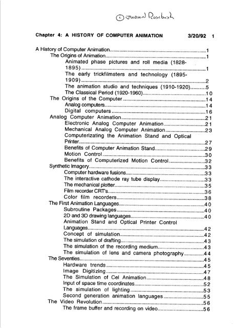
Chapter 4: A HISTORY OF COMPUTER ANIMATION ... - Vasulka.org
Chapter 4: A HISTORY OF COMPUTER ANIMATION ... - Vasulka.org
Chapter 4: A HISTORY OF COMPUTER ANIMATION ... - Vasulka.org

You also want an ePaper? Increase the reach of your titles
YUMPU automatically turns print PDFs into web optimized ePapers that Google loves.
tea:1 i20SZ bu :J1,<br />
<strong>Chapter</strong> 4 : A <strong>HISTORY</strong> <strong>OF</strong> <strong>COMPUTER</strong> <strong>ANIMATION</strong> 3/20/92 1<br />
A History of Computer Animation . . . . . . . . . . . . . . . . . . . . . . . . . . . . . . . . . . . . . . . . . . . . . . . . . . . . . . . . . . . . . . . . . . . . .1<br />
The Origins of Animation . . . . . . . . . . . . . . . . . . . . . . . . . . . . . . . . . . . . . . . . . . . . . . . . . . . . . . . . . . . . . . . . . . . . . . . . . .1<br />
Animated phase pictures and roll media (1828-<br />
1895) . . . . . . . . . . . . . . . . . . . . . . . . . . . . . . . . . . . . . . . . . . . . . . . . . . . . . . . . . . . . . . . . . . . . . . . . . . . . . . . . . . . . . . . . . . . . . . . . . . . . .1<br />
The early trickfilmsters and technology (1895-<br />
1909) . . . . . . . . . . . . . . . . . . . . . . . . . . . . . . . . . . . . . . . . . . . . . . . . . . . . . . . . . . . . . . . . . . . . . . . . . . . . . . . . . . . . . . . . . . . . . . . . . . . ..2<br />
The animation studio and techniques (1910-1920) . . . . . . . . . .5<br />
The Classical Period (1920-1960) . . . . . . . . . . . . . . . . . . . . . . . . . . . . . . . . . . . . . . . . . . . 1 0<br />
The Origins of the Computer . . . . . . . . . . . . . . . . . . . . . . . . . . . . . . . . . . . . . . . . . . . . . . . . . . . . . . . . . . . . . . . . . ..14<br />
Analog computers . . . . . . . . . . . . . . . . . . . . . . . . . . . . . . . . . . . . . . . . . . . . . . . . . . . . . . . . . . . . . . . . . . . . . . . . . . . ..14<br />
Digital computers . . . . . . . . . . . . . . . . . . . . . . . . . . . . . . . . . . . . . . . . . . . . . . . . . . . . . . . . . . . . . . . . . . . . . . . . . . ..16<br />
Analog Computer Animation . . . . . . . . . . . . . . . . . . . . . . . . . . . . . . . . . . . . . . . . . . . . . . . . . . . . . . . . . . . . . . . . . . ..21<br />
Electronic Analog Computer Animation . . . . . . . . . . . . . . . . . . . . . . . . . . . . . . . . .21<br />
Mechanical Analog Computer Animation . . . . . . . . . . . . . . . . . . . . . . . . . . . . . . . .23<br />
Computerizating the Animation Stand and Optical<br />
Printer. . . . . . . . . . . . . . . . . . . . . . . . . . . . . . . . . . . . . . . . . . . . . . . . . . . . . . . . . . . . . . . . . . . . . . . . . . . . . . . . . . . . . . . . . . . . . . . . . . .2 7<br />
Benefits of Computer Animation Stand . . . . . . . . . . . . . . . . . . . . . . . . . . . . . . . . . .2 9<br />
Motion Control . . . . . . . . . . . . . . . . . . . . . . . . . . . . . . . . . . . . . . . . . . . . . . . . . . . . . . . . . . . . . . . . . . . . . . . . . . . . . . . . . ..3 0<br />
Benefits of Computerized Motion Control . . . . . . . . . . . . . . . . . . . . . . . . . . . . .32<br />
Synthetic Imagery . . . . . . . . . . . . . . . . . . . . . . . . . . . . . . . . . . . . . . . . . . . . . . . . . . . . . . . . . . . . . . . . . . . . . . . . . . . . . . . . . . . . . . . .3 3<br />
Computer hardware fusions . . . . . . . . . . . . . . . . . . . . . . . . . . . . . . . . . . . . . . . . . . . . . . . . . . . . . . . ..3 3<br />
The interactive cathode ray tube display . . . . . . . . . . . . . . . . . . . . . . . . . . . . . .3 3<br />
The mechanical plotter . . . . . . . . . . . . . . . . . . . . . . . . . . . . . . . . . . . . . . . . . . . . . . . . . . . . . . . . . . . . . . . . . .3 5<br />
Film recorder CRT's . . . . . . . . . . . . . . . . . . . . . . . . . . . . . . . . . . . . . . . . . . . . . . . . . . . . . . . . . . . . . . . . . . . . . . . . .3 6<br />
Color film recorders . . . . . . . . . . . . . . . . . . . . . . . . . . . . . . . . . . . . . . . . . . . . . . . . . . . . . . . . . . . . . . . . . . . . . . .38<br />
The First Animation Languages . . . . . . . . . . . . . . . . . . . . . . . . . . . . . . . . . . . . . . . . . . . . . . . . . . . . . . . . . . . . . .4 0<br />
Subroutine Packages . . . . . . . . . . . . . . . . . . . . . . . . . . . . . . . . . . . . . . . . . . . . . . . . . . . . . . . . . . . . . . . . . . . . . . .4 0<br />
2D and 3D drawing languages . . . . . . . . . . . . . . . . . . . . . . . . . . . . . . . . . . . . . . . . . . . . . . . . . . . . . .40<br />
Animation Stand and Optical Printer Control<br />
Languages . . . . . . . . . . . . . . . . . . . . . . . . . . . . . . . . . . . . . . . . . . . . . . . . . . . . . . . . . . . . . . . . . . . . . . . . . . . . . . . . . . . . . . . . . . . . .4 2<br />
Concept of simulation . . . . . . . . . . . . . . . . . . . . . . . . . . . . . . . . . . . . . . . . . . . . . . . . . . . . . . . . . . . . . . . . . . . .42<br />
The simulation of drafting . . . . . . . . . . . . . . . . . . . . . . . . . . . . . . . . . . . . . . . . . . . . . . . . . . . . . . . . . . .43<br />
The simulation of the recording medium . . . . . . . . . . . . . . . . . . . . . . . . . . . . . . .4 3<br />
The simulation of lens and camera photography . . . . . . . . . . . . . . . .4 4<br />
The Seventies . . . . . . . . . . . . . . . . . . . . . . . . . . . . . . . . . . . . . . . . . . . . . . . . . . . . . . . . . . . . . . . . . . . . . . . . . . . . . . . . . . . . . . . . . . . . . . . ..4 5<br />
Hardware trends . . . . . . . . . . . . . . . . . . . . . . . . . . . . . . . . . . . . . . . . . . . . . . . . . . . . . . . . . . . . . . . . . . . . . . . . . . . . . ..4 5<br />
Image Digitizing . . . . . . . . . . . . . . . . . . . . . . . . . . . . . . . . . . . . . . . . . . . . . . . . . . . . . . . . . . . . . . . . . . . . . . . . . . . . . .47<br />
The Simulation of Cel Animation . . . . . . . . . . . . . . . . . . . . . . . . . . . . . . . . . . . . . . . . . . . . . .48<br />
Input of space time coordinates . . . . . . . . . . . . . . . . . . . . . . . . . . . . . . . . . . . . . . . . . . . . . . . .52<br />
The simulation of lighting . . . . . . . . . . . . . . . . . . . . . . . . . . . . . . . . . . . . . . . . . . . 5 3<br />
Second generation animation languages . . . . . . . . . . . . . . . . . . . . . . . . . . . . . . ..5 5<br />
The Video Revolution . . . . . . . . . . . . . . . . . . . . . . . . . . . . . . . . . . . . . . . . . . . . . . . . . . . . . . . . . . . . . . . . . . . . . . . . . . . . . . . . ..5 6<br />
The frame buffer and recording on video . . . . . . . . . . . . . . . . . . . . . . . . . . . . . . .5 6
<strong>Chapter</strong> 4: A <strong>HISTORY</strong> <strong>OF</strong> <strong>COMPUTER</strong> <strong>ANIMATION</strong> 3/20/92 2<br />
Video image digitizing . . . . . . . . . . . . . . . . . . . . . . . . . . . . . . . . . . . . . . . . . . . . . . . . . . . . . . . . . . . . . . . . . . .5 8<br />
Digital Video Effects . . . . . . . . . . . . . . . . . . . . . . . . . . . . . . . . . . . . . . . . . . . . . . . . . . . . . . . . . . . . . . . . . . . . . .5 8<br />
Turnkey animation systems . . . . . . . . . . . . . . . . . . . . . . . . . . . . . . . . . . . . . . . . . . . . . . . . . . . . . . . . .6 0<br />
Motion Control Languages and Interactive Systems . . . . . . . . . 61<br />
PC Animation Systems. . . . . . . . . . . . . . . . . . . . . . . . . . . . . . . . . . . . . . . . . . . . . . . . . . . . . . . . . . . . . . . . . . .6 3<br />
Current Issues including Kinematics, Dynamics, Graftals,<br />
Flocking . . . . . . . . . . . . . . . . . . . . . . . . . . . . . . . . . . . . . . . . . . . . . . . . . . . . . . . . . . . . . . . . . . . . . . . . . . . . . . . . . . . . . . . . . . . . . . . . . . . . . . . . . . . .63<br />
The simulation of applications and scientific<br />
visualization . . . . . . . . . . . . . . . . . . . . . . . . . . . . . . . . . . . . . . . . . . . . . . . . . . . . . . . . . . . . . . . . . . . . . . . . . . . . . . . . . . . . . . . . . . . . . . . . ..64
<strong>Chapter</strong> 4 : A <strong>HISTORY</strong> <strong>OF</strong> <strong>COMPUTER</strong> <strong>ANIMATION</strong> 3/20/92 1<br />
A History of Computer Animation<br />
Computer animation emerged as a viable technology during the<br />
early 1960's as the still evolving digital computer was coupled with<br />
increasingly sophisticated graphical output devices .<br />
Depending upon what you decide is animation and what you<br />
decide constitutes a computer, it is easly to conclude that all<br />
animation is "computer" animation . The reason is because even<br />
classical (pre-computer) animation involves an animation languagea<br />
notational system which describe events or images over time . In a<br />
classical system, the instructions and graphical data are composed<br />
on paper, and the hardware execution is accompanied by an animation<br />
camera and camer operator-sort of a hardware/bioware<br />
combination . In a contemporary system the instructions and<br />
graphical data are composed on magnetic media, and hardware<br />
execution is accompanished. by a computer automatically .<br />
If we restrict ourselves to the post-classical phase of the<br />
medium, the first computer animations emerge in the early 1960s,<br />
depending on what you mean by a computer and by animation . The<br />
fundamentals to achieve this and milestones are detailed in sections<br />
on motion control, CRT and raster graphics, hardware and media<br />
approaches, and increasingly sophisticated software simulations of<br />
line drawing, drafting, imaging, perspective, color, opacity, lighting,<br />
and textures .<br />
Finally we review how time, the subject of our first chapter,<br />
emerged as a varible, and take a careful look at the key features of<br />
animation language, both before the computer as well as how they<br />
have evolved in processes like motion control, 3D lens and camera<br />
simulation, communications between temporal events, and editing<br />
(fig . 1) .<br />
The Origins of Animation<br />
Animated phase pictures and roll media (1828-1895)<br />
Animation predates the motion pictures and was a popular<br />
entertainment during the 19th century and sold by the thousands to<br />
the households of the industrial age . These animated phase<br />
pictures-short cycles of animation-were marketed on both disk and<br />
cylinder machines . The disk machines, such as the<br />
phenakistiscope (1828), arranged the series of discrete images<br />
1 . Control pannel shows themes leading to the discovery of<br />
computer animation . [Jud's Hypercard art] .
<strong>Chapter</strong> 4 : A <strong>HISTORY</strong> <strong>OF</strong> <strong>COMPUTER</strong> <strong>ANIMATION</strong> 3/20/92 2<br />
radically (fig . 31) . The cylinder machines, like the zoetrope (1832)<br />
mounted a paper band of images on the inside of a drum . The media<br />
was then spun and viewed through slots in media .<br />
Parisian Emile Reynaud opened the first movie theater, Theater<br />
Optique ., and began projecting animated movies created by drawing<br />
individual frames on rolls of paper (1892) . His roll media expanded<br />
animation sequences from short, second-long cycles to longer<br />
scenes, and his projector changed the audience from one viewer (or<br />
at best, a few) into an audience of hundreds, recreating the<br />
proscenium [sp] stage .<br />
Photographic roll film media began to be manufactured in 1888<br />
by Ge<strong>org</strong>e Eastman, the founder of Eastman Kodak Company . Just<br />
before the turn of the century Thomas Edison in New Jersey (1889),<br />
and the Lumiere brothers in Paris (1895) successfully fused<br />
photography with the moving picture, solving both the recording and<br />
projection problems .<br />
Thus as the phase cycles of disc, cylinder and paddlewheel<br />
media gave way to longer format roll media, and as the singleviewer<br />
peep show gave way to the projector and the multi-viewer<br />
movie theater, two media variables changed radically : The axis of<br />
time increased dramatically in magnitude, and the medium changed<br />
from individualistic to audience oriented . The integration of a<br />
moving picture photography and projection system catalyzed the<br />
process and purpose of animation, and during the next two decades<br />
many of the basic concepts of the medium were developed and<br />
deployed .<br />
The early trickfilmsters and technology (1895-1909)<br />
The first generation of the celluloid cinematographers<br />
included documentarians makeing observational films,<br />
trickfilmsters like magician Ge<strong>org</strong>es Melies, lightning cartoonists<br />
like J . Stewart Blackton, and newspaper cartoonists, like Emile Cohl .<br />
The first films, like Fred Ott's Sneeze (1894) depicted short single<br />
action scenes, but by 1896 the Lumieres had dispatched crews<br />
around the world to make "observational films" and before the turn<br />
of the century the camera was panning and being mounted on<br />
vehicles and boats . In 1903 cinematography was married to the<br />
story, as Edwin S . Porter introduced cross cuts and parallel action<br />
into The Great Train Robbery .<br />
It is convenient to identify three technical paths of motion<br />
picture development . The first is live action, which records real<br />
people and places, or actors on sets, using a (moveable) camera that<br />
records in real time . The second is animation, which employs
<strong>Chapter</strong> 4 : A <strong>HISTORY</strong> <strong>OF</strong> <strong>COMPUTER</strong> <strong>ANIMATION</strong> 3/20/92 3<br />
discrete drawings or adjustable physical 3D models, and a static,<br />
single frame (stop motion) camera . Animation is not recorded in<br />
real time . The third is trick film, which combines both of these<br />
techniques along with a host of processes indigenous to the medium<br />
itself . The trick film especially uses cinematic vehicles (aka<br />
special effects) to create an illusion .<br />
Edison's first trick film, probably directed by William Dickson,<br />
dramatized The Execution of Mary Queen of Scots (1895), and was a<br />
box office sensation (fig . 2) . The seemingly completely realistic<br />
beheading was accomplised using a technique called the arret, a<br />
technique that involves stopping the camera, moving actors, props,<br />
or artwork, and restarting the camera .<br />
The arret was used by all the early trickfilmseters including<br />
Blackton (1898), Booth (1906), and Chomon (1905), but nobody<br />
explored the physics of the new media better than Parisian Ge<strong>org</strong>e<br />
Melies, a vaudeville magician who built a camera/projector and<br />
began making and exhibiting trickfilms . In his shorts, Melies<br />
incorporated not only elaborate drawings and moving props into the<br />
set, but also a plethora of camera tricks . Legend has it the arret<br />
was "revealed" to Melies when he screened a reel that had been<br />
stopped and then restarted on a street with moving traffic .<br />
The arret is not quite animation, but a series of arrets, or<br />
single frame (aka stop motion) photography, become the basis of<br />
making animation, regardless of whether you are shooting 2D<br />
drawings or 3D objects . Just to what extent which of the pioneers<br />
used single frame photography is uncertain, because some of the pre<br />
1900 model photography was accomplised using invisible wires and<br />
was shot live action . But in 1907 two films by J . Stuart Blackton<br />
firmly established animation-one with blackboard drawing and the<br />
other with models . Once the gene is out of the box single framing is<br />
widely employed, and instigates the traditions of animation using<br />
clay, 2D silhouettes and cutouts, and 3D model animation .<br />
Another early development was single frame photography of<br />
the progressive development of a single drawing, usually today<br />
called a scratchon . The scratchon was evolved by lightning sketch<br />
vaudville artists like Blackton, who drew stores in real time, but<br />
couldn't resist stopping the camera and single framing while they<br />
2 . The arret is the technique of stopping the live action camera,<br />
manipulating the set, and running the camera again . Typically, as in<br />
the Edison Studio's Execution of Mary Queen of Scots, the camera is<br />
locked off and immobil . [Locate]
<strong>Chapter</strong> 4: A <strong>HISTORY</strong> <strong>OF</strong> <strong>COMPUTER</strong> <strong>ANIMATION</strong> 3/20/92 4<br />
advanced their chalk-on-a-blackboard drawings, as in Humorous<br />
Phases of Funny Face (1907) (fig . 6) .<br />
The technique of single frame recording individual and<br />
successive ink-on-paper drawings (fig . 8) was pioneered by two<br />
newspaper cartoonists who f<strong>org</strong>ed a relationship between the daily<br />
newspaper and the cinema : Emile Cohl in France (1908) and Windsor<br />
McCay in New York (1911) . The longer running times of roll media<br />
removed the constraint of drawing only cycles ; action could<br />
commence and continue without returning to its origin . Thus<br />
animation evolved from the concept of a phase picture to the concept<br />
of a shot, a contiguous piece of action .<br />
Another special effect was the multiple exposure, pioneered<br />
by Melies (1902) and others, which involved exposing, rewinding, and<br />
then reexposing a single strand of film emulsion . The multiple<br />
exposures could superimpose images, create dissolves, and let<br />
Melies act with himself on the screen . Edwin Porter combined<br />
multiple exposures with mattes to capture a moving exterior<br />
outside the window of the station house in The Great Train Robbery<br />
(1903) . Worked with a twist, multiple exposures may also be used<br />
to combine animation with live action, as in Edison's Enchanted<br />
Drawing (1900), which incorporated blackboard chalk scratchons and<br />
an actor (fig . 11), possibly shot with a split screen technique .<br />
Remember that in these days before optical printers or video<br />
compositers the entire image had to be exposed into one original<br />
camera negative . Reverse action, action that is running<br />
backwards, was discovered in 1903 .<br />
But it is worth observing that the purpose of the special effect<br />
was viewed quite differently by early directors : For Melies the<br />
6 . Scratchon . Single frame photography of progressive<br />
blackboard scratchon drawing is technique used to make J . Stuart<br />
Blackton's Humorous Phases of Funny Face in 1907 . [locate and<br />
permission]<br />
8 . Single frame photography of successive paper drawings breaks<br />
away from cyclic phase drawing and is a pathway to the cel system .<br />
In Windsor McCay's Gertie the Trained Dinosaur the entire drawing is<br />
recreated for each frame .<br />
11 . Split reel technique was probably used in this 1900 short<br />
produced by the Edison Company called The Enchanted Drawing . In<br />
the action an artist sketches the face of a sad tramp on a paper pad .<br />
Next he draws a cigar and the tramp begins to puff large clouds of<br />
smoke as the actor leaps back in astonishment . [locate and<br />
permission eg in Madsen]
<strong>Chapter</strong> 4 : A <strong>HISTORY</strong> <strong>OF</strong> <strong>COMPUTER</strong> <strong>ANIMATION</strong> 3/20/92 5<br />
magician it was a vehicle to perform magic, for Porter the<br />
storyteller it was a vehicle to advance the photoplay, a story told<br />
cinematically and incorporating temporal devices, especially cuts<br />
which change the point of view, frame close ups, reveal different<br />
players' perspectives, and cross cut between parallel temporal<br />
action .<br />
Thus by the early 1910s the stage was set-technologicaly<br />
(cinema plus processes), dramatically (in the sense of the<br />
photoplay), and sociologically (in the sense of the vaudville theatre<br />
and audience)-for a cinema industry to evolve . And the special<br />
effects and single frame animation studio were now established as<br />
part of the film genre within it .<br />
The animation studio and techniques (1910-1920)<br />
During the first half of the 20th century, animation reached<br />
maturity . The technique of drawing on paper and photographing the<br />
successive individual frames, pioneered independently by Emile Cohl<br />
and Windsor McCay, soon evolved into a cartoon animation style<br />
quite independent of the trick film or live action .<br />
Cohl, among other inovations, delighted audiences with the use<br />
of the metamorphosis, a shape transformation in which an<br />
animated outline magically transitioned from one object to another<br />
(fig . 13) . Often the two extreme shapes have quite different<br />
meanings, and the effect is an alternative to a cut or dissolve .<br />
Meanwhile, McCay migrated his Little Nemo character from<br />
newsprint to the screen (1911) ; and with it came conventions of the<br />
newspaper cartoon, such as expression bubbles atop characters-a<br />
textbook example of McLuhan's adage of a new medium mimicking an<br />
established one . Next McCay brought Gertie the Trained Dinosaur<br />
(1914) to life, the first of a long linage of cartoon animals (again,<br />
fig . 8) . McCay has said that at first audiences were unaware of the<br />
technology and suspected tricks with wires, and that it was not<br />
untill he animated a dinosaur-truely a profound creature fresh on<br />
the heels of Darwin-that they understood that it was the drawing<br />
13 . Metamorphis is the changing of one shape into another . In<br />
computer animation it may be a trivial as inbetweening a polygon in<br />
the shape of a keyhole to a polygon the shape of a circle, or as<br />
complicated as a fully rendered Buick melting and becomming a river<br />
of fire . It is one effect where the computer vastly expands the<br />
classical reportroire . The illustration depicts a problem slightly<br />
more complicated than trivial because it incorporates lines in<br />
addition to the outline . (Drawing by Dick Rauh and Suk-11 Hong .)
<strong>Chapter</strong> 4 : A <strong>HISTORY</strong> <strong>OF</strong> <strong>COMPUTER</strong> <strong>ANIMATION</strong> 3/20/92 6<br />
that was being made to change . The vadlidity of the anecdote is<br />
suspect when one remembers that the public already had been<br />
watching animated phase pictures for almost a century ; what was<br />
novel was the incorporation of the photographic process into<br />
animation .<br />
By the early teens, people began to test the idea the animation<br />
might make a business-that is that sufficent serindipity existed<br />
between the emerging audience and the animator that it was<br />
practical to construct a plant capable of mass media fabrication .<br />
After all, at 1440 paper drawings per minute, cartoons doen't get<br />
finished too often if one person is doing all the drawings .<br />
The first animation studios where founded independently in the<br />
early teens by Americans John Bray and Earl Hurd, and by Canadian<br />
Raoul Barre . The first technological advances sought to refine the<br />
production process and make it quicker, less labor intensive, and<br />
more accurate . This entailed the implementation of a few basic<br />
procedures that remain with us today as tools of the trade . These<br />
include systems for registration, the cell process, the perfection of<br />
the animation camera, and rotoscopy . The resulting animation studio<br />
mimiced Western fasination with the assembly line and mass<br />
production ; even in the early 1990s it remains a financially viable<br />
model . Teamwork, specialization, precision, and information flow<br />
constitute a few of its salient features .<br />
Frame to frame registration is important in animation and the<br />
solution is simply rigor : register everything-the drawings, the<br />
camera, and the film . The first registration systems for drawings<br />
used optical crosshairs or bullseyes drawn on the paper, but this<br />
approach was soon superseeded by a mechanical pegbar registration<br />
system credited to Barre (1914), in which pegs in the drawing table<br />
and holes in the drawing paper keep all the drawings in allignment .<br />
The drawing paper, then as now, is slightly transparent to faciliate<br />
tracing . The system is not perfect-holes wear and ten to lose<br />
allignment with repeated repegging, but basically the system works<br />
(fig . 15) .<br />
15 . Optical registration systems for artwork include bullseyes aka<br />
crosshairs (a) ; mechanical systems include pegbar (b) . In the early<br />
days each studio made its own pegbar, but by the late 1940s three<br />
American standards emerged--the Acme, Signal Corps, and Oxberry,<br />
illustrated here . Note that the paper and peg dimensions are slightly<br />
different ; the hole is narrower (to give the paper a good grip) and<br />
slightly wider (to let air pass during pegging) . In practice the pegs
<strong>Chapter</strong> 4 : A <strong>HISTORY</strong> <strong>OF</strong> <strong>COMPUTER</strong> <strong>ANIMATION</strong> 3/20/92 7<br />
The registration of the recording medium-35mm film-is more<br />
difficult ; remember that the area of a frame of film is is about 70<br />
times smaller than the area of a 12 field cel . The solution requires<br />
standardization with strict tolerances so that the perf holes (fig .<br />
14) in the film match exactly to mechanical registration pins in<br />
the camera shuttle (1912) . This made the photographed image more<br />
steady, elimated weave, and paved the way for more sophsiticated<br />
special effects involving multiple exposures, since repeated<br />
exposures of one piece of film or composite exposures from many<br />
pieces of film would all be alligned . Registration would not become<br />
an animation issue again until the era of videotape .<br />
One benefit of registration in the drawing process is to enable<br />
individual drawings to be decomposed into static and moving parts<br />
which are handled separately . A simple way to do this is to employ<br />
cutouts, paper drawings laid overtop a background and<br />
incrementally moved and photographed (fig . 15.5) . The system is<br />
also have curved tops, as you can see in the schematic (c) . (Drawing<br />
by Dick Rauh and Suk-11 Hong .)<br />
14 . Perforation holes are found in many kinds of roll media<br />
including paper tape and movie film . In 35mm film there are two<br />
major types : the Bell and Howell pert used in negative and<br />
intermediate stocks, and the Kodak Standard pert used in prints that<br />
are projected . The difference is that the B&H pert is designed to<br />
hold registration whereas the Kodak Standard is optimized for<br />
repeated projection at higher speed . Stock is also manufactured in<br />
two different pitches, that is the distance from one perfhole to the<br />
next . The shorter pictch ( .1866") is found in negative stocks, the<br />
longer pitch is used for release prints, and is an artifact of how<br />
printing machines are threaded . In 16mm film (not shown here)<br />
there is only one kind of perfhole . (Illustration by Suk-11 Hong .)<br />
15 .5 Cuttouts aka the decoupage system . The moving part of the<br />
image (a) is cut out of the whole sheet along the dotted line and laid<br />
overtop a static background (b) and photographed (c) . Nature<br />
performs hidden surface removal . Only that part of the image which<br />
moves is redrawn and cut out for each frame . Cutouts are not<br />
necessarly attached to pegbar, but if they are free floating they do<br />
need some kind of movement guide . Some historians also call what<br />
is shown in this drawing the slash system and if you compare it to<br />
figure 16 you will observe its only difference is that here the<br />
moving action is physically in front of the static . (Drawing by Dick<br />
Rauh ; the reader is cautioned that his selection of Bette Boop to
<strong>Chapter</strong> 4: A <strong>HISTORY</strong> <strong>OF</strong> <strong>COMPUTER</strong> <strong>ANIMATION</strong> 3/20/92 8<br />
more efficient because the whole image is not redrawn each frame ;<br />
furthermore the image is more steady . In practice the cuttout need<br />
not be a free floating object, and may be attached to peg holes . It<br />
may also be articulated, a technique pioneered by Cohl and<br />
Armstrong (1910) . In Europe the cutout system remained the<br />
preferred method of production as late as the 1930s .<br />
Another strategy emerged at the Barre studio called the slash<br />
system, in which scenes were printed in mass on transcluent paper<br />
(1914) . The part of the field that contained changing action was<br />
"slashed out" with a rasor blade and the paper laid overtop a clean<br />
sheet, onto which the changing action was drawn . The pair of<br />
drawings was then shot together (fig . 16) .<br />
But more important still was the perfection by Earl Hurd of the<br />
cel process (1915) (fig . 17) . The cutout and the slash system<br />
reduced work because the entire scene was not redrawn every frame ;<br />
furthermore the line quality is more stable, since the unchanging<br />
lines were the same on each printed sheet . The cel system expands<br />
this concept by inking the drawing onto a registered transparent cel,<br />
opaquing it by painting the backside of the cel, and then layering this<br />
cel overtop of a single static background and photographing the<br />
stack . The cel process separates foreground and background art into<br />
work which gets drawn once and work which gets drawn every<br />
frame, and it allows the foreground cel to be translated relative to<br />
the background . This requires the invention of a compound table<br />
onto which the backgrounds and cels are placed for photography and<br />
illustrate this technology may be placing her into a technology<br />
which is before her time .)<br />
16 . The slash system (aka the slash and tear system) begins with<br />
identical drawings that have been printed onto paper and pegged .<br />
Whever action occurs the drawing is torn away (leaving a hole in the<br />
paper), laid over top a clean sheet of paper, and the area inside the<br />
hole is drawn in . This approach is the opposite of the cutout because<br />
the static action is laid on top of the changing element, rather than<br />
laying the changing element on top of the background . This setup is<br />
useful when the changing element wants to go behind things .<br />
17 . The cel system . The background is drawn onto paper and<br />
painted ; the foreground is drawn onto paper, then trace inked onto<br />
one or more flexible transparent cels, backside painted with opaque<br />
colors, then laid overtop the background and photographed . Action<br />
which is static is draw onto cels or backgrounds which are used for<br />
many frames, only the moving parts are transferred to cels which<br />
are different for each frame . [color example, plus process diagram] .
<strong>Chapter</strong> 4 : A <strong>HISTORY</strong> <strong>OF</strong> <strong>COMPUTER</strong> <strong>ANIMATION</strong> 3/20/92 9<br />
moved on calibrated scales . It was also possible to move the camera<br />
closer or farther away from the table . These new variables were<br />
tools of the new animation directors .<br />
The facility of the animation stand to also project images<br />
provided a way to convert live action images back into drawings, a<br />
process called rotoscopy, and attributed to director Max Fleischer<br />
(1915) in the midst of trying to figure out how to dramatically<br />
increase throughput : simply film actors and 3D objects using live<br />
action, and then project the frames one by one, trace 2D outlines of<br />
the characters or objects onto individual drawings, and send the<br />
drawings down the animation process pipeline . Rotoscopy remains a<br />
basic tool today in film and video post-production, especially in<br />
situations where mattes cannot be generated automatically from the<br />
footage . Rotoscopy is employed whenever animated characters need<br />
to realistically interact with live action, as in Who Framed Roger<br />
Rabbit, and in creating effects like the light swords in Star Wars<br />
(fig . 23) . It is also used to guage the positions of puppets during<br />
stop-motion photography, a technique developed by Ge<strong>org</strong>e Pal in<br />
1933 .<br />
In addition to the animation camera stand one final piece of<br />
filmmaking technology emerged during the teens, completing the<br />
basic technology . This was a special effect called the traveling<br />
matte shot, invented by American Frank Williams (1918) . The new<br />
trick was accomplished by filming an actor against an all white or<br />
black background and then preparing a high contrast matte from this<br />
negative which was used to combine, or "matte in" the actor to a<br />
new background scene . At first the trick was done entirely with a<br />
camera, but in the 1930s was streamlined on the optical printer .<br />
After the 1950's the process was worked in color, as well as being<br />
adopted to video, first in black and white and then color .<br />
In Europe a wider variety of techniques were explored,<br />
especially the use of 2D and 3D articulated puppets, designed to<br />
be moved incrementally and photographed on a frame by frame basis<br />
23 . Rotoscopy . The 2D rotoscoped outline of a live action watch<br />
permits the computer animator to visualize where this 3D object<br />
will exist in the synthetic landscape . The final computer graphic<br />
production will consist of the animated wire frame background<br />
minus the tracing, plus a black and clear core matte of the traced<br />
watch . These mattes will then be used to combine the CG<br />
background with the live action foreground . (Courtesy of Digital<br />
Effects .)
<strong>Chapter</strong> 4 : A <strong>HISTORY</strong> <strong>OF</strong> <strong>COMPUTER</strong> <strong>ANIMATION</strong> 3/20/92 10<br />
in miniture 3D sets (fig . 23.2) . The first puppet animated films,<br />
such as Ladislas Starewicz's mechanical insects (1911) and Edward<br />
Roger's War in Toyland (1912), introduced a host of inovations . The<br />
basic issue of figure movement is solved with an internal<br />
armature, a metal skeletal structure with articulated joints that<br />
can be moved into various positions, and around which wooden (or in<br />
later years rubber or plastic) characters are built . Techniques to<br />
change facial expressions including the use of flexiable facial<br />
masks by Starewicz (fig 23 .5), and the idea of multiple heads for<br />
a finite set of facial expressions-Starewicz is said to have as many<br />
as 200 different heads for major characters (fig . 24) . Three<br />
dimensional computer animation is often simply virtual puppet<br />
animation .<br />
By and large the content of this early fare was the cartoon<br />
character, already well stablized in the newspaper . It is not<br />
surprising therefore that the early evolution of this character was<br />
initially dominated by newspapermen . The trickfilm and lightning<br />
cartoonists no longer provided leadership, perhaps because the<br />
comic strip artists brought with them not only the characters but<br />
also the narrative . In fact, the cartoon influences date from before<br />
the arrival of the cartoonists ; as early as 1906 Porter had adapted<br />
Winsor McCay's Dreams of a Rarebit Fiend . In New York, Bray's<br />
studio motive was a series of Colonel Heeza Liar shorts (1913) ; San<br />
Francisco cartoonist Bud Fisher's Mutt and Jeff was adapted to the<br />
screen (1913), and in New York Max Fleischer introduced Ko-Ko the<br />
Clown (1914) . Finally, at the end of the decade, Pat Sullivan and<br />
Otto Messner created Felix the Cat (1919), a character developed<br />
23 .2 Puppet animation . The tradition of animating 3D objects is as<br />
old as animating 2D drawings and a major archology of computer<br />
animation . Classical puppets often include articulated skeletons,<br />
hinged jaws for lip syncing, and facial features which are subjected<br />
to variance .<br />
23 .5 Facial masks are an early puppet concept easily adapted to<br />
computer animation . These vector graphic templates were made by<br />
painting lines on an actor's face, and shooting still coplaner<br />
photographs of the actor making different expressions . These are<br />
then digitized . Because the number of quadralaterials in each mask<br />
is the same, the masks may be computationally interpolated or<br />
blended to animate from one expression to another . (Courtesy Pierre<br />
LaChapel and Philippe Bergerson .)<br />
24 . Catagorical sets of body parts, such as replaceable heads and<br />
hands, facilitate the work of the puppet animator .
<strong>Chapter</strong> 4 : A <strong>HISTORY</strong> <strong>OF</strong> <strong>COMPUTER</strong> <strong>ANIMATION</strong> 3/20/92 1 1<br />
especially for the screen and the industry's first cartoon superhero .<br />
Felix the megastar paved the way for a succession of cartoon<br />
animals .<br />
The Classical Period (1920-1960)<br />
The most widely known proponent of the cartoon process was a<br />
man born after the invention of the cinema, Walt Disney . Disney<br />
started out in Kansas City, but by the 1920s he had moved to<br />
Hollywood and in a few short years technologically and artistically<br />
leapfroged the business . Disney encouraged the process of animating<br />
by extremes, whereby the animator drew only the key positions,<br />
and the intermediate drawings between the poses were drawn by an<br />
assistant, called the inbetweener. The number of inbetweens as<br />
well as their temporal relation to the two keys was indicated on a<br />
timing diagram, also prepared by the animator, that accompanied<br />
the key drawings (fig . 8 .5) . Standarization also involved utilization<br />
of model sheets, coloring diagrams, and exposure or dope<br />
sheets, which dictated to the cameraman what cels were to be<br />
placed over what backgrounds on what frames . Dope sheet<br />
formalized the relationship between animator and cameraman, and<br />
centralized production from an upstream control point . Disney<br />
introduced the storyman, who wrote the scripts and storyboarded<br />
the action, and incorporated the pencil test as routine procedure .<br />
The preeminent achievements of the studio begin to get realized in<br />
1928, when the synchronized sound cartoon Steamboat Willie<br />
launched the career of Mickey Mouse .<br />
8 .5 . Key frames, inbetween and timing diagram . The idea of<br />
animating from pose to pose, as opposed to "straight ahead"<br />
animation where the animation has no clearly defined extreme<br />
positions, has wide ranging effects in animation . In classical<br />
cartoon animation it invited specialization of labor, with less<br />
skilled labor drawing the inbetweens--the frames in between the<br />
extremes . In 3D computer animation the process is the same : the<br />
extremes are defined parametrically (eg joint angles), and the<br />
computer calculates the inbetweens . In classical animation the<br />
temporal relationships of the inbetweens to the keys is specified by<br />
a hand drawn timing diagram ; in computer animation this is usually<br />
done by calculating the ease kinematically . The computational<br />
analogy of the straight ahead style is dynamic modeling ; details of<br />
dynamic and kinematic calculations are detailed in a separate<br />
chapter .
<strong>Chapter</strong> 4 : A <strong>HISTORY</strong> <strong>OF</strong> <strong>COMPUTER</strong> <strong>ANIMATION</strong> 3/20/92 1 2<br />
The 1930's also saw technological advances in the overall film<br />
process that were adopted by Disney : color (1932) . and the cartoon<br />
feature (1937), stereo sound (1940), and automation of the inking<br />
step with xerography (1961) . In the end Disney actually built his 3D<br />
synthetic environments (the theme parks), and successfully<br />
exploited the emerging television business .<br />
Advances in the animation camera stand and optical printer<br />
were also made during the 1930's . Early animation stands were<br />
homebuilt affairs-Disney used pipe in some of his rigs-and only<br />
over time did the features fully evolve . Initially the stands were<br />
operated manually with control wheels calibrated in real world<br />
inches . The complement of features beyond pan, tilt, zoom, and<br />
traveling pegbar came to include the rotating table and the<br />
pantograph, a mechanical arm which allowed the cameraman to<br />
follow a motion pathway, an XY graph that showed both the<br />
position and timing of the artwork (fig . 96) . Disney built his famous<br />
multiplane camera with multiple platins, spaced several inches<br />
apart so as to entice the three dimensional feel (1937) .<br />
Like the animation stand the first optical printers, like the<br />
Acme 103 designed by Linwood Dunn, were completely mechanical .<br />
An optical printer is much like an animation stand, only instead of<br />
photographing artwork it photographs film (fig . 3 .3) . The<br />
development of optical printers in the early 1930s vastly expanded<br />
the realm of special effects . First of all, the optical printer<br />
increased the precision of matte work, and moved a host of incamera<br />
effects-including the arret, multiple exposure and<br />
superimposition, reverse action, fade, and dissolve-from the set to<br />
post production . All may be invoked as an afterthought to principle<br />
photography, and with much more precision . But more importantly,<br />
the optical printer created entirely new effects possibliities,<br />
allowing images to be repositioned, enlarged or reduced, or freeze<br />
framed .<br />
In the 1950s a machinest named John Oxberry motorized and to<br />
some extent automated both the stand and the optical printer . On<br />
the stand he implemented a follow focus system so that the focal<br />
length of the lens was mechanically computed and set as the camera<br />
moved closer and further away from the artwork . Manually operated<br />
3 .3 Optical printer . The photographic axis is usually horizontal<br />
and the field of view is a film frame. The camera, projector, and<br />
aerial heads can each translate in XYZ and may rotate . The aerial<br />
image projector is optional and is used when it is necessary to carry<br />
a matte roll . (Courtesy Focal Press .)
<strong>Chapter</strong> 4 : A <strong>HISTORY</strong> <strong>OF</strong> <strong>COMPUTER</strong> <strong>ANIMATION</strong> 3/20/92 1 3<br />
control wheels were replaced or suplemented with electric motors<br />
which were operated from a control pannel . Digital readouts were<br />
standarized for all the axes of variance-including a frame counter,<br />
the compound positions, and zoom . This instrumentation may be<br />
designed to be calibrated in either real inches or virtual ones . (The<br />
accuracy of a stand is about .001") . The shutter was also<br />
numerically calibrated to faciliated in-camera dissolves and fades .<br />
In a mechanical sense Oxberry's dual columns minimized the<br />
spurious movements of the camera which contributed to jerking<br />
images . Oxberry's motorized optical printer included a second<br />
playback shuttle ; this allowed mattes to be placed in front of the<br />
lens instead of bipacked adjacent to the recording emulsion . Thus<br />
when the computer got invented the automation the stand and printer<br />
could be easily developed further .<br />
But the thirties cartoon style, with its hard, inked outline and<br />
solid color area was not a Disney exclusive . Walter Lantz, Warner<br />
Brothers, and MGM all formed studios, and a farm full of cartoon<br />
characters was born . This tradition of chase sequences and sight<br />
gags is so pervasive that most Americans don't even know that<br />
whole other traditions of animation exist .<br />
One form of these is an articulated cuttout, often called a<br />
marionette, but which in contemporary terms we would call a 2 D<br />
skeletal animation system . In physical terms these articulated<br />
cutout consisted of shapes (such as the body of a figure) connected<br />
together with rotating joints, and were often made of opaque sheet<br />
metal and used in silhouette backlit, a technique influenced by<br />
shadow theater . Variations in the real world include the use of<br />
stained glass, which add color, as well as painted color and toplight .<br />
One of the first to popularize this approach was the German Lotte<br />
Reiniger, whose signature included rotating the jointed 2D linkages<br />
to perform magical metamorphosizations, like two birds becomming<br />
a dancing girl in her feature film The Adventures of Prince Achmed<br />
(1926) .<br />
The German school also evolved a style of pure abstract<br />
animation, which even in the pre-sound days was designed to be<br />
synchronized to live music . One of these first music visualization<br />
films was Walter Ruttman's Lightplay Opus I (1921), other pioneers<br />
included Hans Richter, Oskar Fischinger, Fernand Leger, Marcel<br />
Duchamp, Paszlo Moholy-Nagy, the Sweed Viking Eggeling, and the<br />
New Zealander Len Lye. Like their cartoon counterparts, the abstract<br />
filmmakers, particularly Fischinger, migrated to color and soundon-film<br />
during the 1930s . Much of this work is very procedural in
<strong>Chapter</strong> 4 : A <strong>HISTORY</strong> <strong>OF</strong> <strong>COMPUTER</strong> <strong>ANIMATION</strong> 3/20/92 1 4<br />
design (fig . 26) . In America the abstract movement was formalized<br />
further by John and James Whitney, who employed mechanical<br />
pantographs to control paper cutouts (1944), very much in the<br />
linkages tradition of Reiniger . And abstraction will continue to be a<br />
theme of the motion graphics school . We develop both of these<br />
themes in the sections on Analogue Computer Animation and Motion<br />
Graphics/Motion Control .<br />
Eastern European countries lead developments in puppet<br />
animation ; major works include a feature film by the Russian<br />
Aleksander Ptu hko called The New Gulliver (1934) and a phethoria<br />
of work bN_ckoslovak Jiri Trnka and others since 1949 .<br />
e 1930s and 1940s are also a period of experimentation<br />
with still other techniques, including directly drawing on film,<br />
the use of sand on glass, the sliced wax block, and the pinscreen<br />
(1934), a gridlike screen of sliding pins which forms (for all<br />
practical purposes) a physical pixel memory . The pinscreen is lit<br />
from the side so as to cast shadows, and thus luminence is<br />
analogical to the physical height of the pin, and thus the length of<br />
its shadow . Animated pixel graphics thus also anticipated the<br />
computer .<br />
This leaves us at the advent of the computer .<br />
The Origins of the Computer<br />
Analog computers<br />
Computers date from antiquity and they take many forms .<br />
What they share in common is that they employ a methodology to<br />
solve problems : extract answers from data and to make preductions .<br />
Analogue computers are devices for solving problems that<br />
utilize physical quantities capable of continuous change . The<br />
physical displacement measures might be distance, rotation, weight,<br />
voltages (Wheatstone's bridge is an electrical analog computer), or<br />
areas . We are so used to thinking in numbers today that we must<br />
remember that analog computers can calculate entirely without<br />
numbers by using physical analogs such as eletricity or graphics .<br />
Analogue graphical computing devices include the right angle, plumb<br />
line, the balance, the compass (all antiquity), the plane table (4913C,<br />
modernized after 1620), proportional dividers, parallel rulers, the<br />
26 . Abstract geometric animation . Pioneered in Europe, these<br />
frames by Oskar Fischinger from ?? rival the best abstract<br />
geometric computer animation and are timeless examples of audiovisual<br />
harmony . [locate]
<strong>Chapter</strong> 4 : A <strong>HISTORY</strong> <strong>OF</strong> <strong>COMPUTER</strong> <strong>ANIMATION</strong> 3/20/92 1 5<br />
pantograph (1650), as well as the more complicated elliptical<br />
trammel (1540), the pantograph to draw parallel curves (1650), the<br />
ellipsograph (1790) for drawing ellipses, the volute compass used to<br />
draw spirals (1791), and the planimeter (1814) to measure areas .<br />
Analog computing instruments may also be calibrated with a<br />
numerical scale (fig . 41) . Analog scales are found in the circular<br />
zodiac (), the astrolabe (900), which evaluates the season and the<br />
angle of the sun to determine the time of day, the protractor to<br />
measure angles (), William Oughtred's slide rule (1620) to do<br />
multiplication, division, logs, and trig .<br />
The technique of harmonic analysis, formulated in 1822 by<br />
Jean Fourier also encouraged graphical computing . The harmonic<br />
analysis theorm states that a complex waveform may be<br />
decomposed into a collection of fundamental sine wave frequencies<br />
(figure 42) . One advantage of harmonic analysis was that if a<br />
complex phenomenon could be accurately analyized then it could be<br />
predicted . The stage was thus set for three major developments :<br />
The first of these was Englishman William Kelvin's harmonic<br />
analyzer (1876), which accepted a purely graphical input, performed<br />
a calculation with linkages and dials, and displayed numerical<br />
readout (fig . 43) . The inverse of this machine, the harmonic<br />
41 . Analogue computer examples . A spring scales--the difference<br />
in the position of the pointer is analogeous to the difference in the<br />
weight of two objects . The slide rule--the difference between two<br />
positions on the scale is analageous to the logorithms of the two<br />
numbers . The planimeter--the polygonal area, as traced by B, is the<br />
distance from A to B times the distance wheel D has rotated .<br />
Wheatstone's bridge--an unknown resistance is analagous to<br />
balancing it to a known electrical resistance, here about 65 ohms .<br />
[to Dick Rauh & Hong] .<br />
41 . Harmonic analysis is especially useful to analyize functions<br />
(waveformes) that incorporate periodic, sineasodial frequencies .<br />
For example, hourly observations of the height of the tide reveal a<br />
pattern of underlying frequencies : a rapid osillation betwen night<br />
and day (caused by Earth's spin), a slower frequency of about one<br />
month (caused by the Moon's orbit), and a still longer period (caused<br />
by Earth's annual orbit) .<br />
41 . Harmonic analyizer is equipted with a stylis to trace an input<br />
curve . The stylis in turn is connected by linkages to rotating readout<br />
dials inscribed with scales . Kelvin's machine contained 10 readout<br />
dials, each of them depicting the amplitude of a different<br />
sinewave frequency, and was therefore able to identify up to 10
<strong>Chapter</strong> 4 : A <strong>HISTORY</strong> <strong>OF</strong> <strong>COMPUTER</strong> <strong>ANIMATION</strong> 3/20/92 16<br />
synthesizer (1898) used cranked eccentrics and linkages to move a<br />
drawing pen . There are a number of variations in this design,<br />
including the pendulum harmonograph (1857), used by Lissajous to<br />
explore sinewave harmonics (fig . 4-44, 4-44 .5), and the harmonic<br />
synthesizer (1898), which uses cranked eccentrics and linkages to<br />
move a drawing pen (fig . 4-45) . In a famous proof, Englishman A.B .<br />
Kempe (1857?) proved that any algebraic curve could be described by<br />
a linkage, and vice versa, unifying algebra and geometry .<br />
Another analog computer do employ graphics was Charles Boys'<br />
integraph (1881), which traced one or more input curves,<br />
accumulated their variations, and output the results as a composite<br />
curve graph . Isographs are similar to the harmonic analyizer except<br />
that their output as well as their input is graphical . The<br />
culmination of the analog mechanical computer era may well be the<br />
motor-powered differential analyzer, built by Vanneuar Bush at MIT<br />
(1932) . The differential analyzer calculated using rotating<br />
shafts and gears, and output the results as graphs on paper .<br />
The developments in kinematics after 1822 accelerated a<br />
fusion between the study of geometry and the study of objects in<br />
motion . Animation lies in the mechanisms of the industrial erarollers,<br />
cams, gears, crank shafts, and linkages .<br />
Like animation, automatic computation also originated during<br />
the machine age, and involved applying power-energy-to the<br />
computation process . This process can also be applied to digital<br />
systems and we will discuss that next, after which we will return<br />
to techniques of using analog computers to make animation .<br />
Digital computers<br />
Calculating devices which store and manipulate numbers<br />
originated more than 5000 years ago . The most ancient machine,<br />
still used today, is the abacus . Another inovation was the use of ,<br />
geometric shapes (or electronic codes) used to represent numbers .<br />
The major advantage of symbols is that you can manipulate the<br />
symbols instead of the physical counters . Algorithms-the software<br />
of science-also date from antiquity and include methods to<br />
multiply, divide, do algebra (1100), equations (1500) like<br />
calculating perspective, calculus (1600), and perform analytic<br />
geometry () .<br />
Genus at mathematics migrated from Greece to Arabia to<br />
Europe, but even Europe's strengths in symbolic manipulations did<br />
harmonic components of the original wave . One of Kelvin's interests<br />
was analyizing tide observations . [assign]
<strong>Chapter</strong> 4 : A <strong>HISTORY</strong> <strong>OF</strong> <strong>COMPUTER</strong> <strong>ANIMATION</strong> 3/20/92 1 7<br />
not entirely solve the calculation problem . Calculation requires the<br />
actual performance of a procedure with numbers, and not algebric<br />
symbols representing numbers . Calculation is a fairly necessary<br />
process if one is going to test theories with real data, let alone<br />
simulate theories with synthetic data .<br />
Mechanization of the calculation problem began in earnest with<br />
the work of Franch mathematician Blaise Pascal, who constructed a<br />
mechanical adding machine, the Pascaline, in 1642 (figure 50 .10) .<br />
The Pascaline calculator could add and subtract and automatically<br />
carried . Like an abacus it contained one word of memory and was<br />
discrete ; unlike an abacus it was blatently digital . An improvement<br />
by Leibnitz in 1673 faciliated multiplication and division ; the<br />
addition of a keyboard in 1??? solidified this as a basic office<br />
calculator design .<br />
In the 1800s, industralized power technology was applied to<br />
the calculating problem . The most famous of these thinkers was<br />
Englishman Charles Babbage, who conceptualized the difference<br />
engine (1822), a mechanical calculator which could perform all<br />
four basic arithmatic operations and thus solve simple algebraic<br />
equations (figure 50 .13) . Babbage's more grandose design, the<br />
analytic engine, conceptualized implementing a conditional<br />
transfer (an if) which would choose between two alternate<br />
sequences of instructions based upon the result of a comparison<br />
between two numbers . Babbage envisioned coding numbers onto the<br />
recently invented Jacquard loom punch cards (1804) ; the analytical<br />
engine would read the cards and rotate the counter wheel registers<br />
accordingly . Instructions, (eg which register to load the number<br />
into, and what arithemetic operations to perform between registers)<br />
were also coded on cards and fed to the machine, enabling Babbage's<br />
Mill "to weave a sequence of numbers ." Unfortunately for Babbage, a<br />
Sweed, Pehr Schuetz succeeded in actually constructing a difference<br />
50 .10 . Pascaline adding machine . The illustration depicts a six<br />
decimal digit long register constructed from wheels and<br />
incorporating a cog wheel feed mechanism to effect carries . The<br />
algorithm of addition is embeded in the mechanics of the carries, as<br />
well as the user, who knows the number to add to the value<br />
displayed .<br />
50 .13 . Multi-register digital calculating machine . The<br />
difference engine is also sometimes called a difference mill,<br />
reflecting its water power . Numbers representing the input as well<br />
as resultant values are stored in the machine as counter wheel<br />
registers .
<strong>Chapter</strong> 4 : A <strong>HISTORY</strong> <strong>OF</strong> <strong>COMPUTER</strong> <strong>ANIMATION</strong> 3/20/92 1 8<br />
engine first (1854), and an American, Herman Hollerith, would most<br />
successfully parley the punch card tabulating machine (fig . 50 .14)<br />
into an industry (1890) . Hollerith got his start tabulating the 1890<br />
census . In 1896 he formed the Tabulating Machine Company to mass<br />
produce his technology ; in 1924 this became a nucleus of the IBM<br />
company . And IBM automated the office, selling a line of products<br />
built around punch cards-keypunches, card punches, printers,<br />
counters, sorters, and eventually, computers .<br />
Mathematical advances were also necessary to advance<br />
computing . Binary numbers, the quantum of data, were introduced<br />
into the West by the Master of Number Bases himself, Napier, in the<br />
1600s . Englishman Ge<strong>org</strong>e Boole found success at developing a<br />
symbolic logic of thought (1854) . In America Charles Pierce applied<br />
boolean logic to electrical switching circuits (1867) and Sheffield<br />
demonstrated that all arithmetical functions could be reduced to the<br />
single logical function notand, the quantum instruction .<br />
If indeed IBM was driving from the side of the punch card then<br />
Western Electric, at its Bell Telephone Laboratories, was driving<br />
from the side of communications . The Bell work was both<br />
theoretical and practical . As early as 1919 telephones began to be<br />
equipped with dialers, so that a switching exchange could<br />
automatically route a call . But it was not untill the 1930s that<br />
Claude Shannon coorelated the overall behavior of electrical<br />
switching circuits to mathematical logic . In 1937 Ge<strong>org</strong>e Stibitz<br />
built an electromechanical relay circuit that performed boolean<br />
logic . Next, he combined these circuits to construct first a binary<br />
adder, and finally an all-binary number calculator capable of<br />
performing all four arithmetic functions . This was demonstrated<br />
over long distance telephone lines (1940) . Before the end of the<br />
1940's, mechanical relays were replaced with vacuum tubes as with<br />
the ENIAC, built by J .P . Eckert and John Mauchly (1945) .<br />
The concept of encoding the instructions as binary codes and<br />
storing them in the computer's memory along with the numerical<br />
data was advanced by Johnny von Neuman (1945) with Alan Turing's<br />
knowledge of what is and is not computable (1936) . The first stored<br />
program computers were built by Maurice Wilkes in Cambridge<br />
(1949), and by Mauchly and Eckert, ultimately at Remington Rand<br />
(1951), who produced what was really the first computer someone<br />
50 .14 . Hollerith tabulating machine counted data recorded on<br />
punch cards . Spring loaded pins push againt the card, and where<br />
there is a hole the pin penetrates the card and completes an<br />
electrical circult .
<strong>Chapter</strong> 4 : A <strong>HISTORY</strong> <strong>OF</strong> <strong>COMPUTER</strong> <strong>ANIMATION</strong> 3/20/92 1 9<br />
could buy-the NIVA . IBM followed on quickly, building both<br />
decimal (the 600 series) and binary (the 700 series) machines<br />
throughout the 1950s as well as inventing much of the support<br />
technology : operating systems, assemblers, compilers, theory of<br />
computation .<br />
By the late 1950s the transistor (invented in 1947 at Bell<br />
Labs) began replacing the vacuum tube in computers . Like the tube,<br />
the transistor could be used as an analog amplifier as well as a logic<br />
switch, and it drastically reducing the size, construction costs, and<br />
power requirements, while allowing for faster and more efficient<br />
computing . But by mid 1960s transistors were replaced by even<br />
denser integrated circuits (1959), which laminated the<br />
transistor, resistor, capacitor and circuit board together into a<br />
single chip with no interconnecting wires, again drastically reducing<br />
assembly costs, interference, power and air conditioning<br />
requirements, and increasing speed . Light, after all, does travels<br />
nine inches a nanosecond . Some of the first applications of chip<br />
technology were memory circuits (registers), counters, and entire<br />
logical gates .<br />
There is more to this story, but this brings us up to the eve of<br />
digital computer animation<br />
IBM employed this low density integrated circuitry in its<br />
System 360 (1964), a new single architecture which fused both its<br />
decimal and binary representations into its native instruction set .<br />
One of its main features what that the design was not a single piece<br />
of hardware, but rather a system architecture which consisted of an<br />
instruction set and programs which could be implemented on a<br />
gradient of hardware with increasing price and performance,<br />
allowing migration of the computing task as it grew larger (fig . 50-<br />
22) . It could address an unheard of 16 mbytes of memory and had a<br />
50-22 . A computer system incorporates the concept of<br />
software--either at the assembly language or high level language<br />
level--which can be migrated onto a range of different machines and<br />
peripherals . The machines may be newer hardware which<br />
incorporate significant technological inovations, hardware which<br />
executes instructions slower or faster, or hardware from different<br />
manufacturers . Pragmatically speaking, in addition to a basic series<br />
of instructions, a system also includes capabilities for managing<br />
code, loading it into memory, performing I/O, and handling problems<br />
when programs go amok .
<strong>Chapter</strong> 4 : A <strong>HISTORY</strong> <strong>OF</strong> <strong>COMPUTER</strong> <strong>ANIMATION</strong> 3/20/92 20<br />
32 bit word . One of its options was the 2250, an interactive<br />
graphics display which supported a light pen . IBM was very careful<br />
to design the 360 so it could be upward compatable, that is<br />
newer versions of the machine could support additional instructions,<br />
yet the primitive instruction definitions remain constant . And<br />
indeed modules compiled on a 360 will execute on today's very<br />
latest IBM 30XX machines .<br />
Alternatives to the mainframe began to emerge in the early<br />
1960s . In 1959 Digital Equiptment Corp (DEC) introduced the PDP8,<br />
an early minicomputer . But the baseline driving the technology was<br />
the density of components in a single integrated circuit, and this<br />
continued to increase . Intel Corporation succeeded in manufacturing<br />
a single chip containing 1 kbits of memory (1970), a 4 bit ALU<br />
(1971), and finally an entire microprocessor-a single chip<br />
containing an 8 bit ALU, memory, and I/O control (1974) . Intel<br />
assumed the market for its microprocessor chip-the 8008-would<br />
consist of replacement systems for applications like smart elevator<br />
controllers . (After all, why construct mechanical switching logic<br />
when you can simulate it on a computer-furthermore a computer can<br />
be reprogrammed, to change what floors an elevator stops at, add<br />
new floors, or service calls in a different manner .) But unexpectedly<br />
a hobbyist movement exploded : boy scouts, ham radiofiles, and<br />
artists began building computer systems themselves . After all, the<br />
microprocessor was a complete computer .<br />
The breakthrough came in 1975, when Edward Robert's Micro<br />
Instruction and Telemetry Systems Company (MITS) introduced the<br />
Altair 8800 , a computer kit . In its initial version the machine had<br />
no keyboard, no alphanumeric display and was programmed by toggle<br />
switches on the front pannel, with the results displayed as status<br />
lights . Memory was 256 bytes . Within months however its S-100<br />
bus would emerge as an early standard, and software handlers for a<br />
keyboard and monitor were written, as was a loader, assembler and<br />
file system . Before the end of the year students Paul Allen and Bill<br />
Gates created a BASIC Interpreter, and a company called Digital<br />
Research created CP/M, an OS for the machine . Byte magazine was<br />
born in 1976 and in 1977 a young Steve Jobs and Michael Wozniak<br />
succeeded in designing and manufacturing an entirely stand-along<br />
personal computer system that was already assembled-the Apple .<br />
The Apple Computer included a backplane, the new 6502<br />
microprocessor, 48 kbytes of memory, a keyboard, color TV display,<br />
and casette or floppy disc peripherals . The personal computer had<br />
arrived . In 1979 Motorola introduced the 68000, a 16 bit word<br />
microprocessor, and in 1981 IBM legitimized the PC by introducing
<strong>Chapter</strong> 4 : A <strong>HISTORY</strong> <strong>OF</strong> <strong>COMPUTER</strong> <strong>ANIMATION</strong> 3/20/92 21<br />
their own, built around the Intel 8086 . And the rest, as they say, is<br />
history .<br />
This brings us to the beginning of our story .<br />
Analog Computer Animation<br />
During the 1950's and 1960's artists and scientists explored<br />
both and digital computers as a way to make moving picture imagery .<br />
The analog computer animation tradition includes both<br />
electronic as well as mechanical approaches . The mechanical<br />
approaches to drawing have been explained above and can involve<br />
linkages and mechanical assemblies . The electronic approaches<br />
involve creating changing images using continuously varying<br />
voltages .<br />
Electronic Analog Computer Animation<br />
The foundation of the electronic school was the modulated<br />
cathode ray tube (CRT), perfected in 19xx . Animation is achieved by<br />
using oscillators and variable resistances to position the X and Y<br />
deflection coils of the oscilloscope and to vary the intensity of the<br />
beam . Here, essentially, was an electronic harmonogram in<br />
which modulating electronics substituted for mechanics . The<br />
quickly written image that appears on the face of the tube was<br />
termed by pioneer Ben Laposky as an oscillogram . Other pioneers<br />
in the 1950s included Mary Ellen Bute and Hy Hirsh, who played these<br />
instruments in real time controlling them with dials and patch<br />
cords . These artists were aware of both the kinetic aspect of their<br />
work as well as its static possibilities, photographing the screen<br />
with both moving and still cameras, and occasionally using filters to<br />
achieve color (fig . 46) .<br />
The fusion of the electronic harmograph and television is the<br />
video synthesizer, a performance instrument able to be played in<br />
real time using a keyboard, switches, and dials . The first<br />
commercially successful analog video synthesizer was Lee<br />
Harrison's Scanimate (1970), commercialized by Computer Image<br />
Corp in Denver . [into caption : Artwork for the Scanimate consisted<br />
46 . Oscillon 254 by Ben F . Laposky, 1957 . This analog electronic<br />
harmonogram is made by controlling the voltage, current, frequency,<br />
phase, and waveforms that modulate the X and Y deflection coils and<br />
beam intensity of a CRT . (Courtesy Ben F. Laposky.)
<strong>Chapter</strong> 4 : A <strong>HISTORY</strong> <strong>OF</strong> <strong>COMPUTER</strong> <strong>ANIMATION</strong> 3/20/92 2 2<br />
of clear core high contrast kodalith cels mounted on pegbar and<br />
backlit . A high resolution (1000 line) television camera captured<br />
this image and displayed it on a corresponding high resolution<br />
monitor where it be manipulated by the computer animator . The high<br />
resolution monitor was rescanned by a standard NTSC or PAL black<br />
and white camera, that is, the television camera was simply pointed<br />
at the high resolution screen and captured the image on it . Finally,<br />
the black and white video signal was quantized into five grey levels<br />
and colorized .] (fig . 47) .<br />
"Programming" the Scanimate involved neither keyboard, menu,<br />
nor language, but was accomplished by connecting the various<br />
modules together with patch cords . The high resolution display<br />
monitor was equipped with special deflection coils driven by a<br />
variety of oscillators, summing amps, multipliers, biases and other<br />
analog modules which twisted the monitor's raster electronics so<br />
that the image could literally be tied into knots . Basic source<br />
modules produced waveforms included sinewaves, sawtooth, square<br />
wave, and trangulars . Pulses could be generated of arbitrary<br />
frequency and duration . Temporal control-that is how the raster<br />
breathed-was provided by independent analog ramps which defined<br />
starting and end voltages and duration times ; these were patched<br />
into the oscillators et al to control them .<br />
Throughout the 1970s Harrison's CIC functioned both as a<br />
media producer and an equipment manufacturer . CIC's first<br />
commercial clients arrived in the late 1960's . [and add in example<br />
from Filmography .] Noteable artistic work included the films<br />
Growing (1970), and Scape-mates, made in 1972 by Ed Emshwiller<br />
(fig . 48) . In the production industry Scanimate became part of the<br />
emerging video production industry ; major production houses who<br />
installed Scanimate included Dolphin Productions in New York, Image<br />
West in Los Angeles, Far East in Tokyo, and RTL in Luxemberg .<br />
47 . Video synthesizer block diagram . Backlit artwork is scanned<br />
by high resolution camera and displayed on hirez black and white<br />
monitor . The deflection controls, greatly simplified in the drawing,<br />
control special deflection yokes in the monitor . The hirez monitor is<br />
in turn rescanned by an ordinary television camera, routed thru a<br />
colorizer, and recorded . An alternate input is black and white video<br />
to the hirez monitor . [illustration in hypercard ; consists of two<br />
cards] .<br />
48 . Analog computer animation . These frames from Scape-mates<br />
by Ed Emshwiller were made on a Scanimate machine and<br />
demonstrate its potential for rich <strong>org</strong>anic form . [locate]
<strong>Chapter</strong> 4 : A <strong>HISTORY</strong> <strong>OF</strong> <strong>COMPUTER</strong> <strong>ANIMATION</strong> 3/20/92 23<br />
Scanimate may be the first widely used video imaging device that<br />
does not emulate a preexistant film technique and the first moving<br />
picture product to be successfully market as "computer animation ."<br />
[move] One thing the new houses had to do (DEI, III, Magi, Able)<br />
was to distinguish themselves from Scanimate, which was also<br />
"computer animation ." The difference was that they were digital .<br />
In the early 1970s the concept of a video artist specializing in<br />
synthetic image (often synchronized to music) became a reality for<br />
many people . Some, like director Ron Hays, employed a variety of<br />
systems to formulate work . Many others resorted to building their<br />
own video synthesizers, both to process preexistent video imagery<br />
as well to generate totally abstract imagery (fig . 49) . Strategies<br />
included magnets (by video art pioneer Nam June Paik), colorizers<br />
and feedback devices (Paik and Shuya Abe, Dan Sandin), rescan (Steve<br />
Rutt and Bill Etra), and digital approaches (by Steven Beck, Eric<br />
Segal, the <strong>Vasulka</strong>s, Tom Dewitt, Vibeke Sorensen, and Carl Geiger) .<br />
These digital video art approaches varied widely, from digital<br />
controls of key parameters to special purpose logic circuits<br />
designed to manipulate the video signal .<br />
Forays by Lee Harrison to advance the video synthesizer into<br />
the realm of an electronic cel style technology resulted in CIC's<br />
Caesar and System IV (1975), but the approach never emerged as a<br />
popular technology, probably because by this time it was easier to<br />
employ the more general purpose digital computer and frame buffer<br />
for the task . But it was not until the late 1980's that the last of the<br />
Scanimates would stop operating, effectively ending an era .<br />
Mechanical Analog Computer Animation<br />
The use of mechanical systems to make computer animation<br />
are closely allied to a cinema form called motion graphics . The<br />
development in motion graphics occured during the 1960s when<br />
experimental filmmakers began using repeatable equipment to<br />
construct sequences of abstract images . The brothers John and<br />
James Whitney Brothers employed mechanical gunnery clockwork<br />
which rotated small backlit metal patterns, which were gelled to<br />
give color . These in turn were photographed in multiple exposure to<br />
produce producing kalidoscopic effects . Using this "analog<br />
49 . Video synthesis . The real time artform of playing a video<br />
synthesizer . A delux unit should include rescan, video feedback,<br />
colorization, video inputs, audio frequency inputs, waveform<br />
generators, plus all the digital futures . This pictures by ?? is made<br />
?? . [fill hole color]
<strong>Chapter</strong> 4 : A <strong>HISTORY</strong> <strong>OF</strong> <strong>COMPUTER</strong> <strong>ANIMATION</strong> 3/20/92 2 4<br />
computer," the Whitney films, like John's Catalogue (1961) and<br />
James's, Lapis (1963) represent a center position between the older<br />
abstract animators like Fishinger (sp?), and the still-to-emerge<br />
computerization (fig . 52) .<br />
Another pioneer from this analog yet automated era is Doug<br />
Trumbull, largely responsible for introducing, in the movie 2001<br />
(1968), a time lapse exposure technique called slit-scan in which<br />
light is smeared onto the individual frames of film (fig . 53) .<br />
52 . Analog computer animation . This image is made by successive<br />
rotation and multiple exposure of a single template, successive<br />
images are formed by local rotations and translations to the<br />
template itself . Color is via table lookup . From a descriptive point<br />
of view it is immaterial if the imaging aparatus is analogue with<br />
physical templates or digital with virtual templates .<br />
53 . Slit scan technique makes use of narrow line (the slit) which<br />
travels across the artwork or the recording medium (the scan) while<br />
the exposure is made . Physically the slit is actually a narrow<br />
opening cut into a piece of very thin metal . The regular camera<br />
shutter remains open while the slit is in motion, although it is<br />
closed while the film is advanced .<br />
In effect the slit functions like a focal plane shutter . If the<br />
camera and artwork (or prop) is held steady during the exposure scan<br />
then the newly recorded image looks normal and undistorted . But if<br />
the camera and/or the artwork is moving during the scan, something<br />
magical occures . For example, if the slit is a horizontal line<br />
progressing from the bottom of the screen to the top (A1), and the<br />
camera moves closer to the image while this is happening, then the<br />
resultanting image appears in tilted perspective, closer to the<br />
viewer at the top of the screen (A2) . The direction arrows<br />
superimposed throughout this figure indicate the direction and<br />
travel of the slit (in A1 this is the up arrow) and the effect of the<br />
camera zooming on the artwork (the two arrows from the larger<br />
rectangle to the smaller one) during the exposure of a single frame .<br />
The generation of successive frames requires changing a<br />
parameter on a frame by basis . For example, if the start position of<br />
the artwork is translated vertically (B1), while repeating the<br />
identical slit scan and zoom camera action employed for the first<br />
frame, the resultant image will seem to animate along the plane of<br />
the tilted perspective (B2) . A program for this might look like :<br />
Set initial position of artwork<br />
Repeat frames = 1 to 100
<strong>Chapter</strong> 4 : A <strong>HISTORY</strong> <strong>OF</strong> <strong>COMPUTER</strong> <strong>ANIMATION</strong> 3/20/92 2 5<br />
Translate artwork up some small constant amount<br />
Position slit at bottom of frame<br />
Position camera to zoomed out position<br />
Open the real camera shutter<br />
Repeat slitincrements = 1 to 1000<br />
Translate slit up 1/1000 of frameheight<br />
Zoom camera in 1/1000 of zoomdistance<br />
End repeat<br />
Close the real camera shutter<br />
Frame advance<br />
End repeat<br />
Variation in the slit scan process include changing the<br />
thickness of the line (a wider line produces a softer, less sharply<br />
focused image) ; the geometry of the line (C) ; the movement of the<br />
line (direction and speed) ; even animating the line's geometry on a<br />
frame by frame basis . And obviously the camera can pan and rotate<br />
as well as zoom . More of these parameters can change on a frame by<br />
frame basis too, so the range of effects is quite large .<br />
For example, given a live action scene (D1), if the slit starting<br />
position and camera zoom distance are held constant (D2), then the<br />
result will be alive action scene with (consistant) forced<br />
perspective (D3) . Or, given an unchanging grid (E1) and consistant<br />
zoom (E2), animation of the slit from a straight line to a circle (E2)<br />
will caluse the resultant image to progress from a flat plane in<br />
perspective to a tunnel (E3) . In (F1) the image and slit are constant<br />
but the amount of camera zoom changes on a frame by frame basis .<br />
The result is an image changing from deep perspective to one<br />
parallel to the image plane .<br />
Do recognize that with most physical systems both the slit and<br />
the camera zoom are moving continuously, and that the program<br />
example above is a discrete approximation . Assuming the resolution<br />
is fine enough such a strategy does work, although it is prone to<br />
aliasing . To simulate slit scan techniques entirely in a digital<br />
domain the input image must be digitized and the slit though of as a<br />
window projected onto a narrow strip of the resultant image . Most<br />
of the time a better approach would be to simply determine the<br />
mapping from the input image to the result and calculate the result<br />
parametrically .<br />
Slit scan techniques are slow because the time to move the<br />
camera and artwork during each frame is measured in minutes . The<br />
computer's role in this automation include not only reducto tedium,
<strong>Chapter</strong> 4 : A <strong>HISTORY</strong> <strong>OF</strong> <strong>COMPUTER</strong> <strong>ANIMATION</strong> 3/20/92 2 6<br />
Whether or not the machinery is computer controlled, slit-scans<br />
require that a scripted, notational plan be prepared in advance of<br />
shooting . Equally algorithmic was the work of Canadian pioneer<br />
Norman McLaren, who employed the strobe, a multiple pass optical<br />
technique, in the short film Pas de Deux (1969) . [to chronology or<br />
loose as did the Australians Arthur and Corria Cantrill, who<br />
employed it in color in the films Heat Shimmer and Waterfall (date<br />
??) .] On an animation stand a strobe is made by multiple exposures<br />
of static artwork with the camera moved closer (or further away)<br />
from the artwork, and it is similar to a streak, which is made with<br />
the camera zooming with the shutter open (fig . 54) .<br />
but an ability to think about the process more strategicly .<br />
(Illustration courtesy Dick Rauh .)<br />
54 . Streaks and strobes . A strobe and a streak are similar except<br />
a strobe is discrete and a streak is continuous . A streak effect is<br />
achieved by leaving the camera shutter open while the artwork (or<br />
camera) is in movement . A strobe effect is achived by moving the<br />
artwork (or camera) and making multiple exposures on a single<br />
frame of film . The critical difference between a streak and a slit<br />
scan is that there is no moving slit in the streak (or strobe) process .<br />
A streak animates by changing initial and terminal artwork (or<br />
camera) positions on a frame by frame basis . In the illustration the<br />
word SALE is streaked progressively longer distances from frames 1<br />
to 10--the starting position is held constant in an initial position<br />
just below the frame, and on each successive frame the leading edge<br />
of the streak, or the head, is streaked progressively further from the<br />
initial position . The action is that the word SALE animates up into<br />
position in 10 frames (A) . The apparent 3D curve is simply an<br />
artifact of the camera move . To collapse the tail of the streak, say<br />
from frames 10 to 15, the ending point of the streak is held static,<br />
but the starting point of the streak is animated upward, so that the<br />
tails gets progressively shorter until only the word SALE remains on<br />
the screen . Diagram B shows the distance of camera travel for each<br />
frame ; Diagram C is layout notation for the same effect .<br />
A strobe animates much the same way as a streak, only instead<br />
of moving the artwork (or camera) with the shutter open during the<br />
frame, the artwork (or camera) is moved in a series of discrete<br />
steps and shot with multiple exposures on a single frame (G and H) .<br />
A strobe of live action footage is achieved by rephotographing the<br />
original action as a series of multiple exposures, while changing the<br />
sync in the temporal domain (I and J) . The effect is that the live<br />
action movement appears to expand and contract . In order for the
<strong>Chapter</strong> 4 : A <strong>HISTORY</strong> <strong>OF</strong> <strong>COMPUTER</strong> <strong>ANIMATION</strong> 3/20/92 2 7<br />
Popularized by companies like Robert Able Associates, Image<br />
Factory, Zepplin and CelArt, motion control techniques became<br />
immensely popular during the 1970s, and became the foundation for<br />
a new look in television graphics (fig . 56) . The motion control<br />
techniques advanced the conplexity of procedural, notational image<br />
creation script . The new art was still written on exposure sheets,<br />
but in these applications the notational domain is vastly expanded to<br />
control the sculpting of images using light . Computerization of<br />
these processes was inevitable, but by the 1980's both the technique<br />
and the style had been almost completely replaced by synthetically<br />
generating the images .<br />
Computerizating the Animation Stand and Optical Printer<br />
[Before we turn our full attention to the computerization of<br />
the visual itself, let us dwell on just how computers are interfaced<br />
to classical animation stands and camera rigs, and perhaps more<br />
importantly, just what new benefits the first generation of<br />
computer animators discovered . They are important because they<br />
are still benefits, although less obvious and more taken for granted<br />
now . It is somewhat ironic that these events occurred in parallel<br />
with the first all digital movies .]<br />
Computerizing the animation stand was simple and requires<br />
computer controlled electric rotary motor . Motor powered cameras<br />
replaced hand cranking as early as 1909 ; by the 1930's the electric<br />
tail of the strobe to catch up with the beginning it is necessary to<br />
for the live action to stop moving at some point . Depending upon the<br />
speed of the original action, the strobe's effectiveness varies with<br />
the closeness of the increment chose, i .e ., the faster the screen<br />
action the smaller the increment between the multiple exposures .<br />
The multiple exposures must be in constant relationship, such as<br />
every other frame, or every forth frame .<br />
Streaks and strobes require careful planning and testing .<br />
Neither technique works with white titles or art, since they burn out<br />
the image, and black is usually a preferred background . When<br />
shooting artwork it is also best to matte the head image, avoiding<br />
the contamination of a double exposure . Color may be introduced in a<br />
variety of ways, but the most typical to backlight the artwork and<br />
use gels .<br />
56 . Motion graphics production usually begins with rather simple<br />
clear core kodalith artwork which is pegged on a light box, covered<br />
with a colored jel, and photographed a la strobe, streak, or slit scan<br />
technique .
<strong>Chapter</strong> 4 : A <strong>HISTORY</strong> <strong>OF</strong> <strong>COMPUTER</strong> <strong>ANIMATION</strong> 3/20/92 28<br />
motor had penetrated all facets of the movie studio, including<br />
camera heads, props, animation stands, optical printers, and ??this<br />
true motion control systems .<br />
The first computerized animation stands and optical printers<br />
were built by John Oxberry, a manufacturer of animation stands and<br />
optical benches, and the Atlanta company Cinetron (196?), a startup<br />
business . Oxberry's first computerized stands used a DEC PDP-8<br />
computer, Cinetron adopted the Hewlett Packard ???? . In a minimal<br />
system (fig . 4-55 .5), a computer and terminal are attached to an<br />
animation stand consisting of a compound table and zoom column<br />
such as was illustrated in fig . 4-22 . For an optical printer the<br />
computerized parameters are the same as those shown in fig . 4-3 .3 .<br />
Initially most systems were equipted with paper tape I/O and had no<br />
on-line magnetic media ; today a floppy disc drive is standard .<br />
The computerization of the stand brings all of its degrees of<br />
freedom under formal command-control . These include table X and Y<br />
translation, table rotation, the movement of both pegbars, camera<br />
vertical movement, frame advance/reverse, and shutter angle .<br />
Readouts on the stand, whether they are physical veeder scales or<br />
electronic number displays, correspond to the coordinate system of<br />
the commands entered by the operator via the keyboard . Such a<br />
system may also be used in input mode by positioning the peg bars,<br />
compounds, and camera and capturing all the counter values into<br />
computer memory . The operation of the camera and the positioning<br />
of the components may also be done manually using hand cranks or<br />
via the computer using a joystick .<br />
To photograph a sequence the operator composes a series of<br />
commands, possibly incorporating some of these saved data<br />
positions, which the computer interprets and outputs as a sequence<br />
of stepping increments which are sent down the bus to an I/O port<br />
where they are translated into electrical pulses which turn the<br />
motors and shoot the sequence of frames . In fact the actions may<br />
even be previewed before actually shooting film .<br />
Benefits of Computer Animation Stand<br />
The computerization of simple animation and optical effects<br />
equipment expanded the productivity of the cameraman . One one<br />
hand it made the job easier . Human error was still a factor, only<br />
55 .5 Computer controlled animation stand . Commands entered on the<br />
keyboard and displayed on the screen orchestrate stepping motors on<br />
the stand to replicate the actions of the cameraman .
<strong>Chapter</strong> 4: A <strong>HISTORY</strong> <strong>OF</strong> <strong>COMPUTER</strong> <strong>ANIMATION</strong> 3/20/92 29<br />
now once the cause of a flaw was discovered it could be repaired<br />
without another error slipping in somewhere else during the reshoot .<br />
But on the other hand the job became more complicated, because the<br />
sequences of action themselves became more complicated . One<br />
could shoot tests easier, encouraging more previewing and fine<br />
tuning . Moves which would before would have been troublesome or<br />
impractable were now the orders of the day .<br />
Above and beyond automating the animation stand or camera<br />
rig it quickly became obvious that the computer conferred some new<br />
and unique benefits to the animation process . One of these benefits<br />
was that a new kind of scripting language emerged which addressed<br />
the photographic process as a series of linear commands, rather than<br />
the spread sheet style of the exposure sheet . Because we discuss<br />
languages in more detail later, we defer further development of this<br />
topic here .<br />
Another immediate benefit was that the computer could<br />
perform calculations, particularly eases, fades, and dissolves .<br />
Motions could now be defined only by their extreme positions, and<br />
the CPU could calculate the intermediate positions for pans, tilts,<br />
rotations, zooms, and traveling pegbar, and position the mechanics<br />
accordingly . Fades of any length (and not only the classically<br />
prefigured lengths) became trivial because of the precise shutter<br />
control .<br />
Precise shuttle control (frame advance) made skip framing,<br />
double frames, and holds easier . The filming of cyclic action became<br />
simplified because the computer could quickly and reliably open and<br />
close the shutter in coordination with frame advance . For example<br />
an eight cell cycle could be filmed with only eight cel changes-the<br />
computer simply ordered the first cel mounted and shot every eighth<br />
frame, then rewound the camera and ordered the second cel mounted .<br />
This reduced handling dramatically and extended cel life .<br />
The use of a computerized animation stand in input mode, that<br />
is to site thru the camera viewfinder or project a field guide and<br />
then capturing the numerical positions of N-S, E-W, and zoom into<br />
memory, provided an ability to digitize control points, camera and<br />
table positions that are obtained empirically . This provided the<br />
fielding director an alternative to keyboarding positions . After a<br />
series of control points is captured the computer may be instructed<br />
to move from one to another according to some (easing) rule in some<br />
number of frames . Or, the compound table might be instructed to<br />
move from one fielding to another along the path of an arc . A variant<br />
idea is to assign frame times to a sequence of control points and<br />
construct a spline through them . Or a freehand path may be drawn,
<strong>Chapter</strong> 4 : A <strong>HISTORY</strong> <strong>OF</strong> <strong>COMPUTER</strong> <strong>ANIMATION</strong> 3/20/92 30<br />
smoothed and followed-sort of the digital equivalent of the<br />
mechanical panograph follower . It is significant to note that control<br />
points can be edited, that new control points can be merged in and<br />
existing control points removed ; timings may also be edited .<br />
Analytical checks may be performed to see if panning rates<br />
will produce strobe effects ; if so the computer can send back a<br />
suggestion to change speed . Boundary conditions may also be<br />
verified, and actions like trying to move the camera through the<br />
floor are restrained . In motion control rigs the software should also<br />
alert the cameraman when the camera is including the rig in the<br />
photograph or trying to take pictures when its mounts are in the<br />
way . The polite system also warns the cameraman if the shutter is<br />
closed or if the camera is set to shoot backwards .<br />
Motion Control<br />
Motion Control is the extention of motion graphics into the<br />
third dimension and is the repeatable control of real cameras and<br />
props, this involves notating positions as well as recording actions<br />
generated in the real world . The first motion control systems<br />
employed analog electronics and were built by Olin Dupy at MGM<br />
(1949) . During live action photography Dupy's "repeater head"<br />
recorded pans as signal amplifications on a phonograph disc . To<br />
replay the action, for example to rephotograph a matte painting, the<br />
disc was played back and the recorded signals were amplified to<br />
drive a pan motor in the head, so that the camera moved the same as<br />
it moved originally (fig . 4-51) . If you want to record pan and tilt,<br />
think stereo . And if you want to record camera pan and tilt, focus,<br />
shutter angle, dolly movement, or even the consecutive angles of a<br />
jim arm or crane, then think in terms of a multi-track recorder .<br />
Computerization of equipment to photograph props and models<br />
is more complicated than computerization of equipment to<br />
photograph artwork . The first multi-axes camera and compound<br />
table rigs (fig 57 .5) were built in California by Trumbull, along with<br />
John Dykstra . The effect of this revolution was an expanding visual<br />
51 . The repeater head and the Dupy Duplicator. In the analog<br />
domain camera movements are sensed by electrical shaft encoders<br />
attached to a geared head, and changes in the position of the head<br />
produce changes in voltage . The fluctuations can be recorded<br />
analogicly . Temporal synchronization between the recording and the<br />
camera is achieved mechanically with the common drive motor.<br />
Playback is accomplished by simple amplification .
<strong>Chapter</strong> 4 : A <strong>HISTORY</strong> <strong>OF</strong> <strong>COMPUTER</strong> <strong>ANIMATION</strong> 3/20/92 31<br />
vocabulary for model photography (fig . 57), evidenced in movies like<br />
Star Wars (1977), sometimes with very small f-stops and long<br />
exposure times to deepen depth of field . Computerization was also<br />
extended to the full input/output model, a la the Dupy Duplicator,<br />
and seen in the multi-pass registration composites of Close<br />
Encounters of a Third Kind (1977) . At Robert Able's, Bill Kovacks<br />
pioneered the concept of using interactive vector graphics to<br />
preview motion control shots, a concept he extended to his<br />
Wavefront software . In the best of these systems camera moves can<br />
be obtained from the real world or synthesized, and in either case<br />
the actions can be edited and smoothed both geometrically and<br />
temporally . One sucessful vendor was Elicon, who sold turnkey<br />
systems that included the camera on a boom, a computer, and a<br />
scripting language .<br />
Finally, note that because a motion control system may permit<br />
exposures to be made while the camera and/or artwork (prop) is<br />
moving, that motion blur (aka temporial anti-aliasing) may be<br />
introduced into shots . Streak photography falls into this category,<br />
so do video animation stands that move the camera and table in real<br />
time, avoiding single frame recording and creating natural motion<br />
blur . When models rather than artwork are photographed this way<br />
the process is sometimes referred to as go motion or totalized<br />
animation, a term introduced in 1951 when the process was first<br />
utilized . Shooting stop motion footage with motion blur is<br />
particularly tricky if you must composite elements together, and<br />
require the use of a compositing system able to perform variable<br />
density mattes, such as the Ultimat or a digital alpha channel .<br />
Obviously this technology can extend beyond cameras and<br />
compound tables to articulated physical models . For a more extreme<br />
case think of a human in a body digitizing suit and a robot<br />
57 . Multiple pass photography of models and minitures is used both<br />
to record multiple exposures onto a single negative as well as<br />
record multiple in-regiestration negatives, for example of a model<br />
(onto color negative) and its matte (onto hicon) . Multiple exposures<br />
onto a single negative might be used first to record the exterior of a<br />
traveling spacecraft model and subsequently to record its running<br />
lights, which requires different lighting and f-stops . Shooting a<br />
matte of the model might be done by lighting only the background to<br />
white . A background is shot onto a third piece of original material .<br />
A negative matte is prepared ; and the background plate is<br />
composited with the black core and the space ship with its running<br />
lights is composited with the clear core .
<strong>Chapter</strong> 4: A <strong>HISTORY</strong> <strong>OF</strong> <strong>COMPUTER</strong> <strong>ANIMATION</strong> 3/20/92 32<br />
programmed to follow the actions, such as walking, running, or spray<br />
painting . This is part of the promise of virtual reality .<br />
Benefits of Computerized Motion Control<br />
The introduction of a programming computer into the motion<br />
control complex accomplishes the same benefits as computerizing<br />
the animation stand : Analog recording media are replaced by digital<br />
ones . And the computer interface to the electric motor/shaft<br />
encoder commits one to programistic control . And herein lies an<br />
allegiance with the work of 3D graphics, CAD/CAM, robotics, and<br />
virtual reality . Aside from the repeatability and automation<br />
factors, the user may now direct the camera in terms of a language<br />
that describes the camera in a real-world manner and with real<br />
world terms . Another new advantage is that actions of the system,<br />
captured by the input mechanism and recorded, may now not only be<br />
played back, they may be edited also . It is also possible to elude<br />
either the input or output side of the full motion control model . For<br />
example one might employ a virtual camera and props to plan moves,<br />
and then use the motion control system to execute those moves with<br />
a real camera and props . Conversely, one might capture the<br />
parameters of a real camera move, and use those parameters to<br />
move a virtual camera . This is why the motion control paradigm is<br />
such a general purpose design (fig . 55) .<br />
55 . Motion control paradigm crystalizes a general purpose<br />
input/record/process/replay/output model . The example depicts a<br />
camera with two degrees of freedom, pan and tilt, along with a prop<br />
to be photographed . During live action photography two shaft<br />
encoders transmit these angular variations to the CPU, which<br />
records them . In the diagram the two tracks are displayed on the<br />
computer's CRT display, along with the images seen by the camera .<br />
During replay these angular variations are dispatched back to<br />
stepping motors which pan and tilt the head, following the<br />
movements made during the live action as exactly as possible (or<br />
following whatever movements the animator gives them) . In<br />
practice the shooting camera and the replay camera may be identical<br />
or different . The computer system may also be equipted with a<br />
virtual camera and prop, the dimensions and linkages of which are<br />
identical to the real camera, this synthetic environment is show at<br />
the top, and the view of the synthetic camera is show on the right of<br />
the CRT display . A key idea is that both the real camera and the<br />
virtual camera are controlled and notationally mediated by a<br />
common, identical computer graphic language, and that the
<strong>Chapter</strong> 4 : A <strong>HISTORY</strong> <strong>OF</strong> <strong>COMPUTER</strong> <strong>ANIMATION</strong> 3/20/92 33<br />
Synthetic Imagery<br />
Computer hardware fusions<br />
We now turn our attentions toward the evolution of animation<br />
based on synthetic imaging . In the beginning this was done with one<br />
of three technologies : the batch computer and the mechanical<br />
plotter, the batch computer and the CRT film recorder, or the the<br />
interactive refresh CRT . It was no until the 1980's that video<br />
became a viable method .<br />
The interactive cathode ray tube display<br />
Given the classical experiments with mechanical Lissajous<br />
figure drawing machines and the development of analog CRT<br />
oscilloscope graphics the connection of a CRT to a computer was a<br />
logical step for the pioneers . The first computer driven CRT seems<br />
to have been the Whirlwind I, built at MIT (1950), and which could<br />
display solutions to differential equations . One of the first<br />
computer animators, Dr. Ed Zajak of Bell Labs, wrote in 1968 that<br />
films were "known to have been made" on this machine in 1951,<br />
probably by filming real time off the face of the CRT, there is no<br />
surviving evidence that it was used to make animated films . [Well<br />
no, probably in the Computer Museum .]<br />
Computer driven CRTs were central to the purpose and design<br />
of the USAF SAGE computers built by IBM between 1952 and 1956 . In<br />
these applications a computer was used to integrate real time radar<br />
data from remote site locations and then position blips on the<br />
screen to correspond to the position of aircraft . Data about the<br />
aircraft's position was stored on a rotating magnetic drum which<br />
constrained the display list of all aircraft blips in a sector of<br />
airspace . The memory also contained attributes about the blip, or<br />
more precisely, about the aircraft, such as estimations of airspeed<br />
and fuel-the result of calculations between successive positions .<br />
Operators queried information about the blips using a light pen . The<br />
attribute data was displayed as alphanumeric text, and vector<br />
recording, editing (if any) of moves, and replaying of action is all<br />
relative to this script . At this level there is no difference to the<br />
animator whether the source of the script is real or synthetic,<br />
whether the output camera is real or synthetic, or whether source<br />
and the output are the same (real-real or synthetic-synthetic) or<br />
different (real-synthetic or synthetic-real) .
<strong>Chapter</strong> 4: A <strong>HISTORY</strong> <strong>OF</strong> <strong>COMPUTER</strong> <strong>ANIMATION</strong> 3/20/92 34<br />
graphics overlays included maps (fig . 61) . Less than a dozen of these<br />
systems kept track of all North American airspace . In a sense, SAGE<br />
was a computer mediated radar system, and as such it abstracted<br />
the process further, made the system smarter, augmented it with an<br />
information management capability, and distancing the operator<br />
from the physical radar sites, which were over 1000 miles to the<br />
north .<br />
Although the SAGE machine could be programmed to perform<br />
interactive graphics-popping a bikini top off of a wiggling vector<br />
graphics hula dancer by clicking on it with a light pen was one of its<br />
tricks-it remained for a young MIT doctoral candidate named Ivan<br />
Sutherland to develop the concept of interactive graphics as an end<br />
in itself . Sutherland's work was done on a homebuilt computer at<br />
MIT's Lincoln Lab called the TX-2, which was equipped with an<br />
interactive display tube . Sutherland's graphics system, called<br />
Sketchpad, was an interactive, improvisational design tool for the<br />
creation, manipulation, and display of geometric objects in two or<br />
three dimensional space . Sketchpad had the ability to sketch with a<br />
light pen on the face of the CRT; to copy, translate, and scale<br />
objects ; and to use geometric constraints to square up corners<br />
(1963) . User semantics included both a drag as well as pick<br />
capability and actions were controlled by selecting choices on<br />
textual menus displayed on the screen, and by manipulating the<br />
object directly .<br />
In terms of animation, it would be more correct to say that<br />
Sketchpad was an interactive design system, capable of real time<br />
display . "Animation" could be made by filming the screen in real<br />
time as demonstrated by Sutherland and Steven Coons, in The<br />
Sketchpad Movie (1963) . Coons was one of Sutherland's dissertation<br />
advisors and an even earlier visionary who forsaw computer<br />
graphics as a design tool and is famous for developing the<br />
mathematics to describe generalized surface patches .<br />
The mechanical plotter<br />
Besides making possible the computerized animation stand,<br />
sophisticated motion control systems, and CADCAM, the fusion<br />
between the computer and the electric motor also resulted in a<br />
mechanical drawing machine . Graphical plotters predate digital<br />
computers, ranging from devices like the Kelvin tide predictor<br />
61 . Picture from a SAGE machine shows the outline of the United<br />
States, coverage zones for different radars, and textual information<br />
at certain locations .
<strong>Chapter</strong> 4 : A <strong>HISTORY</strong> <strong>OF</strong> <strong>COMPUTER</strong> <strong>ANIMATION</strong> 3/20/92 35<br />
(1876) and Bush's differential analyzer (1932) to units where<br />
motors independently controlled the movements of a pen in an X and<br />
Y axes drawing maching-sort of a motor powered etch-a-sketch .<br />
One of the first companies to manufacture computer controlled<br />
plotters was Calcomp, founded in 1959 . And one of the first places<br />
they were used was in the aircraft industry . In the early 1960s a<br />
Boeing group, lead by William Fetter, began using a Mosley plotter to<br />
verify templates of airplane parts . Soon aircraft, airports, and<br />
human pilots were being modeled in the computer . Fetter<br />
implemented a three dimensional perspective program on an IBM-<br />
7090 computer and they began to draw sequences of frames, first<br />
together onto a single sheet of paper a la a Marey chronophotograph,<br />
then onto separate sheets which could be filmed one sheet at a time<br />
on an animation stand (fig . 4-60) . These very early animated movies<br />
showed airplanes landing on an aircraft carrier from multiple points<br />
of view including the pilots point of view, views from the carrier<br />
looking at the airplane, and wise shots showing the aircraft from<br />
the side . Fetter is probably the first to model and animate the<br />
human figure ; his Second Man (1962) was used in a study of cockpit<br />
design (4-60b) . Fetter's goal from the beginning included animated<br />
perspective drawings and in 19?? he was issued a patent for the<br />
process .<br />
By modern standards, the idea of photographing paper plots<br />
seems a bit primitive, but the bottom line is that it still works and<br />
is a technique still employed in a variety of permutations . These<br />
include plotting onto paper and shooting it directly, plotting onto<br />
paper and shooting it onto a hicon negative (producing clear lines on<br />
a black field) which is optically rephotographed with color being<br />
added with gels, and plotting onto cel stock and opaquing the cel by<br />
hand before photography . An alternative approach is to replace the<br />
pen in the plotter with a small light and photograph the plotter from<br />
above, keeping the shutter open while the entire frame is "plotted,"<br />
sort of a poor man's CRT . Again, color is easily introduced with<br />
filters .<br />
There remains a key difference between a computer controlling<br />
a stepping motor on an animation stand and a computer controlling a<br />
stepping motor on a plotter however . In the former case, the intent<br />
centers around manipulating a piece of photographic equipment, in<br />
the latter case the intent focuses on a simulation of drawing . One<br />
may argue, of course, that the compound table of the animation stand<br />
is simply an XY plotter in its own right, and that equipt with an
<strong>Chapter</strong> 4 : A <strong>HISTORY</strong> <strong>OF</strong> <strong>COMPUTER</strong> <strong>ANIMATION</strong> 3/20/92 36<br />
opaque disc with a tiny, backlit hole in it, that it can plot out vector<br />
graphics just as well as a plotter can . But in order to do this<br />
practically one must change their intent-the computerized stand is<br />
no longer thought about as a machine to photograph artwork but as a<br />
line drawing machine . Changing the intent involves changing the<br />
descriptive language of the system, that is, changing the software .<br />
And this represents a major evolution .<br />
Film recorder CRT's<br />
Although IBM provided a a point addressable CRT as an output<br />
option for their 704 computer (1956), the real breakthrough for<br />
computer animation was the introduction, by Stromberg Carlson<br />
Corporation, of the SC-4020, an offline microfilm recorder (1963) .<br />
The SC-4020 included a magnetic tape drive, an instruction set with<br />
vector as well as character capabilities, an addressable screen<br />
resolution of 1024 square, and a camera, which could be a motion<br />
picture camera (fig . 4-64 .5) . SD4020's were purchased by MIT's<br />
Lincoln Labs, Bell Labs, Brooklyn Polytech, and others .<br />
One of the first SC-4020's was purchased by Bell Telephone<br />
Laboratories at Murray Hill, New Jersey, and it helped transform Bell<br />
Labs into one of the centers for early computer animation . The first<br />
computer animated film at Bell was made by Edward Zajac and titled<br />
Simulation of a Two Gyro, Gravity Gradient Attitude Control System<br />
(1963) . The action depicts a wire frame earth satellite in orbit and<br />
shows how the satellite orientation (attitude) changes according to<br />
a mathematical model of the gravity of Earth (fig . 4-65) . Zajac<br />
programmed the film in FORTRAN, computed it on an IBM-7090 and<br />
output to the SC-4020 . It is perhaps the first example of a<br />
scientific visualization, where an animated graphic visualization<br />
displays the solution to an experiment . It was an instant success .<br />
The first pixel animations<br />
The vector graphic drawing of the plotter or the interactive<br />
CRT convincingly simulated pen and ink mechanical drawing, but<br />
what about continuous tone images, like cartoon cels or photographs,<br />
where the image is represented with pixels? It is significant to<br />
65 . Simulation of a Two Gyro Gravity Gradient Attitude Control<br />
System includes dynamic modeling, a perspective camera, and a<br />
clock . A box representing an earth satellite changes orientation<br />
(attitude) according a mathematical model of the gravity of the<br />
Earth . See also Fig . 82 . [Hunt see Halas and Manvelle, Bell, Zajac in<br />
New Scientist 10 Feb 66 or Zajac in Rosebush History or Zajac 1964 .]
<strong>Chapter</strong> 4: A <strong>HISTORY</strong> <strong>OF</strong> <strong>COMPUTER</strong> <strong>ANIMATION</strong> 3/20/92 37<br />
note that pixels were a well established concept long before<br />
computer graphics . Digital imaging was used in the Bartlane<br />
Transatlantic cable (19--) and were understood by the makers of the<br />
iconoscope TV capture tube (19--) . Digital pixel image enhancement<br />
was applied by NASA to TV pictures from the Ranger Moon Probe<br />
(1959) [check],<br />
Ken Knowlton and others at Bell tackeled the problem, both for<br />
still and moving pictures . Knowlton's approach was to develop an<br />
animation language called BEFLICKS, which permitted the creation<br />
and modification of grey scale pixel images . The SC-4020 drew only<br />
vectors and did not have a variable intensity, but by drawing very<br />
short vectors it could approximate dots . Knowlton then used his<br />
language to make his first movie, A Computer Technique for the<br />
Production of Animated Movies (1964) to instruct in its us (fig . 66) .<br />
During the next three years Knowlton worked with filmmaker<br />
Stanley Vanderbeek to generate a series of experimental animated<br />
films, titled POEMFIELD 1 thru 8 and Man and His World, which was<br />
exhibited at Expo '67 in Montreal (fig . 67) . These first pixel (as<br />
opposed to vector) animations demonstrate how purely algorithmic<br />
manipulations of the image plane can make abstract film . They were<br />
computed on an IBM-7094, shot on an SC-4020, and are one of the<br />
first computer animation films to be optically colored . Much of<br />
BEFLICKS's design would be incorporated into Knowlton's subsequent<br />
EXPLOR language (1970), and his continued collaborations with<br />
artists would include Lillian Schwartz and Lou Katz .<br />
Ken Knowlton also worked with fellow Bell Labbers Leon<br />
Harmon and Manfred Schroeder to employ halftoning methods, so that<br />
instead of varying the intensity of each pixel they varied its area<br />
instead, representing it as a still smaller matrix of dots, or<br />
employing overstruck alphabetic characters, much like the earlier<br />
Bartlane system and "typewriter art ." The best know example of<br />
this is Knowlton and Harmon's nude, Studies in Perception (1966)<br />
(see K&R fig . 3-31) . The pixel images also became the basis of a<br />
film by Bela Julesz demonstrating cyclopian perception .<br />
66 . Ken Knowlton's first BEFLICKS movie used computer graphics<br />
to teach how to use computer graphics to make movies . The<br />
language is pixel, not vector, oriented, and uses a 252 x 184 pixel<br />
grid .<br />
67 . Poem Fields (1967-69) animations involved neighborhood rule<br />
based pixel manipulations that created mandalla imagery . Color was<br />
added optically .
<strong>Chapter</strong> 4 : A <strong>HISTORY</strong> <strong>OF</strong> <strong>COMPUTER</strong> <strong>ANIMATION</strong> 3/20/92 38<br />
Stereoscopic animation, where a separate point of view is<br />
calculated for each eye, was first produced by A . Michael Noll at Bell<br />
Labs (1965) . Stereoscopic animation was not new, but when Noll<br />
animated the first four dimensional objects and mathematically<br />
projecting them from 4D to 3D stereo pairs, he provided a very<br />
unique way to actually look into the 4th dimension .<br />
The Bell work spanned a wide range of problems in addition to<br />
scientific visualization, typified in the first Zajak film, or language<br />
design, typified by Knowlton . Frank Sinden made the educational<br />
computer animation movie Force, Mass and Motion, which depicted<br />
the motion of bodies under various gravitational laws . It prooved<br />
conclusively that computer animation was a natural for science<br />
education .<br />
Thus by 1965 both vector and pixel computer animation<br />
techniques were defined . The simulation of image may be totally<br />
abstract and purely 2D, or it may derive from a pictorial<br />
representation . With pixels one may simulate all known analog<br />
effects (from fades to the traveling glow mattes of Luke<br />
Skywalker's light sword), plus some digital image effects that have<br />
no analog ancestry .<br />
The first color films<br />
Although color animation could be made by shooting black and<br />
white film and optically printing it with colored filters this was a<br />
tedious process . The solution was the development of continuous<br />
tone color film recorders . were built (independently) by General<br />
Electric in Syracuse and the Mathematical Applications Group (MAGI)<br />
in Elmsford, New York about 1966 . Both of these machines were<br />
raster only, and displayed the picture by interlacing each scan line,<br />
in other words, each scan-line was drawn successively in red, green<br />
and blue through rotating color filters before the next scan line was<br />
drawn . Software was progressing rapidly, and in 1968 GE produced a<br />
color computer animated film for NASA, 1984, that depicted the<br />
operations of a future space shuttle, perhaps the first movie that<br />
featured opaque colored solid objects and polygonal shading (fig . 68) .<br />
The following year their movies on Highway Interchanges and<br />
Hancock Airport included fog simulation ; flight simulation was a<br />
definite market area . Other experiments included architecture-<br />
68 . Solid, opaqued polygons, occulted surfacing (hidden surfaces<br />
removed), color, lightsourcing (Lambert, single color per polygon)<br />
and a moving camera mark the state of the art in 1966 systems by<br />
GE (left) and MAGI (right) .
<strong>Chapter</strong> 4: A <strong>HISTORY</strong> <strong>OF</strong> <strong>COMPUTER</strong> <strong>ANIMATION</strong> 3/20/92 39<br />
Donald Greenberg made his first animations using the system . This<br />
same GE research unit was later to develop the first successful<br />
computer slidemaking system-Genigraphics . MAGI's first films, like<br />
Army Heavy Lift Helicopter Simulation (1970), reflected the<br />
company's research roots ; now its president, Phil Mittleman, brought<br />
the medium to attention of the networks and advertising community,<br />
with some success . It is probably fair to label MAGI as the first<br />
computer animation company . The first animator to be employed<br />
there was Larry Elan, who was hired about 1974 .<br />
GE and MAGI aside, computer animators who wanted color in<br />
their movies throughout the 1970s had little choice but to add color<br />
optically using gels [probably not do this here but may keep if expand<br />
section with typing . fig . space ++ or times square] . The major<br />
difficulty of this was not in producing pure color with filters, but<br />
with continuous tone, full color . This problem resolved itself at the<br />
very end of the 1970s, when Informational International Inc (III), a<br />
company that had been building black and white film recorders for<br />
over a decade, constructed special full color raster units for a newly<br />
formed motion picture group, headed by John Whitney Jr . (the son of<br />
John Whitney Sr ., above) and Gary Demos . The COM units utilized a<br />
small flat faced CRT display that displayed 256 levels of grey, and a<br />
color wheel between it and the camera that was also computer<br />
controlled (K&R fig . 3-27 shows the arrangement clearly, although<br />
the reader should note that the color wheel need only contain three<br />
filters, red, green, and blue . The three additional complimentary<br />
filters make it possible to shoot interpositive directly . COM units<br />
also often have a clear (aka neutral) filter so they can shoot B&W in<br />
one pass) . Unlike the GE and MAGI machines, the III units were not<br />
constrained to a rapidly spinning color wheel ; the color wheel was<br />
usually programmed to turn on a field by field basis (fig . 69) . The III<br />
movie group units were also extraordinary in that they could digitize<br />
film frames using a flying spot scanner technique (see K&R 3-27 for<br />
typical diagram) . The frames could then be written back out<br />
69 . One of the most famous images of this period is the III jugler,<br />
certainly not their first full color COM recording, but with acton so<br />
compelling that the viewer f<strong>org</strong>ets about the technological<br />
background . The rendering is Phong, and the juggler is made by<br />
rotoscoping witness points on live action . And the tromp d'oeil that<br />
ends the scene is a masterpiece of animation .
<strong>Chapter</strong> 4 : A <strong>HISTORY</strong> <strong>OF</strong> <strong>COMPUTER</strong> <strong>ANIMATION</strong> 3/20/92 40<br />
identically, written out in lower resolution, blockpix style (fig . 70),<br />
and used as maps (once they got invented) .<br />
The First Animation Languages<br />
Subroutine Packages<br />
During the 1960's specialized languages for computer<br />
animation were also developed . Software began to get understood<br />
toward the end of the 1950s ; the first operating systems,<br />
assemblers, and languages were all invented during this period . The<br />
first widely distributed graphics software package was a<br />
standardized subroutine interface defined by Calcomp (1959)(fig . ) ; a<br />
similar package by North American Rockwell Corporation was<br />
developed to support the SD-4020 and helped accelerate progress<br />
during the latter 1960s . The first animations were programmed in<br />
languages like Fortran, the first animation languages were Knowlton'<br />
BEFLIX (1964) and Anderson's CALD (196_) .<br />
2D and 3D drawing languages<br />
The pioneers also simulated the process of animation . In fact,<br />
it was one of their very first tasks . Animation strikes to the heart<br />
of computer graphics because it allows the researcher or artist to<br />
use the temporal axis to explore variance . But simulation of the<br />
animation process goes beyond making variance inside of do-loops<br />
and plotting frames of the result . Simulation of animation implies<br />
the computerization of ways to <strong>org</strong>anize and manipulate type,<br />
graphical objects sets, cameras, animation stands, and cameras, and<br />
backgrounds . Tacit here is an understanding of sculpting temporal<br />
events ; this distinguishes animation from static graphic software ;<br />
70 . The blockpix technique evolved from the work of several<br />
people, and it is symbolic of the new breed of "digital effects" that<br />
emerged around 1976 . Leon Harman earlier at Bell researched<br />
recognizable digital resolutions, but never made animation . Ed<br />
Manning performed the effect using an analog optical device in an<br />
optical printer . At III, Whitney and Demos did the effect in full<br />
color also, only digitally . They first struck pan masters from the<br />
OCN, digitied them on the flying spot scanner/COM, averaged the<br />
pixels in each square of the output, and wrote out new color optical<br />
negatives on the scanner/COM . The effect instantly became a<br />
metaphor for the computer's point of view . After frame buffers<br />
were invented it could also be done in video .
<strong>Chapter</strong> 4 : A <strong>HISTORY</strong> <strong>OF</strong> <strong>COMPUTER</strong> <strong>ANIMATION</strong> 3/20/92 41<br />
functional control of temporal parameters are almost as<br />
fundamental as color, 2 or 3D objects, or pixels .<br />
The pioneers tackled this problem with specialized languages .<br />
The first graphics languages-integrated graphical<br />
commands and were not simply subroutine libraries . One of the first<br />
of these is Ken Knowlton's BEFLIX, written at Bell Labs in 1964 . The<br />
BEFLIX primitives manipulate a 252 by 184 pixel grid, and include<br />
pixel read, pixel write, area write, area scale, area copy, area<br />
permutation by rule and others . For example the command PAINT A B<br />
WRITE 20 means write the value of 20 into a rectangle with its<br />
opposite corners at pixels A and B .<br />
BEFLIX is sort of an animation language because it may be<br />
programmed to calculate temporal sequences . A movie language<br />
must contain instructions to specify image change, usually motion,<br />
in addition to instructions for image definition . In order to do this a<br />
language must have some kind of looping capability, an if-go-tolabel,<br />
a do-while-loop, a-or-start-repeat ( or else it can't iterate) .<br />
In practice it is almost useless to make a computer graphics<br />
language that won't change over time because so often graphics are a<br />
vehicle to communicate temporal displacements . BEFLIX can be<br />
used as a tool for picture representation, enhancement and analysis .<br />
But it can also function as a cellular automa test bench ; or a tool for<br />
movie making .<br />
Other 1960s approaches dealt with manipulating 2D polygons<br />
as well as 3D geometry and cameras . A group of animation<br />
languages by Sherwood Anderson and Donald Weiner at Syracuse :<br />
CALD (Computer Aided Line Drawing), CAPER (Computer Aided<br />
Perspective Drawing), and CAMP (Computer Aided Movie Production)<br />
employed commands to define basic objects, move them, employ<br />
elementary arithmetical operations, iterate and issue frame<br />
advances (fig caption : A typical command might read : LOCI SPHERE<br />
4.2 5 .1 6.2 .787 . This means to create and place a sphere at location<br />
4.2,5.1,6 .2 with a radius of .787 and store it in LOCI . Subsequent<br />
handling of this object is then via its name, for example LOCI<br />
TRANSLATE .2 0 0 means to move the sphere .2 of a unit in X .) .<br />
Movement is accomplished by specifying initial and terminal<br />
parameters for variables, and calculating interpolants for each<br />
iteration of the do-loop . A slightly more advanced syntax evolved<br />
at MAGI called Synthavision, it could also define colors, lights, and<br />
unions between objects .<br />
The disadvantage of the full graphical language as compared to<br />
the graphical subroutine package is that from a programmer's point<br />
of view it is one extra level of structure to build for each new
<strong>Chapter</strong> 4 : A <strong>HISTORY</strong> <strong>OF</strong> <strong>COMPUTER</strong> <strong>ANIMATION</strong> 3/20/92 42<br />
functionality ; the functionality must not only be defined and<br />
perfected, it must be integrated into the language as well . The<br />
advantages lie in standardization of how you put things together,<br />
and, especially when the language is implemented graphically, in<br />
performing graphical operations graphically .<br />
Animation Stand and Optical Printer Control Languages<br />
Another vector of development were languages to control<br />
animation stands and optical printers . The syntax of these<br />
languages tended to be more defined in the terms of the machinery<br />
involved (eg, counters and fields), and not as virtual images . After<br />
all, the artwork is in the real world, and the cameras are physical<br />
equipment . In LANGUAGENAME, developed by Cinetron, typical<br />
commands include table pan and tilt, camera zoom, shutter, and<br />
frame advance (aka shuttle)(figure) . Computation is employed to<br />
calculate eases, simplify skip and repeat framing, and alert the user<br />
to problems such as potential temporal aliasing . Temporal control<br />
is provided by simple interactive commands . In practice the<br />
translation of the graphical layout notation used for optical printers<br />
to computer text is more straightforward than that of dopesheet<br />
animation because the computerized stand camera operator must<br />
still mount the background and cels artwork on the stand, often<br />
changing it on a frame by frame basis .<br />
Obviously low level command language also exists for<br />
manipulating camera and rigs moving in three dimensional space,<br />
however in practice it is semantically equivalent to manipulating<br />
virtual 3D cameras and props . Whether it uses mathematical-like<br />
notation or studioese depends more upon the pleasure of its users<br />
that the physical equipment .<br />
Concept of simulation<br />
Graphics processes may be implemented in hardware or<br />
software-in the last analysis this distinction is secondary to<br />
identifying the functionality itself, that is, the definition of the<br />
variable and its domain . Making animation is a procedural task that<br />
can be described with a series of steps . Animation involves<br />
manipulating both the data of the image (by drawing or by procedure<br />
2D or 3D environments) as well as temporal variables such as<br />
velocities, accelerations, and directions . So thinking about the<br />
functional parameters of animation makes a great deal of sense . It<br />
is how one directs animation, talks with an animator, and how an<br />
animator operates the system .
<strong>Chapter</strong> 4: A <strong>HISTORY</strong> <strong>OF</strong> <strong>COMPUTER</strong> <strong>ANIMATION</strong> 3/20/92 43<br />
It is safe to say that there appears to be an efficiency in<br />
building new ideas first in the more rapidly malable software, and<br />
then implementing a subset of these ideas in hardware in order to<br />
achieve efficiency as well as constrain the design . As the hardware<br />
becomes more specialized it may become unable to "think about" new<br />
ways of solving problems ; these in turn are attacked with more<br />
general purpose software, and the cycle repeats itself . The first<br />
generation of computer animators understood this .<br />
Given software the pioneers recognized they could simulate all<br />
kinds of processes . Simulation is a word with many meanings in the<br />
moving graphics milieu, but in this meaning it may be thought of as a<br />
procedure which models some actions of real life . And so the<br />
pioneers discussed the simulation of drafting, of images, of the lens<br />
and the camera, of lighting, of painting, of page makeup, of the cel<br />
animation processes, of the physical world, of abstract and artistic<br />
processes, of thought .<br />
The simulation of drafting<br />
The low level graphic subroutine packages simulated the<br />
drafting table . The very lowest level commands only draw lines, but<br />
slightly higher level subroutines defined arcs, circles, conic<br />
sections, and constructions like perpendiculars, tangents, and angle<br />
bisection . Still smarter software can simulate the typesetting<br />
machine, calling letters from font memory and, given parameters<br />
like letter width and justification method, can calculate how to<br />
place them correctly . Lines can be drawn which are equations, X and<br />
Y axes, even entire line graphs, scattergrams, or bar charts . In fact<br />
coupled with the computer's ability to make decisions, virtually all<br />
facets of drafting may be computerized, including blueprints, maps,<br />
and perspective drawing . Drafting simulation is not really<br />
animation, except when it moves .<br />
The simulation of lens and camera photography<br />
In addition to representing line drawing and images, the<br />
pioneers quickly grasped they could simulate the camera and lens,<br />
and in turn make pictures of 3D environments . The first simulation<br />
of lens perspective on a computer was accomplished by Larry<br />
Roberts and Steve Coon at MIT (1963), and by Bill Fetter at Boeing .<br />
Lens simulation allows one to describe an object with three spatial<br />
coordinates and to calculate its projection on an imaging plane .<br />
Like a real camera or eye, the synthetic camera may be moved<br />
in space and pointed in different directions ; this gives it 6 degreees<br />
of freedom (3 position, 3 orientation) . This is codified by Anderson
<strong>Chapter</strong> 4 : A <strong>HISTORY</strong> <strong>OF</strong> <strong>COMPUTER</strong> <strong>ANIMATION</strong> 3/20/92 44<br />
in CAPER (196?) . In addition to the lens the virtual camera may also<br />
have a shutter, aperature, and directionality it moves the recording<br />
media . From the animator's point of view the manipulation of these<br />
parameters is semantically equivalent irrespective of whether the<br />
camera is real or virtual .<br />
Very little other work on the mechanics of the lens and the<br />
camera occurred during the 1960's . Coons published extensive notes<br />
on implementing different kinds of perspective xforms, but the work<br />
has found more application in CAD than in animation and graphics .<br />
Anamorphic lenses, such as those used in cinemascope, compress the<br />
X but not the Y axis, and are modeled by scaling the data in X after<br />
the perspective transformation . A number of spherical projections<br />
are well known and used in computerized cartography, but<br />
simulations of things such as a fisheye lens are absent from the<br />
computer graphics literature ; one of the few exceptions is the<br />
Omnimax projection that calculates a planer projections designed to<br />
be projected onto the inside of an Omnimax hemisphere (1984) .<br />
Another rather obvious and undone improvement would be to<br />
incorporate the mechanics of a view camera into a computer<br />
animation system-it would provide a major benefit in composition .<br />
Simulation of depth of field was achieved by in 19??, and<br />
motion blur-the simulation of an exposure integrated during a<br />
shutter time when objects or the camera are in motion was solved in<br />
_, mostly by the Smith and Catmull lead Lucasfilm group . Little<br />
if any work has been done yet in the simulation of focal plane<br />
shutters, or the exploration of perspective procedures used in<br />
Pompey [sp & what perspective there?] or by M.C . Escher .<br />
Some computer animation systems provide a facility whereby<br />
it is possible to script more than one camera in an environment . One<br />
advantage of this is that it is possible to watch how the principle<br />
camera moves as well as watch what is visible thru its lens . The<br />
term gnomon (??) is sometimes used to refer to an object visible in<br />
an environment which is a camera (fig ) .<br />
The Seventies<br />
Hardware trends<br />
By the late 1960s Sutherland had moved to the University of<br />
Utah where he helped establish one of the first programs devoted to<br />
computer graphics . Another venture, this one with David Evans, was<br />
to found a company to build interactive vector graphic display<br />
systems . Evans and Sutherland Inc shipped their first units in 19xx .
<strong>Chapter</strong> 4 : A <strong>HISTORY</strong> <strong>OF</strong> <strong>COMPUTER</strong> <strong>ANIMATION</strong> 3/20/92 45<br />
IBM introduced an interactive CRT for the System 360 called the<br />
2250 in 1965? (fig . 63), Digital Equipment's VB10C hooked onto<br />
their PDP10 in 19??, and startups like Vector General also played<br />
the field .<br />
But E&S was the company to beat . By the late 60's they<br />
perfected an interactive real time system able to display colored<br />
solid objects and focused on realistic flight simulation . In 197?<br />
they introduced a second generation vector machine, the Picture<br />
System 11, which hooked to a DEC PDP11, and was faster, cheaper,<br />
and more flexible . The highly interactive picture system II made an<br />
excellent animation preview machine ; being monochromatic it was<br />
not the perfect film recorder but doubled as such anyway for<br />
companies such as Robert Able Associates, who filmed the images<br />
single frame style through colored filters .<br />
But from a standpoint of animation the most radical<br />
breakthrough in interactive displays came in 1982 when Silicon<br />
Graphics' IRIS fused a display list machine with a framebuffer (the<br />
evolution of which is discussed shortly), a strategy which combined<br />
the best of both into a single platform built around the new 68000<br />
processor . The IRIS broke all previous price barriers and<br />
incorporated interactive real time display, color, and video output<br />
into a single machine that by the late 1980's was the dominant<br />
platform for making computer animation (fig . 64) .<br />
The first color camera you could buy was built by Dicomed<br />
Corporation (now part of Crossfield-Dupont) . Their first color<br />
camera was built at the insistence of Steve Levine, then at<br />
Lawrence Livermore Labs, and could display colored vectors as well<br />
as color raster pictures at a 4000 pixel square resolution . Serial<br />
Number 2 ended up at NYIT, and serial number 3 became the Digital<br />
Effects Inc . machine .<br />
63 . Permutations resulted from a collaboration between John<br />
Whitney and Jack Citron of IBM . The images were filmed from the<br />
face of the 2250 CRT and optically printed to add color . Whitney is<br />
one of the few people whose work bridges analog and digital media .<br />
One of his major themes is periodic form (see also fig . ??) . To the<br />
extent one might label his earlier work "analog computer graphics,"<br />
one might also label this as "simulated motion graphics ."<br />
64 . Combining a display list with a frame buffer makes color easy<br />
and previewing hidden surface geometry practical .<br />
The idea is trivial to understand but it took a startup company--<br />
Silicon Graphics--to realize it .
<strong>Chapter</strong> 4 : A <strong>HISTORY</strong> <strong>OF</strong> <strong>COMPUTER</strong> <strong>ANIMATION</strong> 3/20/92 46<br />
The perfection of this technology coincides with the first<br />
generation of computer animation companies-MAGI, Robert Able<br />
Associates (with Bill Kovacks), III, and Digital Effects (founded by<br />
Judson Rosebush, Donald Leich, and Jeffrey Kleiser), who all end up<br />
working together on TRON, the first feature film with a major<br />
computer animation component .<br />
In 198?, a new generation of raster non-programmable film<br />
recorders from companies such as Dunn, Matrix and Management<br />
Graphics plummeted prices and simplified operations . The new<br />
generation of raster recorders, coupled with the personal computer,<br />
exploded the color slide presentation and business graphics<br />
marketplace . And hooking a 35mm pin registered Acme or Mitchell<br />
camera onto one of these units only required the skill of a good<br />
machines, a tactic taken by newer generation companies, like<br />
Intelligent Light . Computer animation remained difficult, but the<br />
financial and technical hurdles that needed to be overcome were<br />
vastly diminished .<br />
Image Digitizing<br />
The digitization of 2D images is actually quite old ; early<br />
examples probably predate the Bartlane transatlantic cable (1921) .<br />
These early systems represent the image as a matrix of numbers<br />
representing the intensity values at each pixel, and a TTY style<br />
output device reproduces the image using either special characters<br />
or alphanumeric overstrikes .<br />
Adding a computer provides a better way to not only store and<br />
transmit pictures, but also to analyze them . A rotary drum scanners<br />
which could digitize individual images was built by Roland Kirsch at<br />
the National Bureau of Standards (1957), and in 1964 the Jet<br />
Propulsion Lab in California used pixel matrices to represent<br />
television pictures from the Ranger Moon probe . Using frequency<br />
domain techniques the pictures were computationally enhanced to<br />
make them look better and reduce interplanetary noise . Again Bell<br />
Labs demonstrated a wide range of applications, including using half<br />
toning techniques to make dot patterns on the SC-4020 film<br />
recorder (1966) . Digitizing film and tape proved to be a more<br />
formidable task, although single digitized images began to be<br />
employed in computer animations as image maps after 19xx .<br />
The first practical machine to capture a sequence of film<br />
images in registration was the above mentioned III film recorder,<br />
built for the motion picture group (1976?), and which worked as a<br />
flying spot scanner with a digitizer coupled to the output of the<br />
photometer behind the film plane (figure ??) . The III machines saw
<strong>Chapter</strong> 4 : A <strong>HISTORY</strong> <strong>OF</strong> <strong>COMPUTER</strong> <strong>ANIMATION</strong> 3/20/92 47<br />
only occasional use in the image capture mode (fig . 70 of Westworld<br />
is one of them) . After III liquidated the motion picture group in<br />
198? the COM units were acquired by Digital Productions and<br />
Omnibus . In one application Omnibus used them to capture live<br />
action footage which was image mapped (using Digital Effect's<br />
Visions software) onto a metallic spacecraft for Flight of the<br />
Navigator . Following the bankruptcy of Omnibus they were sold to<br />
--, where they are still running at presstime . Aside from these<br />
machines, which were never really marketed, the only other<br />
practical device for digitizing sequential frames of motion picture<br />
film seems to be the scanners built by the computer graphics group<br />
of Intelligent Light and Magic, a division of Lucisfilm . These<br />
machines reached their full maturity beginning in 198? on the films<br />
Willow, Indiana Jones and . . ., and Abyss, in which ILM perfected<br />
digital blue screen process at film resolutions . The effect and<br />
implications of this are not yet fully felt, but it is obvious that the<br />
complete digitization of the optical effects process overcomes a<br />
host of traditional problems and will vastly expand the range of the<br />
effects vocabulary . [Add Terminator] .<br />
At the end of the 1980's a host of vendors, including Nikon,<br />
Kodak, and others introduced low cost, high resolution slide<br />
digitizing devices designed for use with personal computers, and<br />
although your author is unaware of any specific utilization of these<br />
for motion picture capture he suspects that the integration of a pin<br />
registered motion picture shuttle into these devices could provide a<br />
very cost effective solution . The real reason this hasn't happened is<br />
more likely due to the fact that video has replaced film as a<br />
preferred medium of production for everything but theatrical<br />
release, and for video the image capture problem is easier to solve .<br />
[Develop Photo C/D and other Kodak strategies .]<br />
The Simulation of Cel Animation<br />
Although much of the pioneers' efforts were directed at the<br />
new possibility of 3D animation another faction tried to simulate<br />
the cel process . The problem, to the extent its purpose is to assist<br />
from the drawing stage forward, really requires a full range of<br />
graphic art creation and compositing tools to be operational . In<br />
order to solve it one must also fully understand classical cel<br />
production before movement of cels and computerization of<br />
inbetweens could be accomplished . In retrospect we see that the<br />
perfection of the parts was accomplished independently of any<br />
"grand plan" . Perhaps this is because each of the parts represented<br />
challenges themselves .
<strong>Chapter</strong> 4 : A <strong>HISTORY</strong> <strong>OF</strong> <strong>COMPUTER</strong> <strong>ANIMATION</strong> 3/20/92 48<br />
Computerization also eliminates several major technical<br />
limitations of the cel process . In the real world the number of cel<br />
layers is limited because the acetate is not actually perfectly<br />
transparent-in fact the problem is severe enough that the paint used<br />
on the fronter cels has grey added to it so it matches colors of the<br />
cel behind it as seen thru the layer of acetate . The thickness of the<br />
paint also causes cels to lie unevenly, sometimes creating internal<br />
light flairs . And dust, dirt, and handling damage are constant<br />
problems . Obviously no such problems exist when the cels are<br />
virtual . Finally, computerization is readily applied to the<br />
information management aspects of the problem, including scripting,<br />
layout of action (doping), and routing materials .<br />
This problem was tackled by the Canadians : Ronald Backer at<br />
MIT building GENESYS (1970), and Marcelli Wein and Nester Burtnyk<br />
at the National Research Council in Ottawa with a system called<br />
MSGEN (1971) . Backer system ran interactivelly on the TX-?, and on<br />
the GENESYS Demo he shows how to trace a motion pathway using a<br />
data tablet, how to draw polygon shapes, how to interactively<br />
connect shape-cels to a timeline, and how to play action . The<br />
system should not be confused with solving the problem in a<br />
practical sense-it has no filled areas, no color, and only one object<br />
at a time, but it is significant in that it incorporates both the<br />
concept of interactive graphical lexicon and temporal commands into<br />
a single system . It is not the first graphical lexicon but it is the<br />
first language (interactive or batch) to incorporate the design of<br />
temporal shapes in addition to graphical shapes-that is why it is<br />
sometimes sited as the first computer animation language .<br />
Temporal shapes include action pathways and eases ; graphical<br />
shapes comprise the geometry of the objects . In GENESYS, the<br />
temporal shapes (aka actions) and graphical shapes (objects) are<br />
freehand sketched and edited (or destroyed) interactivelly ;<br />
previewed together they form animation . The speed of the preview<br />
may be controlled interactivelly, and animation may be rocked<br />
forward or backwards in real time .<br />
Wein and Burtnky's MSGEN adopted the premise that animation<br />
may be structured as a series key positions which represent the<br />
extremes of action . In the classical animation studio that chief<br />
animator drew only these key drawings-for example, the beginning<br />
and end of a salute of a character-and the intermediary drawings, or<br />
inbetweens, were prepared by an assistant . MSGEN defined the two<br />
key objects digitally and computationally interpolated from one<br />
extreme to the other in successive frames (figure) ; in practice<br />
MSGEN could handle multiple objects simultaneously . Another
<strong>Chapter</strong> 4 : A <strong>HISTORY</strong> <strong>OF</strong> <strong>COMPUTER</strong> <strong>ANIMATION</strong> 3/20/92 49<br />
development was the development of an underlying, invisible<br />
skeleton, to which the polygons were attached . When the skeleton<br />
was animated the attached polygons moved with it . The system<br />
worked with lines as well as filled polygons . MSGEN did not have a<br />
compositing capability-it outputted to black and white film and<br />
compositing and colorization was done optically . The system proof<br />
was directed by Frenchman Peter Foldes in 1973 ; the film Hunger<br />
(1973) successfully exploited the strengths of the new technology,<br />
particularly methamorphsis, while avoiding the cutseyism of the<br />
Hollywood cel style (fig . 85), and became the first computer<br />
generated film nominated for an Academy Award .<br />
As the 1970's progressed it became obvious that a full-fledged<br />
cel system would require more components . At Xerox PARC in Palo<br />
Alto Alvy Ray Smith and Dick Shoup invented paint systems, Dick<br />
subsequently founding Aurora and Alvy, along with Ed Catmul, a Utah<br />
grad, built a resource at The New York Institute of Technology<br />
(NYIT), where the cel simulation problem was attached with vigor :<br />
The NYIT cel simulation effort was inspired by the school's<br />
president and founder, Alex Shure, and was one of a trid of<br />
developments in the institution's Computer Graphics Lab (the others<br />
being 3D and paint) . The NYIT TWEEN software was initially written<br />
by Ed Catmul (1979) and others, including Garland Stern, whose<br />
S<strong>OF</strong>TCEL introduced soft edged antialiased color compositing . The<br />
laboratory pioneered a production pathway from computer to frame<br />
buffer to frame video recording (date), using IVC 9000 two inch<br />
helical scan VTR's . (figure, eg, from the Works) . TWEEN was<br />
exported to several other sites, one of the most important being the<br />
Japan Computer Graphics Lab (JCGL) in Tokyo, and the nucleus of<br />
people who are familiar with it constitute a major pool of<br />
experience in cel simulation .<br />
Computer Creations Inc . (CCI) in South Bend was another<br />
facility that pioneered cel simulation, and like NYIT computed<br />
directly onto videotape (year) . The CCI facility was headed by Tom<br />
Klimak and focused almost entirely on commercial production . CCI<br />
recorded onto an Ampex ESS-2 digital videodisk and then edited to<br />
videotape when the disk got full . CCI's technology is very clearly<br />
illustrated in the short Dilemma (1981), directed by John Halas (fig .<br />
85 . Hunger . Computerized key framing between extremes . Data is<br />
stored in point/polygon form, and eases are calculated using linear<br />
interpolation .
<strong>Chapter</strong> 4 : A <strong>HISTORY</strong> <strong>OF</strong> <strong>COMPUTER</strong> <strong>ANIMATION</strong> 3/20/92 50<br />
86) . It is worth noting that Jim Lidner and Suzanne Gavril, later to<br />
found Fantastic Animation Machine in New York, began in the<br />
business as CCI's New York marketing team .<br />
Similar systems evolved in England, with Alan Kitchin's<br />
ANTICS, eventually propogated to North America and Asia ;<br />
All of these systems-MSGEN, NYIT, Antics, Computer<br />
Creations-share a common strategy of drawing polygon data artwork<br />
and employing the computer to inbetween 2D polygons, and then scan<br />
convert, color, composit, and record them . Most also include some<br />
kind of skeleton concept, and have a smoothness of feel and<br />
solidness of color that associates them with computer animation .<br />
Obviously both the interpolant and the skeleton concept can<br />
also be applied to 3D animation, as with Stern's BBOP language .<br />
A quite different strategy occurred when Hanna Barbara<br />
Productions, the largest cartoon producer in Hollywood, commenced<br />
a project to automate aspects of their cel process . The Hanna<br />
Barbara approach was lead by Donald Greenberg and others from<br />
Cornell including Mark Levoy and Chris Odgers . Their strategy was<br />
also to focus onto video but to sidestep the inbetween issue entirely<br />
and automate a narrower focus . The artwork-cels and backgroundswere<br />
produced using classical methods, except that the cels are<br />
unpainted . The black and white outline drawings or cels were<br />
scanned in via a TV camera, and backgrounds are scanned in using an<br />
RGB digitizer . All of this data is stored on digital disc . Sections of<br />
background can be assembled into oversize pannable art . Since many<br />
cels are used over and over the number of cels digitized for a certain<br />
cartoon is far less than the number of frames .<br />
The computer is next used to ink and paint . The painting<br />
involves an antialiased edge and uses an algorithm with frame to<br />
frame coherance, so that an operator only has to color the first cel<br />
in a series and the computer extrapolates the color in subsequent<br />
cels .<br />
In addition to the cels and backgrounds a digital dope sheet is<br />
created ; like classical dope sheet this coorelates cels, backgrounds,<br />
and frames and directs the compositing operation . Indeed, for a<br />
limited animation style like the Flintstones, once a basic library of<br />
standardized bodies, heads, lips, and eyes has been digitized into the<br />
system, doping became the main chore . A simple compositing<br />
algorithm simply loads the background and cels back to front,<br />
86 . Dilemma illustrates the use of 2D shape interpolated key<br />
frame animation in the video domain .
<strong>Chapter</strong> 4 : A <strong>HISTORY</strong> <strong>OF</strong> <strong>COMPUTER</strong> <strong>ANIMATION</strong> 3/20/92 51<br />
successively compositing atop into a frame buffer, and records the<br />
frame on a digital video disc or tape .<br />
The advantages of the Hanna Barbara process as oppossed to<br />
the previous computer methods was that it ignored the difficult<br />
inbetween problem, leaving it in the domain of the human . struck at<br />
the gut of the problem, eliminating the non-creative manual art and<br />
camera operations, and conquering the previous limitations to the<br />
number of cel levels, flashing, constrast ; and cel wear and tear on<br />
cels . It also afforded an ability to preview, edit, and experiment<br />
more easily . But inbetweening was left entirely with the humans .<br />
In terms of personal computers, the first animation system for<br />
the home market was the program Movie Maker, written by Guy Nouri<br />
and Eric Podietz of Interactive Picture Systems for the Atari 800<br />
(date) . The product was based entirely of creating and manipulating<br />
sprites . In terms of the IBM/PC no significant product has ever<br />
emerged, perhaps because the graphics engineering effectively<br />
prevents it . In terms of the Macintosh, cel animation may be<br />
accomplished by software sprites or by rapid replacement of the<br />
whole image . One approach builds around the more general purpose<br />
HyperCard, which can achieve animation by changing cursors, button<br />
icons, font/sprits, or entire cards . HyperAnimator is an extention of<br />
HyperCard specialized to do lip sync speech of talking sprites .<br />
Macromind's Director (formerly Video Works) is a standlone system<br />
that incorporates a virtual dope sheet to animate multiple sprites on<br />
the screen (fig 87) . None of these systems support polygon graphics<br />
or inbetweening, although it is possible to import a sequence of<br />
pictures that have been previously prepared externally and play them<br />
in sequence .<br />
As we go to press the jury remains out the question of<br />
automating the inbetween process . One school of thought argues<br />
that the inbetweens contain so much original information they<br />
cannot be derived simply from the extremes . The problem is<br />
especially complicated by many of the vagrancies of drawing in 2Dwhat<br />
happens to facial features for example when a head "turns ."<br />
Another school of though believes that the "original" information<br />
may not actually be so original, it's just higher level information<br />
and that as soon as we can program computers to use more<br />
expressive actions ("look puzzled, then turn your head to the<br />
camera"), instead of geometric actions (interpolate line from point<br />
87 . Macromind's Director is an example of a turnkey animation<br />
system . A virtual dopesheet controls where cels (2D pixel arrays)<br />
get composited overtop backgrounds .
<strong>Chapter</strong> 4 : A <strong>HISTORY</strong> <strong>OF</strong> <strong>COMPUTER</strong> <strong>ANIMATION</strong> 3/20/92 52<br />
A to point B) then the problem will solve itself . Perhaps by then the<br />
computer will also be writing stories, designing characters, and<br />
making its own animated movies .<br />
Input of space time coordinates<br />
[to Backer]<br />
Obviously, computer animation employs common 2D input<br />
peripherals including the light pen (1953), the tablet (1964), and the<br />
mouse (1968), as well as some 3D point input devices such as the<br />
space wand(19??) . It is significant to note that many of these can<br />
be sampled rapidly in time and that such a series of discrete<br />
samples may be used to control either interactive processes in real<br />
time or provide sequences of values which are applied to an<br />
animation parameter which is subsequently batched . Familiar<br />
examples include moving a stylus in a paint program, and the use of<br />
a space wand to sketch actions in 3D space which are followed by an<br />
object or camera (fig . 71) . Another example is the gimbeled body<br />
harness (K&R fig . 3-28), which includes multiple shaft encoders<br />
which are sampled in tandem, and the data glove (fig . 72) and body<br />
suit . An alternative to sampling peripherals is to employ witness<br />
tracking (fig . 80) . In all of these cases the basic idea is to sample<br />
in real time and then use those samples to control virtual actions . A<br />
system may be configured to do this interactively and in real time,<br />
or the values may be saved, edited, smoothed, or otherwise worked<br />
before doping and computation of final output .<br />
The simulation of lighting<br />
The success in making perspective three dimensional vector<br />
graphics in the early 1960s created a demand for still more<br />
71 . 3D want may be used to make gestures in space . These<br />
gestures may then become pathways for computer animation to<br />
follow .<br />
72 . Data glove, like a body suit, fits to the hand and senses the<br />
orientation and positions of the joints of the hand, making it an<br />
extremely versital input peripheral .<br />
80 . Witness tracking is done by strategically placing easily<br />
recognizable points on a subject and scanning the subject, usually<br />
with multiple cameras while the subject is in motion . The computer<br />
locates the witness points in the picture and keeps track of them<br />
from frame to frame . The system shown in the illustration can<br />
actually track a golf swing and display it vector graphic style in<br />
real time . (Courtesy of Biomechanics Inc .) .
<strong>Chapter</strong> 4 : A <strong>HISTORY</strong> <strong>OF</strong> <strong>COMPUTER</strong> <strong>ANIMATION</strong> 3/20/92 53<br />
realistic graphics, and during the next two decades much of this<br />
quest focused on the representational aspects of synthetic reality .<br />
A central task was a computing procedure to remove lines in<br />
perspective pictures that would be not be visible if 3D objects were<br />
opaque . This so called "hidden line removal" procedure was solved by<br />
Larry Roberts at MIT in 1963 (fig . ), although it was too slow to run<br />
interactively . The extension of this problem to objects which were<br />
themselves opaque and not made of lines was most successfully<br />
tackled by three groups : General Electric, MAGI, and the State<br />
University of Utah at Salt Lake City .<br />
GE's approach was to construct a interactive flight simulation<br />
system capable of displaying up to 40 full color solid objects in real<br />
time with their hidden surfaces removed and with the visible<br />
surfaces shaded to approximate reflected illumination from an<br />
imaginary light source (see fig . 63) . Mythologically the purpose of<br />
the simulator, completed in 1967, was to train astronauts to<br />
practice landing on the moon, a useful tool because you could not<br />
practice the real thing, and it was a prototype for a new generation<br />
of training divides which integrated computer driven synthetic<br />
visual environments into a servo controlled shaker platform<br />
complete with a cockpit and working dials . The GE unit also<br />
produced high resolution film animation using a custom built high<br />
resolution raster CRT, as described in detail above . [or move to here<br />
better]<br />
MAGI evolved a hidden surface capability that involved ray<br />
tracing, a technique originally used in research of nuclear radiation .<br />
Objects were built out of predefined primitives like spheres and<br />
planes, although the light shaded results were facet shaded . A<br />
command language software, called Synthavision, scripted objects<br />
and actions and was batch executed on an IBM 360 ; output was via a<br />
custom built CRT, also described in detail above . [or move to here<br />
better]<br />
After graduation from MIT and short stint at Harvard, Ivan<br />
Sutherland moved to the University of Utah, where he and David<br />
Evans created a computer graphics department (date), as well as the<br />
Evans and Sutherland Computer Corporation (date), which undertook<br />
to manufacture graphical display systems (date), frame buffers<br />
(1973), and full fledged flight simulators (date) . At Utah the hidden<br />
surface was reexamined and two new approached explores . One,<br />
devised by John Warnock (later to become the founder of Adobe and<br />
the father of Postscript) employed an area search (1969), another,<br />
by Watkins, utilized scan line sorting (1970) . Like GE and MAGI the
<strong>Chapter</strong> 4: A <strong>HISTORY</strong> <strong>OF</strong> <strong>COMPUTER</strong> <strong>ANIMATION</strong> 3/20/92 54<br />
Utah facility was able to generate film animation, again using<br />
filters and a custom CRT .<br />
In the early 1970s the capabilities of color frame stores and<br />
color film recorders made it easier to view 3D solids . The ensuing<br />
search for realism focused on the representation of surface and<br />
lighting : chiaroscuro (shading), shadows, transparency, textures, and<br />
light reflection emerged as major variables .<br />
Chiaroscuro, the treatment of light reflected from a surface,<br />
was the first embellishment to be explored in depth . Utah, GE, and<br />
MAGI all implemented polygonal shading (aka flat shading, Lambert<br />
shading) in which an entire (polygon) surface is uniformly shaded<br />
according to its angle with the light source and the eye, but it was<br />
at Utah where lighting and rendering got defined in a series of PhD<br />
thesis . First, ?? Gouraud introduced an interpolation method which<br />
varied the brightness within the single polygons (1969) . Gouraud's<br />
continuous shading scheme eliminated the discrete brightness jumps<br />
between adjacent polygons and increased realism . Then B . Phong<br />
extended this concept to incorporate specular as well as diffuse<br />
surface reflections (1973) . Transparent surfaces got implemented<br />
in 1972 by Martin Newall (who also made the famous teapot) .<br />
Shadow simulation was resolved by Bouknight and Kelly at IBM (?) in<br />
1970 . By the mid 1970's Utah no longer had the corner on the<br />
market, and in addition to Cornell other centers included Chuck Csuri<br />
at Ohio State (whose first graduate was Tom Defanti) . Utah<br />
continued to produce excellence however : in 1977, Jim Blinn defined<br />
image and texture mapping, two related techniques which<br />
incorporate pixel graphics into the 3D arena. Image mapping<br />
parametrically wraps 2D pixel images onto a 3D surface (see also<br />
fig Mirage) ; texture mapping employs 2D matrices of normals, which<br />
are used to pertubate the normals in the Phong calculation . Again<br />
we refer the reader to K&R for detailed diagrams and explanations ;<br />
technologically Blinn's orange made him famous, because it showed<br />
there was a way to simulate complicated surfaces without resorting<br />
to huge numbers of polygons . The rediscovery and extension of ray<br />
tracing by Turner Whitted of Bell Labs (1981) provided a way to<br />
model light in a more computationally exhaustive manner, and<br />
simplified the implementation of reflection and refractioninstituting<br />
a decade of polished chrome spheres reflecting other<br />
polished chrome spheres, possibly with a prism or lens thrown into<br />
the scene for good measure .<br />
By the end of the 1970s it was clear that many of the<br />
parameters of the visualization of the real world had now been<br />
discovered, although new hardware architectures, in particular the
<strong>Chapter</strong> 4 : A <strong>HISTORY</strong> <strong>OF</strong> <strong>COMPUTER</strong> <strong>ANIMATION</strong> 3/20/92 55<br />
frame buffer, and new modeling techniques, in particular fractals<br />
and parametric surfaces, were forcing a reappraisal of<br />
computational techniques, many of which involve gross<br />
approximations of reality as well as "dirty tricks"-things which<br />
compute a picture that looks good but which are flagrantly<br />
inconsistent with the real world . After all, nature doesn't make<br />
marble by image mapping it .<br />
One of the new goals was the elimination of aliasing-in the<br />
spatial domain the jaggies and in the temporal domain the judder .<br />
Anti-aliasing hidden surface algorithms combined with a Z buffer<br />
(?) were introduced in 1977 and 1978 in papers from Frank Crow and<br />
Ed Catmull . Newer lighting models, like the Torrance Sparrow,<br />
addressed the material composition of the objects, and increased<br />
complexity helped to make scenes more real . Need some better copy .<br />
By the 1980's it is correct to say, that with regard to simulating<br />
reality, that some pictures could fool some people some of the time .<br />
Radiosity, atmosphere .<br />
Second generation animation languages<br />
Second generation animation languages emerge in the 1970s .<br />
Central issues involve the replacement of graphical lexicons for<br />
textural ones, and the introduction of temporal commands . Temporal<br />
commands can be worked in either interactive or batch modes, and<br />
as the decade progressed understandings about how to managed time<br />
increased . MOP (MOtion Picture language), written by Ed Catmul at<br />
Utah (1972) formalized temporal parameters and allowed single<br />
temporal commands can be aranged in any order with regard to their<br />
start and end times (just like objects can be stored in any spacial<br />
order) . A temporal command includes a variable name for itself, the<br />
action type (eg translation, rotation, size), the start and end values<br />
(eg beginning and end rotation values), an easing rule, and a duration<br />
in frames . In addition to graphical commands (to make objects), and<br />
temporal commands (to make actions), the language (or system)<br />
requires a [classname?] command to connect an object, an action and<br />
a set of frames . Catmul's commands to do this include commands to<br />
superimpose independent motions onto a single object, commands to<br />
apply a single motion to multiple objets, and [research this out] .<br />
During the 1970s in the commercial animation sector both<br />
Digital Effects, using Visions, and III, using ASIS, adopted textual<br />
semantics to describe actions . Both strategies involved extentions<br />
to highly procedural languages, APL in the first case and Lisp in the<br />
latter . Experimental systems of Visions were built using 5x5<br />
transformation matrices and five column data, so that temporal
<strong>Chapter</strong> 4: A <strong>HISTORY</strong> <strong>OF</strong> <strong>COMPUTER</strong> <strong>ANIMATION</strong> 3/20/92 56<br />
definition could be added to the entire system . The downside of that<br />
approach is that it puts a lot of computation outside the critical<br />
problem area-and that is how to define and store temporal variance .<br />
Eventually Visions defined procedures much along the Catmul line to<br />
calculate arrays of parameter values, and to then employ those<br />
values by name in expressions that defined animation .<br />
More sophsicated solutions emerged from ASIS, authored by<br />
Craig Reynolds and now the guts of Symbolics' system . ASIS allows<br />
an animator to <strong>org</strong>anize actions in continuous (as opposed to<br />
discrete) time, and for actions to be nested inside other actions and<br />
relative to them . Scaling and translating of actions is encouraged,<br />
furthermore, actions can cue other actions .<br />
The Video Revolution<br />
The frame buffer and recording on video<br />
Today's reader who wonders why all of the previous sections<br />
of this chapter review the methods of outputting to film are<br />
reminded this simple fact : until the mid 70's there was no way to<br />
interface a computer to video, and it was not until the 1980's that<br />
the synapse between the computer and video became practical .<br />
Unlike the interface to the stepper and the CRT, this ultimate link<br />
between digital computer graphics and video involved fundamental<br />
new technology .<br />
The basic element of this interface is a frame buffer, a<br />
quantity of random access memory with two basic properties : it is<br />
<strong>org</strong>anized so that a computer can read or write to it as if it were a<br />
pixel array, and secondly, this samesaid memory is continuously<br />
read or written through a second port and converted into a video<br />
signal that is routed to a video monitor (see fig . 3-99 thru 3-107,<br />
also K&R 2-6) . Since 1973, where they first came into being, frame<br />
buffers have shrunk in size from about a yard of rack space to one<br />
card that plugs into the computer's backplane . Synonyms include the<br />
terms frame store, video still store, and video memory ; a virtual<br />
frame store is one without any video output, essentially an entirely<br />
software pixel matrix .<br />
Unlike a refresh display, a frame buffer does not execute a<br />
variable length sequence of instructions, but rather continuously<br />
coverts the contents of a fixed size memory into a predefined TV<br />
raster . The frame store can be updated in batch or interactive<br />
modes, however, the changes a computer makes to the video memory<br />
are immediately visible on the raster color monitor . If the number
<strong>Chapter</strong> 4 : A <strong>HISTORY</strong> <strong>OF</strong> <strong>COMPUTER</strong> <strong>ANIMATION</strong> 3/20/92 57<br />
of screen changes are modest they may all be performed in real<br />
time, like with a paint system . If the changes require more than 33<br />
milliseconds to compute, the output from the frame buffer must be<br />
single frame recorded because the time is longer than the 30th of a<br />
second frame rate .<br />
The first frame store was a three bit deep unit at Bell Labs<br />
built around 1970 . Another early machine was constructed at the<br />
Architecture Machine at MIT, but the most influential unit was a 640<br />
by 480 by 8 bit deep frame store built by Alan Kaye and Dick Shoup<br />
at Xerox's Palo Alto PARC in 1973 (fig . 82 .5) . The Xerox machine<br />
used shift register memory and had lookup tables for indexing<br />
colors . That same year Evans and Sutherland began building frame<br />
buffers and delivered a prototype to the University of Utah in 1974 .<br />
It was also an eight bit machine with lookup tables, but with random<br />
access MOS memory instead of shift registers, and with RGB outputs<br />
which could be encoded into a color video signal . The next six E&S<br />
machines where sold to the New York Institute of Technology (NYIT)<br />
computer graphics lab, lead by Alvy Ray Smith and Ed Catmul . The<br />
frame buffers were incorporated into a video animation facility that<br />
included painting, character animation, and three dimensional<br />
capabilities . By using three of these frame buffers together (with<br />
identity lookup tables) NYIT was able to make a full color computer<br />
animation system that output onto video (197?) (fig . 71) . In order to<br />
record the video NYIT employed the new IVC-9000 video tape<br />
recorder, a helical scan machine that recorded single frames on 2"<br />
videotape .<br />
Historically, the cost of frame stores has been highly<br />
correlated to the price of memory, and as chip densities increased<br />
and memory prices declined, graphics image memory became<br />
increasingly attractive . The frame buffer strategy was quickly<br />
adopted by the teenage hacker/hobbiests . In 1977? the Apple II<br />
personal computer included a built in ?? by ?? by 3? bit bitmap<br />
display and in more recent years almost all personal or desktop<br />
computers have been engineered with bitmap displays, from<br />
82 .5 The Xerox PARC frame buffer allowed users to paint<br />
interactivelly on the screen .<br />
71 . Video computer animation requires a computer with software,<br />
a frame buffer, and a single frame video tape or disc recorder .<br />
Ironically, single frame video recording is more difficult to do than<br />
real time video recording, so making video animation is actually<br />
more complex than simply recording the output of a real time device<br />
like a paint program .
<strong>Chapter</strong> 4 : A <strong>HISTORY</strong> <strong>OF</strong> <strong>COMPUTER</strong> <strong>ANIMATION</strong> 3/20/92 58<br />
monochromatic rather course resolution to full color 1280 x 1024<br />
displays . The only problem with almost all of them is that the video<br />
signals they output are totally incompatible with the video signals<br />
used by broadcast television .<br />
Video image digitizing<br />
In the video domain, the complete raster input/output cycle<br />
becomes practical with the advent of the frame buffer which is able<br />
to grab a video frame as well as output one . The first frame buffer<br />
able to digitize a single frame of video is ??? . The ability to<br />
digitize a sequence of frames requires either a) multiple frame<br />
buffers, b) a way to unload the frame buffer on the computer side as<br />
fast as the video digitizer is filling it back up, or c) a single frame<br />
playback capability on the video tape recorder . It is also essential<br />
that the video frames be in registration, a function of accurate time<br />
base correctors . This technology begins to come together in the<br />
research lab about 19??, where the first digital video sequences are<br />
recorded, and they become an everyday piece of trade as digital<br />
video systems reach the hands of broadcasters and post production<br />
facilities in the mid 1980's .<br />
Digital Video Effects<br />
The first digital frame buffers in the video industry were<br />
buried inside time base correctors . The first systems to exploit the<br />
picture manipulation possibilities of the frame buffer appeared in<br />
1978, first the Vital Industries SqueezeZoom, followed the next<br />
year by the Quantel DPE-5000 and the Grass Valley Mark I . These<br />
digital video effects (DVE) systems represented a breakthrough<br />
for the video industry-suddenly several basic graphic operations<br />
available in all other graphic and cinematic media became possible<br />
in video, particularly the facility to size and reposition the real<br />
time video image, and the ability to freeze frames or leave trails .<br />
Freeze frames are done by simply turning off the input digitizing<br />
side of the unit, leaving a single frame captured ; trails are done by<br />
overwriting into the frame buffer only the area of the video signal<br />
itself (see K&R figure 6.0) . Some of the machines could also be<br />
cludged to do blockpix .<br />
The leader in the field appeared in 1981, when Ampex<br />
introduced the ADO, a DVE unit with the added ability to perform 3D<br />
rotations as well, that is, tumble moving video images in<br />
perspective, as well as size and reposition them . Actually, the<br />
ADO's rotations are pseudo 3D calculations and not equivalent to<br />
those described by rotation matrices, but they can be convincing .
<strong>Chapter</strong> 4 : A <strong>HISTORY</strong> <strong>OF</strong> <strong>COMPUTER</strong> <strong>ANIMATION</strong> 3/20/92 59<br />
In practice a DVE is controlled in real time using a joystick,<br />
although it can also be addressed numerically by a computer .<br />
Temporal control is facilitated by the positioning of key positions,<br />
and eases between them may be triggered by a computerized editorthat<br />
is the image frame can move from a start position to an end<br />
position automatically once cued . The mundane work of the ADO is<br />
the video insert over the shoulder of the television newscaster . The<br />
insert image is digitized on a frame by frame basis in real time,<br />
scaled and translated in a frame buffer, and DTAed back into video<br />
(fig . 32) . In a post production environment, the ADO is an everyday<br />
workhouse of computer animation, manipulating artwork that is<br />
often composited with output from a 3D synthesis box .<br />
In general special effects video hardware tends to be rather<br />
single minded in just what a piece of equipment can do ; the good<br />
news is that it does it in real time . Typical of this trend was an<br />
even more specialized video image mapping device introduced by<br />
Quantel in 1983 . Called the Mirage, it works by mapping the video<br />
image onto a grid of polygons . The grid corresponds to the video<br />
image, yet it is flexible and may be manipulated in three dimensions,<br />
creating effects such as wrapping the image onto a sphere,<br />
unwrapping an orange, or turning a page (fig . 33) . The action of how<br />
the grid moves is defined by a procedure written in Pascal, and<br />
which is compiled to produce an machine instruction file unique to<br />
the Mirage . Typically a move is defined by two extremes, an initial<br />
and terminal position . Many different animated transition effects<br />
can thus be created and stored ; when they are loaded into the Mirage<br />
32 . Real time translation, scaling, and "rotation" of video is<br />
accomplished by devices like the Ampex ADO . This image, from a<br />
journey through a realistic art gallery interior by John Sanborn and<br />
Dean Winkler puts the ADO thru more than normal paces . Each piece<br />
of art of the wall is a single video channel that is properly alligned<br />
in perspective before being pasted into the set .<br />
33 . The Mirage is a real time device which maps a video image<br />
onto a predefined polygon mesh . You can't see the mesh only (reading<br />
left to right) the video that is stuck to it as, so that as the mesh<br />
aninimates so does the video . This growing up and untwisting action<br />
reminiscent of a flower growing . In reverse (from [4 :2] onward) the<br />
video image behaves like the last water running out of a drain . This<br />
particular transition is number 34 on Broadway Video's catalog of<br />
Mirage effects--meaning that this particular transition already<br />
exists and can be applied to your program . Courtesy of Dan Vaughn<br />
and Peter Rudoy at Broadway Video .
<strong>Chapter</strong> 4 : A <strong>HISTORY</strong> <strong>OF</strong> <strong>COMPUTER</strong> <strong>ANIMATION</strong> 3/20/92 60<br />
each appears on the console as a selection button . The editor<br />
selects the video signal that is to be mapped onto the grid, selects<br />
which Mirage transition is to be employed, and controls the action<br />
between the extremes using a slider bar, either interactively and in<br />
real time, or by keying in durations and cue times and letting the<br />
editing computer do the dirty work . The Mirage is a speciality<br />
machine and this strategy of controlling the image by controlling<br />
only a template is intreging .<br />
Note that all of this video equipment uses a digital component<br />
representation in the frame store, and not RGB .<br />
Turnkey animation systems<br />
The introduction of 3D computer animation systems into the<br />
video industry occured during the early 1980's . In 1983 Bosch<br />
introduced the first 3D animation workstation directed at the video<br />
market, an anti-aliased interactive real time 3D solid modeling<br />
station called the FSG4000 . The FGS4000 included menus to assist<br />
in model construction, lighting, and action, and it could animate<br />
objects, lights, colors, transparency, and camera positions (fig . 35) .<br />
Objects could be controlled heirarchically and video images could be<br />
mapped onto polygons . When the images were too complex for real<br />
time preview, simpler objects may be used to preview the animation<br />
in low resolution in real time, and the more complex objects<br />
substituted for final production to videotape . Many video experts<br />
learned about batch programming for the first time in their lives .<br />
In 1984 Cubicomp introduced a "low end" 3D computer<br />
animation system configured around an IBM PC-AT and incorporating<br />
single frame video recording . The system lacks the speed and data<br />
volumes of high end systems, but it could still animate very<br />
presentable images using smooth shading and image maps . Suddenly<br />
computer animation became assessable to the masses .<br />
But the greatest expansion of 3D capability in the video<br />
production environment occurred after 1985, when animation<br />
software from Wavefront and Alias, running on the Silicon Graphics<br />
Iris exploded in the video market . This strategy of a turnkey system<br />
built around a fully programmable computer with languages,<br />
35 . The Bosch FGS4000 brought real time computer graphics to the<br />
video industry . The system excels at producing high volumes of<br />
relatively simple computer animation and is a favorite with<br />
industrial and medical producers, as well as broadcasters .<br />
(Courtesy Judson Rosebush .)
<strong>Chapter</strong> 4 : A <strong>HISTORY</strong> <strong>OF</strong> <strong>COMPUTER</strong> <strong>ANIMATION</strong> 3/20/92 61<br />
memory, a special real time display list, and a video out frame<br />
buffer seems to combine the best of the more interactive needs of<br />
video as well as the more programmic approach of the classical<br />
computer animator . In actuality video computer animation systems<br />
trailed the film approach by almost three decades but by the end of<br />
the 1980's there was little need for the animator to work with film<br />
at all unless it was desired to do so .<br />
Motion Control Languages and Interactive Systems<br />
Despite Sketchpad and Genesys, interactive graphics were to<br />
play only a flirting romance with animation during the sixties and<br />
seventies . The exceptions to this included the IBM 2250 display<br />
driven by a 360, used by Janice Lourie for textile research and by<br />
John Whitney for his first animated film Permutation (1967),<br />
programmed by Jack Citron, the first of several associates, another<br />
later one being Larry Cuba . Another approach was heraled by Tom<br />
Defanei and his Grass (and later RT1) language and stressed the<br />
performance aspects of graphics coupled with video .<br />
More sophsicated animation languages emerged in the early<br />
1980s, including Bill Kovack's WHATEVER, developed at Robert Able<br />
and Associates an d running on the Evans and Sutherland Picture<br />
System II . The crux of this approach was to manipulate complicated<br />
multi-axis cameras and multi-axis props, both virtually and in the<br />
real world, and to preview and test shots . In these languages the<br />
camera can move independently of the artwork or model . Terms used<br />
to identify motion may be drawn from the film industry (pan, dolly,<br />
zoom), or they may be computerese (translation, rotation, scale) .<br />
Arguments should be expressable in real world or virtual space .<br />
Although batch systems dominated commercial animation in<br />
the 1970s, interactive systems emerged all-powerful during the<br />
1980s . The most significant factor contributing to this trend was<br />
the introduction of a moderately priced interactive display list<br />
machine from Silicon Graphics, the Iris (1982?) . The Iris was an<br />
integrated workstation that combined an off-the-shelf 68000 series<br />
computer running the UNIX operating system, Ethernet, a raster<br />
frame buffer and CRT, and special purpose chips for display list<br />
processing . A wide variety of software could run on this machine,<br />
among it special third-party software products specializing in<br />
computer animation .<br />
The first of these was from Wavefront, a company founded by<br />
Bill Kovacs, the principle architect of the Able System (198?) . The<br />
Wavefront software retains motion control overtones and<br />
conceptualizes action in terms of channels-each channel
<strong>Chapter</strong> 4 : A <strong>HISTORY</strong> <strong>OF</strong> <strong>COMPUTER</strong> <strong>ANIMATION</strong> 3/20/92 62<br />
corresponds to a degree of freedom, eg an XRO joing rotation . But it<br />
provided something the batch systems did not : it allows an animator<br />
to preview interactivelly .<br />
Another product of this genre emerged from Toronto based<br />
Alias Corporation, and featured more extensive use of interactive<br />
windows and menues, with interactive controls for object<br />
placement, lighting definition, and ease construction . The Alias<br />
System includes a virtual dope sheet, which allows the animator to<br />
employ a spread sheet style matrix to specify values for<br />
parameters, much the same way the classical animator uses it to<br />
specify cel contents . Values for extreme positions can be entered,<br />
easing rules defined, and individual frame values are calculated and<br />
stored in the dopesheet (figure : The Alias dopesheet contains one<br />
row for each frame and one column for each parameter (or channel) .<br />
It is similar to classical dope sheet except that classical dopesheet<br />
has one column for each cel layer. One advantage of the virtual dope<br />
sheet is that changes made to parameters, for example the values of<br />
an ease, can propogate forward into the dope sheet immediatly .) .<br />
Other vendors active in marketing Silicon Graphics based<br />
animation systems include Neo Visuals, now a subsidary of 3M Corp,<br />
Vertigo, owned by Cubicomp, Soft Image, a Montreal startup, and TDI,<br />
a European forey . Like the Wavefront and Alias, these systems also<br />
employ a wide variety of interactive editors, including sophsicated<br />
ease construction . System differences include subtle but<br />
significant strategies in modeling, with different vendors favoring<br />
polygons, splines, or lofting approaches ; rendering and lighting tools<br />
also vary . Time is treated much the same by all four of these<br />
vendors, derivative of Genesys, and quite different from Symbolics,<br />
which we have already discussed above . Systems such as Symbolics<br />
and Intelligent Light, a Fairlawn, New Jersey company based on an<br />
Apollo computer .<br />
Preview aside, very little of the animation made on any of<br />
these systems actually computes in real time .<br />
PC Animation Systems<br />
With the advent of the IBM PC in 19XX, the Macintosh, and the<br />
Commodore Amega, computer animation became available to the<br />
hobbiest, student, artist, and independent . Besides programming in<br />
language like C or Fortran, animation languages for these machines<br />
include Cubicomp (for the IBM PC), for the whatever,<br />
etc . Semantically these packages have no significant advances in<br />
the treatment of time, relying primarely on dolooping to achieve<br />
successive frames, and whatever there is to say here about eases
<strong>Chapter</strong> 4 : A <strong>HISTORY</strong> <strong>OF</strong> <strong>COMPUTER</strong> <strong>ANIMATION</strong> 3/20/92 63<br />
and other temporal commands . So run this down . Representationally<br />
these packages are able to produce 3D shaded images, but are quite<br />
limited as to what can be accomplished in an interactive mode .<br />
Inovations in animation language design in the future will be<br />
increasingly concerned with progressively higher levels of control<br />
and abstraction : for example the number of parameters to make a<br />
character walk are simply so great that it is not practical to<br />
animate them one by one-more powerful commands like WALK are<br />
needed to integrate the many translations and rotations of walking .<br />
These issues, like animating the dynamics of a chair falling down<br />
stairs or a vine growing on a tree are approached using a variety of<br />
dynamic modeling, simulation, and artifical intelligence approached<br />
and will be developed in more detail below in the Dynamics chapter<br />
below .<br />
Macromind director . Autodesk animator .<br />
Current Issues including Kinematics, Dynamics, Graftals,<br />
Flocking<br />
The simulation of applications and scientific visualization<br />
In the previous pages we have presented you with a view of the<br />
computer animation process couched in terms of software<br />
simulations : of drafting, of cameras, of light, of of objects, of the<br />
cel process, of the recording medium itself . In fact it would appear<br />
that everything we do in computer animation is a simulation of some<br />
process or another .<br />
You might note that most of what we have discussed<br />
simulating has been largely confined to the processes of<br />
kinematography and graphic animation ; we now focus more of our<br />
attention on the subject matter of our pictures and how their<br />
content is derived . And again, we would like to extend the reader's<br />
patience with the simulation metaphor and use it to address the<br />
issue of applications .<br />
Several years ago it was common to make a rather finite lists<br />
of computer animation applications (medicine, entertainment,<br />
architecture, etcera) . Today such a list is endless, or at best,<br />
simply the index of the Enclylopaedia Britannica . Almost everything<br />
worth being represented in a graphical representation is worth
<strong>Chapter</strong> 4 : A <strong>HISTORY</strong> <strong>OF</strong> <strong>COMPUTER</strong> <strong>ANIMATION</strong> 3/20/92 64<br />
extended temportally, that is, made to change over time . And the<br />
reason is quite simple : the world around us is changing in time .<br />
Business graphics are not a static form, they are animating lines<br />
(usually one new data point per month) . The heart is not a rigid<br />
shape ; it is a beating cycle . Blood flows, circulations, the operation<br />
of a computer, long division done with pencil and paper : all of these<br />
involve time series events . A snapshot of the Crab Nebula might<br />
look like a gas cloud, but when you have motion tracking on the<br />
movement of its individual stars (or particles) you can discover that<br />
it is the still expanding remnent of a supernova explosion .<br />
In general when you want to represent something on a<br />
computer youbuild a model, a simulation of it . The simulation need<br />
not be graphical or kinographic, but it may be . If ones goal is<br />
building kinographic synthetic environments, (be they quasi-real or<br />
totally abstract) then one must appreciate simulations as a way to<br />
fabricate things such as lightning, mountains, clouds, water in a<br />
pond, atmospheres, acceleration and deceleration, the movement of<br />
plant stems in the wind, the growth of a forest, or a running animal .<br />
In other words, unless you draw them directly, actions and<br />
environments require models-simulations-be they simple or<br />
complex . Conversly, to the extent ones goal is building models,<br />
kinographics provides a visual interpretation of the events . To a<br />
businessman, a row of numbers communicates a change in sales<br />
numerically, whereas a line graph communicates those same values<br />
visually . And the brain compares these two different rankings . But<br />
in more complex senarios, for example air flows in a tornado, the<br />
quantity of numbers overwealm the numerical input facilities of the<br />
sapiens, whereas the graphical presentation remains a<br />
comprehendable solution .<br />
The two motives-working toward models where better<br />
visualization is the goal vs working toward visualization where a<br />
better model is the goal-complement and probably forever allign<br />
both classes of interests-roughtly speaking the two classes are the<br />
artists and the scientists . The artists include people who use<br />
pictures over time to depict actions and tell stories, and the<br />
scientists use scientific visualization to graphically represent<br />
concepts whose values are changing over time . The artists have<br />
value to the scientist because their kinographical skills help f<strong>org</strong>e<br />
clear instrumentation ; the scientists are useful to the artists<br />
because their engineering skills help f<strong>org</strong>e new controls (eg a<br />
control pannel to set a walk cycle for a horse) .<br />
Scientific visualization has been around a long time although<br />
it wasn't untill the last several years that it became a fully
<strong>Chapter</strong> 4 : A <strong>HISTORY</strong> <strong>OF</strong> <strong>COMPUTER</strong> <strong>ANIMATION</strong> 3/20/92 6 5<br />
conscious idea and blessed as a major class of activity for the<br />
scientist . In retrospect it is easy to see its origins in the calendar,<br />
the astrological zodiac, the atomic model, and so on, in fact Zajac's<br />
1973 movie on orbiting satellites was phrased as the result of an<br />
experiment (a hypothesis test) . Scientific visualization may be<br />
diagrametic : graphs, flow charts, circuit diagrams, process flows ;<br />
the scientist (or businessman) seeks to spot multi-variate<br />
relationships and anomolies in the graphical displays . Or a<br />
scientific visualization may copy physical appearances : ice forming<br />
on the wings of an aircraft as it flies at different temperatures,<br />
altitudes, and attitudes . Or a visualization may combine both<br />
techniques : Color coding the ice as it accumulates on the wing to<br />
show how cold it is ; adding arrows into the air flow to make it more<br />
visible (fig . 88) . Similarly, data which may be measured but which<br />
likes outside the domain of our senses may be transvisualized into<br />
data we can perceive with our eyes . For example an animation of the<br />
intersection between the solar wind and the planitary magnosphere<br />
of Jupiter (fig . 89) .<br />
The introduction by Benoit Mandelbroit of fractal geometry<br />
(1977) to simulate the irregular and <strong>org</strong>anic objects found in nature<br />
provided the breakthrough that propelled computer animation beyond<br />
the domain of formal geometric objects . Thinking shifted from the<br />
polygon to the problems involved with modeling larger structures : a<br />
mountain range (fig . 90), a tree (fig . 91), a waterfalls (fig . 92), or<br />
88 . Simulation of a tornado utilizes real data from the atmosphere<br />
sampled at regular intervals . The representation includes quasirealistic<br />
elements (the transparent white clouds) as well as<br />
diagramatic one (the arrows showing airflow) .<br />
89 . Visualization of phenomia outside the range or ordinary human<br />
senses, often using real data as the basis of the image, is another<br />
important role of computer animation .<br />
90 . Much of the computer graphics community got introduced to<br />
fractals in a short film by Laurin (sp) Carpenter titled Vol Libre<br />
(1982), produced when he was working at Boeing (sp) and animated<br />
with the grace of a bird flying through mountains . One of its<br />
technological achievements was that the number of triangles in the<br />
polygon meshes that were calculated by the fractal algorithms<br />
changed depending upon how close the objects (mountains) were to<br />
the camera .<br />
91 . Growth simulations may be related to fractals but may also<br />
involve other processes, such as celular atomona (sp), and purely<br />
procedural approaches . Factors involved in growing a plant involve
<strong>Chapter</strong> 4: A <strong>HISTORY</strong> <strong>OF</strong> <strong>COMPUTER</strong> <strong>ANIMATION</strong> 3/20/92 66<br />
the physics of how a character walks. These newer simulation<br />
algorithms began to incorporate dynamic physical modelssimulations<br />
which utilize the forces acting on the environment, as<br />
opposted to kinematic simulation which simply model how<br />
environments behave . (By an environment we simply mean all the<br />
things that are modeled, including objects, lights, centers of<br />
gravity, the camera, ectera) . These techniques make it easier to<br />
think about things like the action of ocean waves on the beach (fig .<br />
93), flags waving in the wind (fig . 94), or the movement of clothing<br />
on the figure . Many of these simulations are better thought about in<br />
terms of voxels and practical solutions require supercomputer<br />
power (or beyond) . There is a story (I don't know if it is true or not)<br />
that there is a computer somewhere that can predict five days worth<br />
of weather ; the only problem is that it takes 30 days to make the<br />
calculation . The kinematic and dynamic approaches are a major<br />
component of computer animation study and are topics developed in<br />
whole chapters .<br />
Thus simulation of what we might call "application areas" lies<br />
before us . The tip of the iceberg is already visible : expanded<br />
material properities of objects (transparency, refraction, procedural<br />
textures), widespread development of second level algorithms which<br />
orchestrate groups of objects (eg flocking, particle systems, walks),<br />
and "scientific visualizations" of the physical world (fractals, plant<br />
growth, weather, earthquakes, solar systems and beyond) . One of the<br />
areas of particular interest to the computer animator is character<br />
how far a brach grows before it divides, how may new branches bud<br />
at each division, and the amount of rotation the new branches have<br />
to the original . These kind of formal approaches (simulations) invite<br />
instant cross discipline interaction between computer animators<br />
(who are very concerned with geometry and action) and people like<br />
biotonists (who study and classify living plants) .<br />
92 . A particle system is the basis for animating this waterfall, in<br />
which the rendering is slightly abstract and the action eloquent .<br />
93 . Physical models are necessary to animate the action of waves<br />
on a beach .<br />
94 . A key frame approach to animating the action of a flag waving<br />
in the wind is tedious and at best a crude approximation ; a better<br />
approach is to model the action as a series of forces and<br />
resistances, and let the computer simulate the results in a "straight<br />
ahead" approach to the problem . In a sense, the animator provides<br />
the parameters of the problem, and the simulation determines just<br />
how the flag behaves . [Locate from Jerry Weil .]
<strong>Chapter</strong> 4 : A <strong>HISTORY</strong> <strong>OF</strong> <strong>COMPUTER</strong> <strong>ANIMATION</strong> 3/20/92 67<br />
animation . It is already obvious that a specialized understanding of<br />
the sapiens structure and movement has vast applications in art as<br />
well as science, and that higher order techniques, such as artifical<br />
intelligence are required to faciliate practical direction, such as<br />
"Ge<strong>org</strong>e climb the stairs" (fig . 95) . Already character animation is a<br />
topic so vast that we are defering it to a subsequent volume .<br />
95 . The idea of goal directed simulations is to approach problems<br />
at a higher level . For example, instead of trying to animating all the<br />
joint angles of a figure as it walks on level ground, up and down<br />
inclines, or up and down stairs, the simulation employs rules which<br />
must be maintained . In the case of the walking figure these include<br />
maintaining an upright posture, ensuring foot contact with the<br />
ground, knowing the range of joint angles possible, and moving in a<br />
certain direction . The software then manipulates the joints so that<br />
these goals are maintained .