
Create successful ePaper yourself
Turn your PDF publications into a flip-book with our unique Google optimized e-Paper software.
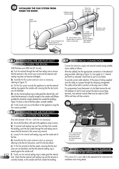
15INSTALLING THE FLUE SYSTEM FROMINSIDE THE ROOMINTERNAL WALLSEALING RING1<strong>30</strong>mm Dia.HOLE WITHWALL LINER•TOP•FIBRESEAL FITTED•••EXTERNAL WALLSEALING RING2 ALIGN ASSEMBLED FLUESYSTEM ELBOW TOAPPLIANCE AND SECURE3 SLIDE INTERNAL WALLSEALING RING TO WALL TOFORM A GOOD SEAL1 INSERTASSEMBLED FLUESYSTEM FROMINSIDE THEROOM. EXTERNALWALL SEALINGRING OPENS•184.8.1 INSTALLING THE AIR/FLUE DUCTFROM INSIDE THE ROOMWall thickness up to 800 mm (31 in) only.a) Push the terminal through the wall liner taking care to ensurethat the terminal is the correct way round and the external wallsealingring does not become dislodged.b) Assemble the flue system extension ducts as necessary,referring to Figure 15.c) Pull the flue system towards the appliance to seat the externalsealing ring against the outside wall, ensuring that the duct jointsare not disturbed.D) Use the internal sealing ring to make good the internal hole, andcheck that the terminal is correctly located on the outside wall (Wherepossible this should be visually checked from outside the building.)Figure 16 shows a view of the flue system, correctly installed.e) Finally locate and secure the elbow to the appliance using thefour screws provided.4.8.2 INSTALLING THE AIR/FLUE DUCTFROM OUTSIDE THE ROOM(Flue hole diameter 100 mm - wall liner not necessary)a) Secure the flue elbow with seal to the appliance using 4 screws.b) Fit external wall sealing ring over flue and then from outsidethe building, push the flue system through the wall taking care toensure that the terminal is the correct way around.c) Loosely fit the internal wall sealing ring over the inside end ofthe flue.d) Assemble the flue system extension ducts as necessary,referring to the flue kit instructions, and fit to the flue elbow.e) Fit the flue terminal to the flue system, ensuring that the ductjoints are not disturbed, and that the external sealing ring isseated against the outside wall.f) Finally use the internal sealing ring to make good the internalhole. Check that the external wall sealing ring and the terminal iscorrectly located, on the outside wall from outside the building.4.9 ELECTRICAL CONNECTIONSConnect the electricity supply and external controls (using suitablemains cable) as follows:Wire the cable(s) into the appropriate connections in the electricalplug provided, referring to Figure 16. Live supply to L1, Neutraland Earth as indicated. Check that L2 and L3 are linked.To provide correct cable retention, fit the piece of tubing suppliedover the cable as it passes through the clamping arrangement.The cable will be held in position as the plug cover is fitted.If a programmer/room thermostat is to be fitted remove the redlink between L2 and L3 and connect the device across theseterminals. Any external controls fitted must be rated at 2<strong>30</strong>V50Hz and have volt free contacts.16Note: If room thermostatis to be fitted removethe link and connectroom thermostat acrossL2 and L3.4.10 OPTIONAL CYLINDER / TANK TEMPERATURESENSOR (<strong>SBX</strong> APPLIANCES ONLY)If this sensor kit is used, refer to the separate kit for instructions forinstallation and wiring details.