
You also want an ePaper? Increase the reach of your titles
YUMPU automatically turns print PDFs into web optimized ePapers that Google loves.
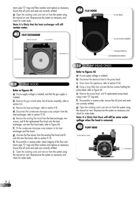
eturn pipe 'O' rings and fibre washers and replace as necessary.Ensure that all joints and seals are correctly re-fitted.q) Open the isolating cocks and vent air from the system usingthe manual air vent. Re-pressurise the system as necessary andcheck for water leaks.Note: It is likely that the heat exchanger will stillcontain water.44 FLUE HOOD43 HEAT EXCHANGER9.10 PUMP (HEAD ONLY)9.9 FLUE HOODRefer to Figures 44a) Ensure supply voltage is isolated, and that the gas supply isisolated.b) Remove the gas control valve, fan & burner assembly; refer tosection 6.2.c) Remove the heat exchanger: refer to section 9.8.d) Disconnect the condensate drainpipe sump adaptor from theheat exchanger; refer to section 9.18.e) Remove the existing flue hood from the heat exchanger, twoscrews, and fit the replacement flue hood onto the heatexchanger; use new flue hood seals; refer to Figure 44.f) Fit the condensate drainpipe sump adaptor to the heatexchanger and flue hood.g) Unscrew the flue sensor from the existing flue hood and fitonto the new flue hood; refer to section 9.16.h) Re-assemble in reverse order; check integrity of the flow andreturn pipe 'O' rings and fibre washers and replace as necessary.Ensure that all joints and seals are correctly re-fitted.i) Open the isolating cocks and vent air from the system usingthe manual air vent. Re-pressurise the system as necessary andcheck for water leaks.Refer to Figures 45a) Ensure supply voltage is isolated.b) Disconnect the electrical lead to the pump head.c) Drain down the appliance; refer to section 9.<strong>24</strong>.d) Using a long Allen key unscrew the four screws holding thepump head; refer to Figure 45.e) Remove the pump head, and fit replacement pump head,using a new 'O' ring seal.f) Re-assemble in reverse order; ensure that all joints and sealsare correctly re-fitted.g) Open the isolating cocks and vent air from the system usingthe manual air vent. Re-pressurise the system as necessary andcheck for water leaks.Note: It is likely that there will still be some waterspillage when the head is removed.45 PUMP HEAD34