

2000 - Draper Laboratory
2000 - Draper Laboratory
2000 - Draper Laboratory
- No tags were found...

You also want an ePaper? Increase the reach of your titles
YUMPU automatically turns print PDFs into web optimized ePapers that Google loves.
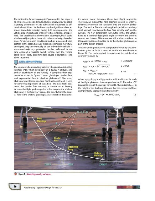
The motivation for developing ALIP presented in this paper isto: (1) decrease design time, and (2) eventually allow onboardtrajectory generation to add substantial robustness to offnominalconditions. In the first case, the algorithms allow analmost immediate redesign during X-34 development as thevehicle properties change or as new initial conditions are specified.This capability has obvious cost advantages, but it couldalso be used just prior to launch in order to redesign the referencesfor day-of-launch conditions (such as a measured windprofile). In the second case, as these algorithms are more fullydeveloped, they can eventually be put onboard the vehicle. Ifautomated trajectory generation can be performed in realtime onboard a reusable launch vehicle, then the vehiclecould more easily accommodate severe disturbances andabort situations.AUTOLANDING OVERVIEWThe unpowered autolanding trajectory begins at AutolandingInterface (ALI), which is typically at a 10,000-ft altitude, andends at touchdown on the runway. It comprises three segments,as shown in Figure 2: steep glideslope, circular flare,and exponential flare to shallow glideslope. [1] The steepglideslope maintains a constant flight path angle and is usedfor removing dispersions at transition. The next flight segment,the circular flare, employs a circular arc to linearlyincrease the flight path angle from the steep to the shallowglideslope. If the trajectory proceeded directly from the circularflare to the shallow glideslope, an acceleration discontinuitywould occur between these two flight segments.Therefore, an exponential flare segment is used in order todynamically smooth the transition onto the shallow glideslope.The vehicle flies the shallow glideslope (with a relativelysmall vertical velocity) until a final flare sets the craft on therunway. The X-34 differs from the Shuttle in that the vehicleflares to a terminal flight path angle to control the descentrate on touchdown. This maneuver will not be considered inthis paper, but is easily added on to the shallow glideslope aspart of the design process.The autolanding trajectory is completely defined by the parametersgiven in Table 1 (most of which are also shown inFigure 2). The mathematical description of the autolandinggeometry is given bywhere h STEEP ,h CIRC , and h EXP are the vehicle altitudes for eachof the flight phases at downrange distance, X. The value of Xis equal to zero at the runway threshold. The variable h SHAL isthe height of the shallow glideslope that the exponential flareasymptotically approaches and is given byh SHAL = (X - XAIMPT) tan γ 2 (2)(1)Figure 2. Autolanding geometry and phases.16Autolanding Trajectory Design for the X-34


