POWERING THE I/O NETWORK ELECTRONICSThe sensors and actuation control devices that make up thenetwork require electrical power to operate. For sensors, poweris used to power the sensor and the terminal used to transmitits data. In the case of actuators, two types of power areneeded: power to operate low-power actuator control electronicsand the network data terminal, and power to operatethe actuator. Several options for delivering power to networkI/O terminals are:• Tap into the nearest source of ship’s power.• Distribute power as part of the data network.• Power the devices with batteries or other wireless sources.The strengths and weaknesses of each option are compared.As before, advantages are preceded by a plus (+) sign and disadvantagesare preceded by a minus (-) sign.Connect Network to Nearest Ship's Power+ Established practice.+ Unlimited power available.+ Power already needed by network I/O actuators.- Ship’s power can become a network I/O single point of failure.- If network I/O controls the power (a desired capability), failurescan cascade.- Wiring to ship’s power is expensive to install.- Ship’s power can transmit EMI or transient dropouts into thedata system.Dedicated Wiring as Part of I/O Network+ Combine installation of data and power wiring.+ Provides sensors with dedicated, uninterruptible power.+ Can power up sensors and actuation control for checkoutprior to applying main power.+ Allows actuator node to detect/report problems with actuationpower.- Adds wires or increases wire gauge, may constrain maximumsize of an I/O network.Battery+ Network devices are very easy to install.- Requires periodic battery replacement.- Limited power available.- Batteries may be large and temperature sensitive.- Many battery chemistries are explosive, corrosive, andexpensive.A preliminary conclusion, at least for sensors, is that includingpower distribution along with the data network offers thebest combination of ease of installation, network dependability,and system maintainability. This option becomes particularlyattractive if the same electrical conductors can be usedfor both the power and the data.I/O NETWORK TOPOLOGYSelecting an appropriate topology for the I/O network is animportant design consideration. Two viable topologies arethe ring and the bus. These two options are illustrated inFigure 3. Examined closely, the ring topology consists of aseries of dedicated, one-way data links from each terminal tothe next. Ultimately, the last terminal is linked to the first toform a ring. Data are sent from terminal to terminal by havingeach terminal rebroadcast any message that is not directed toit to the next terminal until the final destination is reached.The terminal that receives the message "absorbs" it; that is, itdoes not rebroadcast it. As an example, for terminal A to senda message to terminal B, it sends the message to terminal C onthe link from A to C, then terminal C rebroadcasts the messageto terminal B. A primary motivation for using a ring topologyis that each time the message is rebroadcast, its signalstrength is restored. This is ideal for fiber-optic media, whereeach physical terminal connection could otherwise attenuatethe signal until it became too weak to be received.Figure 3.Ring and bus topologies.RingTopologyBusTopologyIn contrast, the bus architecture uses a common physical link,the "bus," to connect all terminals to each other. Terminalsmust take turns using the bus to transmit messages directly toanother terminal(s). A subtle advantage of the bus over thering is that the bus can convey power as well as data to eachterminal on the bus. Table 4 makes a few comparisonsbetween the single-channel nonredundant ring and singlechannelbus topologies shown in Figure 3.Table 4 highlights that a number of single failures can disablethe entire network. For critical functions, this is unacceptable.To overcome vulnerability to single failures, redundancy isintroduced. For the ring topology, a proven approach is theuse of a redundant, counter-rotating ring and the addition ofa special switch that will bypass the terminal should the terminalfail or have its power interrupted (Figure 4). If a link isbroken, a terminal must detect this and reroute data throughFault-Tolerant Input/Output (I/O) Networks Applied to Ship Control 29
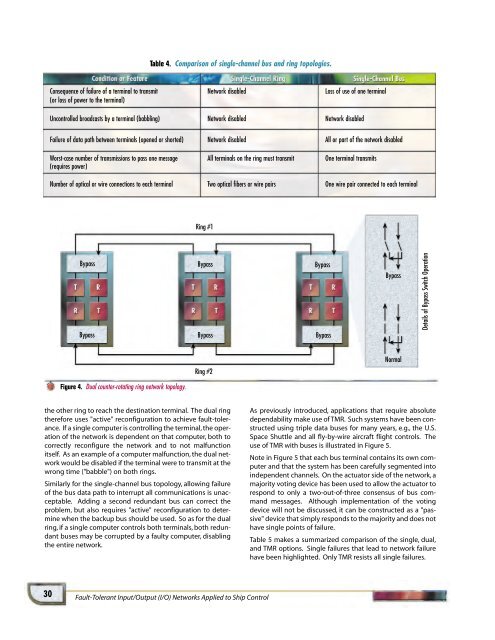
Table 4. Comparison of single-channel bus and ring topologies.Consequence of failure of a terminal to transmit Network disabled Loss of use of one terminal(or loss of power to the terminal)Uncontrolled broadcasts by a terminal (babbling) Network disabled Network disabledFailure of data path between terminals (opened or shorted) Network disabled All or part of the network disabledWorst-case number of transmissions to pass one message All terminals on the ring must transmit One terminal transmits(requires power)Number of optical or wire connections to each terminal Two optical fibers or wire pairs One wire pair connected to each terminalRing #1BypassBypassBypassBypassBypassBypassBypassDetails of Bypass Switch OperationNormalRing #2Figure 4. Dual counter-rotating ring network topology.the other ring to reach the destination terminal. The dual ringtherefore uses "active" reconfiguration to achieve fault-tolerance.If a single computer is controlling the terminal, the operationof the network is dependent on that computer, both tocorrectly reconfigure the network and to not malfunctionitself. As an example of a computer malfunction, the dual networkwould be disabled if the terminal were to transmit at thewrong time ("babble") on both rings.Similarly for the single-channel bus topology, allowing failureof the bus data path to interrupt all communications is unacceptable.Adding a second redundant bus can correct theproblem, but also requires "active" reconfiguration to determinewhen the backup bus should be used. So as for the dualring, if a single computer controls both terminals, both redundantbuses may be corrupted by a faulty computer, disablingthe entire network.As previously introduced, applications that require absolutedependability make use of TMR. Such systems have been constructedusing triple data buses for many years, e.g., the U.S.Space Shuttle and all fly-by-wire aircraft flight controls. Theuse of TMR with buses is illustrated in Figure 5.Note in Figure 5 that each bus terminal contains its own computerand that the system has been carefully segmented intoindependent channels. On the actuator side of the network, amajority voting device has been used to allow the actuator torespond to only a two-out-of-three consensus of bus commandmessages. Although implementation of the votingdevice will not be discussed, it can be constructed as a "passive"device that simply responds to the majority and does nothave single points of failure.Table 5 makes a summarized comparison of the single, dual,and TMR options. Single failures that lead to network failurehave been highlighted. Only TMR resists all single failures.30Fault-Tolerant Input/Output (I/O) Networks Applied to Ship Control
- Page 6 and 7: V 0 e jωt L R R R TL: (Z 0 ,β,I)C
- Page 9 and 10: Figure 16 shows a fabricated "race-
- Page 11 and 12: ACKNOWLEDGMENTS LEDGMENTSThe author
- Page 13 and 14: aanan MillerRaanan Miller is a Seni
- Page 15 and 16: The motivation for developing ALIP
- Page 17 and 18: (4)where the state variables v and
- Page 19 and 20: q’ = f 1 (q, α, h) (26)q = f 2 (
- Page 21 and 22: 4000Computed Altitude (ft)300020001
- Page 23 and 24: eg H. Bartonbiographies biographies
- Page 25 and 26: ActuatorsSensorsIntelligent Sensors
- Page 27: Table 2. Potential sensors requirin
- Page 31 and 32: Using many small I/O networks will
- Page 33 and 34: Network Control ComputersTriple Twi
- Page 35 and 36: Kaplesh KumarAnthony PetrovichTommy
- Page 37 and 38: DESIGN CONSIDERATIONSThe overall go
- Page 39 and 40: BIAS DRIFT STABILITYAn important re
- Page 41 and 42: Hz291206002912050029120400291203002
- Page 43 and 44: In order to show bias repeatability
- Page 45 and 46: nthony PetrovichAnthony Petrovich i
- Page 47 and 48: Ramses M. AgustinRami S. MangoubiRo
- Page 49 and 50: v k is the sensor noise. In our cas
- Page 51 and 52: The preceding performance criterion
- Page 53 and 54: JET THRUST ESTIMATIONWe will first
- Page 55 and 56: 1st measurement (nominal)0.010.0050
- Page 57 and 58: 45004000350030002500Thrust (lb)2000
- Page 59 and 60: amses AgustinbiographiesRamses Agus
- Page 61 and 62: Jamie M. AndersonPeter A. Kerrebroc
- Page 63 and 64: Figure 1. The Draper Laboratory VCU
- Page 65 and 66: were adjusted to give good tracking
- Page 67 and 68: 80604020Heading (deg)0-20-40-60-800
- Page 69 and 70: Marc S. WeinbergII:"'JI.m-4..... 7.
- Page 71 and 72: where z i is measured from the arbi
- Page 73 and 74: L = beam lengthC = capacitance of e
- Page 75 and 76: 3.02.52.0F/z ratio to linear1.51.00
- Page 77 and 78: The following pages contain the bib
- Page 79 and 80:
errors. Numerical testing based on
- Page 81 and 82:
of which are high performance and p
- Page 83 and 84:
presented.The economic benefits of
- Page 85 and 86:
over conventional analyzers. A plan
- Page 87 and 88:
Smith, J.; Proulx, R.J.; Cefola, P.
- Page 89 and 90:
using a dissolved wafer process wit
- Page 91 and 92:
Donald E. GustafsonDavid J. LuciaAu
- Page 93 and 94:
onald E. GustafsonbiographiesDonald
- Page 95 and 96:
Greiff, Paul; Brezinski, PaulGetter
- Page 97 and 98:
DOCTOR ROBERT D. MAURERDr. Maurer l
- Page 99 and 100:
All Draper employees (excluding Off
- Page 101:
Chauddhry, A.I.; Supervisors: Kang,