Robert HammettFault-Tolerant Input/Output (I/O) NetworksApplied to Ship ControlReprinted, with permission, from the Proceedings of the 12th Ship Control Systems Symposium held in the Hague, Netherlands, October 10-21, 1999Future ships will require sophisticated onboard control systems tocontrol machinery, automate tasks, optimize subsystem performance,and simplify maintenance. These controls will exploit theavailability of inexpensive computer processing, will use manysensors and actuation devices, and will provide for completelyintegrated and coordinated control of all subsystems. The crew'sincreased reliance on these automated functions makes it essentialthat they provide dependable operation despite equipmentfailure or battle damage, e.g., they must be fault tolerant anddamage survivable. An example of such a system is the U.S.Navy Seawolf submarine ship control. But the redundant sensorsand actuation systems used on Seawolf, with their associated electronicsand wiring, must be made more compact and affordablefor the approach to find widespread use on future ships. Thispaper describes how the use of data buses, intelligent sensors,and fault-masking actuation electronics can be used to constructInput/Output (I/O) networks that provide flexibility and growth,and that are highly dependable, affordable, and easily installed.These I/O networks can make widespread use of fault- and damage-tolerantsystems practical. The use of I/O networks complementsother efforts to make greater use of electrical actuationaboard ships. This paper explores the requirements for such systemsand examines some of the technology trade-offs that mustbe made, such as network media type (i.e., optical fiber, wired, orwireless), power distribution to network electronics, networktopology (ring or bus), network size vs speed, distributed vs centralizedI/O processing, and cross connections between I/O channels.The paper concludes by describing a concept for afault-tolerant network I/O system and discusses the steps neededto develop such systems for future ships.ntroductionShip Designers have already done much to place moderninformation systems aboard ships. The U.S. Navy Smartship andother projects have shown that it is both possible and beneficialto interface with and merge data from many of the ship's subsystems.[1] These high-level information networks make it possiblefor a small crew located in a central control room to monitorand control subsystems throughout the ship. But this alone doesnot make it possible to operate the ship with a small crew. Today,subsystems throughout the ship are manned to allow thesecrews to assume manual control and make repairs should battledamage or failures occur. Before these subsystems can be operatedunmanned, their dependability and damage survivabilitymust be improved substantially.The techniques for constructing highly dependable electroniccontrols have been established by applications such as fly-bywireaircraft flight controls. These same techniques were appliedsuccessfully to the U.S. Navy Seawolf submarine ship control. [2]The basic approach is to use physically redundant electronicsand a fault-tolerant digital controller with sophisticated softwareto detect faults and reconfigure to use the redundancy, allowingthe system to operate despite equipment failure or damage. Theproblem with widespread application of the approach used onSeawolf is cost and complexity. Modern ships already incorporatea myriad of wiring, junction boxes, electronic racks, and computersthat are difficult and costly to install and maintain.Duplicating, triplicating, or quadrupling this equipment to provideredundancy for fault tolerance is not practical.At least a partial solution to this problem can be found by theincreased use of data multiplexing and highly miniaturized electronicsplaced within intelligent sensors and actuators. Since thesensors and actuators are now part of a network of input andoutput devices, we refer to this arrangement as network I/O. Thedifference between a traditional system and a system that usesnetwork I/O is illustrated in Figure 1.Fault-Tolerant Input/Output (I/O) Networks Applied to Ship Control 25
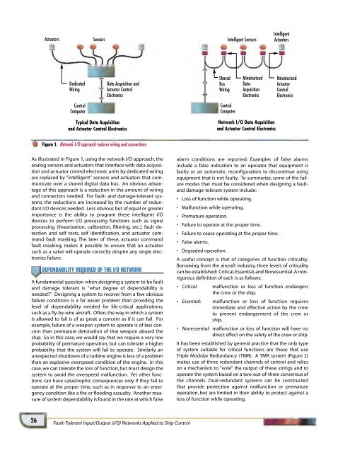
ActuatorsSensorsIntelligent SensorsIntelligentActuatorsDedicatedWiringData Acquisition andActuator ControlElectronicsSharedBusWiringMiniaturizedDataAcquisitionElectronicsMiniaturizedActuatorControlElectronicsControlComputerControlComputerTypical Data Acquisitionand Actuator Control ElectronicsNetwork I/O Data Acquisitionand Actuator Control ElectronicsFigure 1. Network I/O approach reduces wiring and connections.As illustrated in Figure 1, using the network I/O approach, theanalog sensors and actuators that interface with data acquisitionand actuator control electronic units by dedicated wiringare replaced by "intelligent" sensors and actuators that communicateover a shared digital data bus. An obvious advantageof this approach is a reduction in the amount of wiringand connectors needed. For fault- and damage-tolerant systems,the reductions are increased by the number of redundantI/O devices needed. Less obvious but of equal or greaterimportance is the ability to program these intelligent I/Odevices to perform I/O processing functions such as signalprocessing (linearization, calibration, filtering, etc.), fault detectionand self tests, self identification, and actuator commandfault masking. The later of these, actuator commandfault masking, makes it possible to ensure that an actuatorsuch as a valve will operate correctly despite any single electronicsfailure.DEPENDABILITY REQUIRED OF THE I/O NETWORKA fundamental question when designing a system to be faultand damage tolerant is "what degree of dependability isneeded?" Designing a system to recover from a few obviousfailure conditions is a far easier problem than providing thelevel of dependability needed for life-critical applications,such as a fly-by-wire aircraft. Often, the way in which a systemis allowed to fail is of as great a concern as if it can fail. Forexample, failure of a weapon system to operate is of less concernthan premature detonation of that weapon aboard theship. So in this case, we would say that we require a very lowprobability of premature operation, but can tolerate a higherprobability that the system will fail to operate. Similarly, anunexpected shutdown of a turbine engine is less of a problemthan an explosive overspeed condition of the engine. In thiscase, we can tolerate the loss of function, but must design thesystem to avoid the overspeed malfunction. Yet other functionscan have catastrophic consequences only if they fail tooperate at the proper time, such as in response to an emergencycondition like a fire or flooding casualty. Another measureof system dependability is found in the rate at which falsealarm conditions are reported. Examples of false alarmsinclude a false indication to an operator that equipment isfaulty or an automatic reconfiguration to discontinue usingequipment that is not faulty. To summarize, some of the failuremodes that must be considered when designing a faultanddamage-tolerant system include:• Loss of function while operating.• Malfunction while operating.• Premature operation.• Failure to operate at the proper time.• Failure to cease operating at the proper time.• False alarms.• Degraded operation.A useful concept is that of categories of function criticality.Borrowing from the aircraft industry, three levels of criticalitycan be established: Critical, Essential, and Nonessential. A nonrigorousdefinition of each is as follows:• Critical: malfunction or loss of function endangersthe crew or the ship.• Essential: malfunction or loss of function requiresimmediate and effective action by the crewto prevent endangerment of the crew orship.• Nonessential: malfunction or loss of function will have nodirect effect on the safety of the crew or ship.It has been established by general practice that the only typeof system suitable for critical functions are those that useTriple Modular Redundancy (TMR). A TMR system (Figure 2)makes use of three redundant channels of control and relieson a mechanism to "vote" the output of these strings and tooperate the system based on a two-out-of-three consensus ofthe channels. Dual-redundant systems can be constructedthat provide protection against malfunction or prematureoperation, but are limited in their ability to protect against aloss of function while operating.26Fault-Tolerant Input/Output (I/O) Networks Applied to Ship Control
- Page 6 and 7: V 0 e jωt L R R R TL: (Z 0 ,β,I)C
- Page 9 and 10: Figure 16 shows a fabricated "race-
- Page 11 and 12: ACKNOWLEDGMENTS LEDGMENTSThe author
- Page 13 and 14: aanan MillerRaanan Miller is a Seni
- Page 15 and 16: The motivation for developing ALIP
- Page 17 and 18: (4)where the state variables v and
- Page 19 and 20: q’ = f 1 (q, α, h) (26)q = f 2 (
- Page 21 and 22: 4000Computed Altitude (ft)300020001
- Page 23: eg H. Bartonbiographies biographies
- Page 27 and 28: Table 2. Potential sensors requirin
- Page 29 and 30: Table 4. Comparison of single-chann
- Page 31 and 32: Using many small I/O networks will
- Page 33 and 34: Network Control ComputersTriple Twi
- Page 35 and 36: Kaplesh KumarAnthony PetrovichTommy
- Page 37 and 38: DESIGN CONSIDERATIONSThe overall go
- Page 39 and 40: BIAS DRIFT STABILITYAn important re
- Page 41 and 42: Hz291206002912050029120400291203002
- Page 43 and 44: In order to show bias repeatability
- Page 45 and 46: nthony PetrovichAnthony Petrovich i
- Page 47 and 48: Ramses M. AgustinRami S. MangoubiRo
- Page 49 and 50: v k is the sensor noise. In our cas
- Page 51 and 52: The preceding performance criterion
- Page 53 and 54: JET THRUST ESTIMATIONWe will first
- Page 55 and 56: 1st measurement (nominal)0.010.0050
- Page 57 and 58: 45004000350030002500Thrust (lb)2000
- Page 59 and 60: amses AgustinbiographiesRamses Agus
- Page 61 and 62: Jamie M. AndersonPeter A. Kerrebroc
- Page 63 and 64: Figure 1. The Draper Laboratory VCU
- Page 65 and 66: were adjusted to give good tracking
- Page 67 and 68: 80604020Heading (deg)0-20-40-60-800
- Page 69 and 70: Marc S. WeinbergII:"'JI.m-4..... 7.
- Page 71 and 72: where z i is measured from the arbi
- Page 73 and 74: L = beam lengthC = capacitance of e
- Page 75 and 76:
3.02.52.0F/z ratio to linear1.51.00
- Page 77 and 78:
The following pages contain the bib
- Page 79 and 80:
errors. Numerical testing based on
- Page 81 and 82:
of which are high performance and p
- Page 83 and 84:
presented.The economic benefits of
- Page 85 and 86:
over conventional analyzers. A plan
- Page 87 and 88:
Smith, J.; Proulx, R.J.; Cefola, P.
- Page 89 and 90:
using a dissolved wafer process wit
- Page 91 and 92:
Donald E. GustafsonDavid J. LuciaAu
- Page 93 and 94:
onald E. GustafsonbiographiesDonald
- Page 95 and 96:
Greiff, Paul; Brezinski, PaulGetter
- Page 97 and 98:
DOCTOR ROBERT D. MAURERDr. Maurer l
- Page 99 and 100:
All Draper employees (excluding Off
- Page 101:
Chauddhry, A.I.; Supervisors: Kang,