EN 14766:2005 - 64_e_stf - Baltik vairas
EN 14766:2005 - 64_e_stf - Baltik vairas
EN 14766:2005 - 64_e_stf - Baltik vairas
- No tags were found...

You also want an ePaper? Increase the reach of your titles
YUMPU automatically turns print PDFs into web optimized ePapers that Google loves.
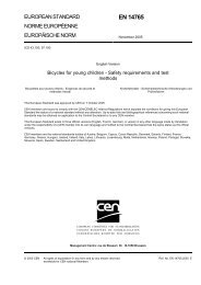
<strong>EN</strong> <strong>14766</strong>:<strong>2005</strong> (E)rely on flexing, ensure that any dampers are set to provide the minimum resistance in order to ensure adequatetesting of the frame.Where a suspension frame has adjustable brackets or linkages to vary the resistance of the bicycle against theground-contact forces or to vary the attitude of the bicycle, arrange the positions of these adjustable components toensure maximum forces in the frame.Key1 Free-running guided roller2 Rigid, pivoted mounting for rear axle attachment point4.8.5.2 RequirementFigure 30 — Frame – fatigue test with horizontal forcesWhen tested by the method described in 4.8.5.3, there shall be no visible cracks or fractures in the frame and thereshall be no separation of any parts of any suspension system.For carbon-fibre frames, the peak deflections during the test in either direction from the mean position shall notincrease by more than 20 % of the initial values.4.8.5.3 Test methodMount the frame in its normal attitude and secured at the rear drop-outs so that it is not restrained in a rotary sense(i.e. preferably by the rear axle) as shown in Figure 30. Ensure that the axes of the front and rear axles arehorizontally in line.Apply cycles of dynamic, horizontal forces of +1 200 N in a forward direction and -600 N in a rearward direction tothe front fork drop-outs for 50 000 cycles as shown in Figure 30, with the front fork constrained in vertical directionbut free to move in a fore/aft direction under the applied forces. The maximum frequency shall be 25 Hz.4.8.6 Frame – fatigue test with a vertical force4.8.6.1 GeneralAll types of frame shall be tested unless the particular frame has both a top-tube and seat-stays the upper parts ofall of which join the seat-tube within a distance of twice the internal diameter of the seat-tube measured from theupper end of the seat-tube and parallel to the seat-tube axis as shown in Figure 31 a). Where the shape of the topface of the seat-tube is other than a plane section perpendicular to the axis of the seat tube, the measurementsfrom the top-tube and the seat-stays (d 1 and d 2 in Figure 31) shall be made to the lowest part of the top edge of theseat-tube (see examples b) and c) Figure 31 c)).51