- Page 1 and 2: PCM-9577Socket 370 Celeron/ Pentium
- Page 3 and 4: Packing ListBefore you begin instal
- Page 5 and 6: ContentsChapter 1 Introduction ....
- Page 7 and 8: 4.2.3 Advanced BIOS Features setup
- Page 9 and 10: Appendix D System Assignments .....
- Page 11 and 12: CHAPTER1General InformationThis cha
- Page 13 and 14: 1.2 Features• Socket 370 supports
- Page 15 and 16: • Power requirements:Max10A @ +5V
- Page 17 and 18: CHAPTER2InstallationThis chapter ex
- Page 19 and 20: Table 2.2: ConnectorsCN7 Peripheral
- Page 21 and 22: 2.4 Locating ConnectorsPCM-9577 REV
- Page 23 and 24: 2.6 Clear CMOS (JP4)Warning!To avoi
- Page 25 and 26: 2.9 Solid State DiskThe PCM-9577 pr
- Page 27 and 28: 2.13.2 Reset switch (J1)If you inst
- Page 29 and 30: 2.17.2 CD audio input connector (CN
- Page 31 and 32: 2.19.5 Panel type selection (S1)S1
- Page 33 and 34: Table 2.6: LAN controller power sel
- Page 35 and 36: * Reliability. Mini PCI Cards will
- Page 37 and 38: III. 3.3 Type II/III Form Factor2nd
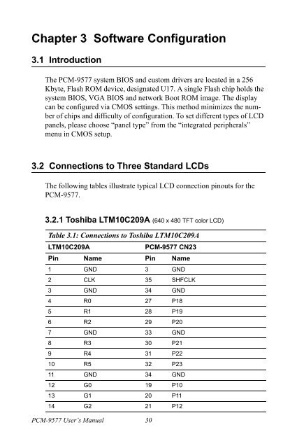
- Page 39: CHAPTER3Software ConfigurationThis
- Page 43 and 44: Table 3.3: Connections to Toshiba L
- Page 45 and 46: 4Chapter Ducks that Need Love!CHAPT
- Page 47 and 48: 4.2 Award BIOS setupAward’s BIOS
- Page 49 and 50: 4.2.3 Advanced BIOS Features setupB
- Page 51 and 52: 4.2.5 Integrated PeripheralsChoosin
- Page 53 and 54: 4.2.9 Frequency/Voltage ControlBy c
- Page 55 and 56: 3. At the “Confirm Password” pr
- Page 57 and 58: CHAPTER5PCI SVGA SetupIntroductionI
- Page 59 and 60: 5.1.4 Dual/Simultaneous DisplayThe
- Page 61 and 62: 2. Choose the "Adapter" tab, then p
- Page 63 and 64: 6. "S3 GraphicsTwister" appears und
- Page 65 and 66: 2. Select “Adapter,” then “Ch
- Page 67 and 68: 5. Insert the CD into the CD-ROM dr
- Page 69 and 70: 5.2.3 Installation for Windows NTNo
- Page 71 and 72: 3. Press the "Change..." button.61
- Page 73 and 74: 6. Select the highlighted item, and
- Page 75 and 76: 2. Choose the "Video Controller (VG
- Page 77 and 78: 4. Choose "Display a list of..." ,
- Page 79 and 80: 8. Press “Finish" to reboot.5.2.5
- Page 81 and 82: 3. Choose “Video Controller (VGA
- Page 83 and 84: 6. Choose “Don’t search. I will
- Page 85 and 86: 10. Press “Finish" to reboot.5.3
- Page 87 and 88: CHAPTER6Audio SetupThe PCM-9577 is
- Page 89 and 90: 6.2.2 VIA Sound Blaster Installatio
- Page 91 and 92:
3. In the following Add New Hardwar
- Page 93 and 94:
7. In the following Add New Hardwar
- Page 95 and 96:
11. In the Select Device window, se
- Page 97 and 98:
6.3.3 Windows NT drivers1. Click "S
- Page 99 and 100:
5. In the Add Unlisted or Updated D
- Page 101 and 102:
3. Choose “Driver button, press
- Page 103 and 104:
8. Press “Next” button9. Press
- Page 105 and 106:
CHAPTER7PCI Bus Ethernet InterfaceT
- Page 107 and 108:
7.2.2 Installation for Windows 981.
- Page 109 and 110:
6. a. Choose the " Intel 8255x base
- Page 111 and 112:
2.101 Chapter 7
- Page 113 and 114:
5.6.103 Chapter 7
- Page 115 and 116:
9.7.2.4 Installation for Windows NT
- Page 117 and 118:
4. Click “Have Disk.”5. a. Inse
- Page 119 and 120:
7. Click “Next” to continue set
- Page 121 and 122:
11. Click “Next” to start the n
- Page 123 and 124:
AppendixAProgramming theWatchdog Ti
- Page 125 and 126:
The following example shows how you
- Page 127 and 128:
AppendixBInstalling PC/104ModulesTh
- Page 129 and 130:
Figure B.1: PC/104 module mounting
- Page 131 and 132:
AppendixCPin AssignmentsThis append
- Page 133 and 134:
C.3 Ethernet 10/100/1000 BASE-T con
- Page 135 and 136:
C.6 Main Power Connector (CN9)Table
- Page 137 and 138:
C.8 Floppy Disk Drive Connector (CN
- Page 139 and 140:
Table C.9: PC/104 connectors (ISA1)
- Page 141 and 142:
C.11 Parallel Port Connector (CN17)
- Page 143 and 144:
C.14 USB Connector (CN1, CN2)Table
- Page 145 and 146:
C.18 TV (video) Out Connector (CN20
- Page 147 and 148:
C.20 Extended Flat Panel Display Co
- Page 149 and 150:
C.22 LVDS Connector (CN15)Table C.2
- Page 151 and 152:
C.25 CompactFlash Card Connector (C
- Page 153 and 154:
C.27 GPIO Connector (CN25)Table C.2
- Page 155 and 156:
Table C.28: Mini PCI Connector (CN2
- Page 157 and 158:
AppendixDSystem AssignmentsThis App
- Page 159 and 160:
D.2 1st MB memory mapTable D.2: 1st
- Page 161 and 162:
AppendixEOptional Extras for thePCM
- Page 163 and 164:
E.2 PCM-10586-5G00 Cable kit for PC
- Page 165 and 166:
AppendixFMechanical Drawings
- Page 167 and 168:
PCM-9577 REV.A1Figure F.2: PCM-9577