PCM-9577
PCM-9577
PCM-9577
You also want an ePaper? Increase the reach of your titles
YUMPU automatically turns print PDFs into web optimized ePapers that Google loves.
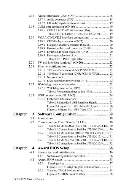
2.17 Audio interfaces (CN5, CN6).......................................... 182.17.1 Audio connector (CN5) ................................................ 182.17.2 CD audio input connector (CN6).................................. 192.18 COM port connector (CN16) .......................................... 192.18.1 COM2 RS-232/422/485 setting (JP6)........................... 19Table 2.4: JP6: COM2 RS-232/422/485 select............. 192.19 VGA/LCD/LVDS interface connections ........................ 202.19.1 CRT display connector (CN22) .................................... 202.19.2 Flat panel display connector (CN23)............................ 202.19.3 Extension flat panel connector (CN18) ........................ 202.19.4 LVDS LCD panel connector (CN15) ........................... 202.19.5 Panel type selection (S1)............................................... 21Table 2.5:S1 Panel Type select.................................... 212.20 TV-out interface (optional) (CN20) ................................ 222.21 Ethernet configuration..................................................... 222.21.1 100Base-T connector (CN3, <strong>PCM</strong>-<strong>9577</strong>F)................... 222.21.2 1000Base-T connector (CN8, <strong>PCM</strong>-<strong>9577</strong>FG).............. 222.21.3 Network boot ................................................................ 222.21.4 LAN controller power select (JP7) ............................... 222.22 Watchdog timer configuration ........................................ 232.22.1 Watchdog timer action (JP5) ........................................ 23Table 2.7:Watchdog timer action (JP5) ........................ 232.23 USB connectors (CN1, CN2).......................................... 242.23.1 Embedded USB interface: ............................................ 24Table 2.8:Embedded USB interface Signals................. 25Figure 2.4:Figure 3-1: USB Module (Type I) ............. 26Figure 2.5:Figure 3-2: USB Type II/III ...................... 27Chapter 3 Software Configuration .................................303.1 Introduction ..................................................................... 303.2 Connections to Three Standard LCDs............................. 303.2.1 Toshiba LTM10C209A (640 x 480 TFT color LCD)... 30Table 3.1:Connections to Toshiba LTM10C209A ....... 303.2.2 Toshiba LTM15C151A (1024 x 768 TFT color LCD). 31Table 3.2:Connections to Toshiba LTM15C151A ....... 313.2.3 Toshiba LTM12C275A (800 x 600 TFT color LCD)... 32Table 3.3:Connections to Toshiba LTM12C275A ....... 32Chapter 4 Award BIOS Setup.........................................364.1 System test and initialization........................................... 364.1.1 System configuration verification................................. 364.2 Award BIOS setup .......................................................... 374.2.1 Entering setup .............................................................. 37Figure 4.1:BIOS setup program initial screen .............. 374.2.2 Standard CMOS Features setup.................................... 38Figure 4.2:CMOS Features setup.................................. 38<strong>PCM</strong>-<strong>9577</strong> User’s Manualvi


