Sauer-Danfoss series OTP steering columns
Sauer-Danfoss series OTP steering columns
Sauer-Danfoss series OTP steering columns
- No tags were found...

You also want an ePaper? Increase the reach of your titles
YUMPU automatically turns print PDFs into web optimized ePapers that Google loves.
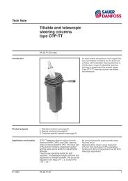
<strong>OTP</strong> Steering Columns / OVPL, OVR Valve BlocksTechnical InformationAdjustable Steering Columns, <strong>OTP</strong>Load on AdjustableSteering ColumnsSymbols:A : Tilt pointL m [in] : Axial length between mounting point and <strong>steering</strong> wheel.E m [in] : Axial length between mounting point and tilt point.B m [in] : Axial length between tilt point and end of body tube.P r N [lbf•in] : Radial force on <strong>steering</strong> wheelP a N [lbf•in] : Axial force on <strong>steering</strong> wheel.MD Nm [lbf•in] : Turning torqueMB Nm [lbf•in] : Bending moment on the <strong>steering</strong> column, MB = P r * LThe following max permissible values must not be exceeded:M D :M B :P a :max 240 Nm [2124 lbf•in]max 200 Nm [1770 lbf•in]max 1000 N. [224.8 lbf]InstallationInstallation of adjustable <strong>steering</strong> <strong>columns</strong>.CautionAlignment of <strong>steering</strong> column and <strong>steering</strong> unit is very important.The <strong>steering</strong> column must be coaxial with the splined connection of the <strong>steering</strong> unit:It must be guaranteed that the shaft of the <strong>steering</strong> column generates no radial and/oraxial forces in the splined connection of the <strong>steering</strong> unit.11015554 • Rev AB • May 200841