NIBE F1330 - Klimats24.lv
NIBE F1330 - Klimats24.lv
NIBE F1330 - Klimats24.lv
- No tags were found...

Create successful ePaper yourself
Turn your PDF publications into a flip-book with our unique Google optimized e-Paper software.
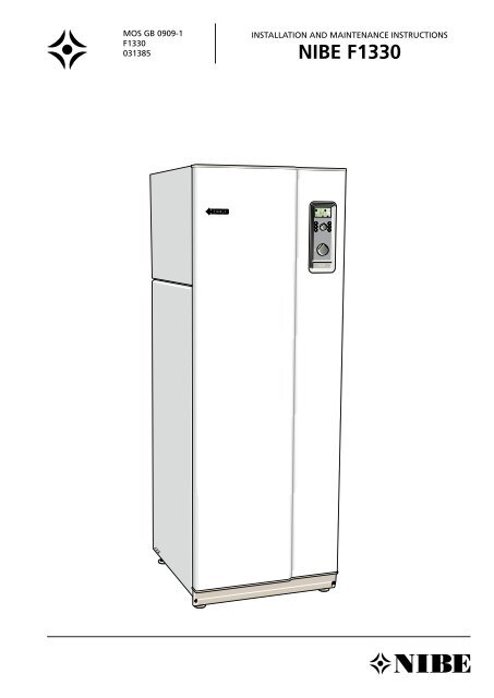
LEKMOS GB 0909-1<strong>F1330</strong>031385INSTALLATION AND MAINTENANCE INSTRUCTIONS<strong>NIBE</strong> <strong>F1330</strong>
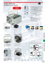
User guideSetting the heating controlsSetting the heating controlsSetting using diagramsThe heating control system of the <strong>F1330</strong> is controlled bythe outside temperature. This means the flow temperatureis regulated in relation to the current outdoor temperature.The relation between the outdoor temperature and flowtemperature is set in menu 2.1, Curve slope.The diagram is based on the dimensioned outdoor temperaturein the area and the dimensioned supply temperatureof the heating system. When these two values meet,the heating control’s curve slope can be read.The Heating curve offset knob is then set on the Masterunit. A suitable value for underfloor heating is -1 and fora radiator system -2.Offset heating curve -2FRAMLEDNINGSTEMPERATURSUPPLY TEMPERATURE+ 5°C7060504030VÄRMEKURVAHEATING CURVE15 14 13 12 11 10987654321- 510 0 - 10OFFSET FÖRSKJUTNING HEATINGCURVE VÄRMEKURVA (-2)- 20 - 30 - 40 °CUTETEMPERATUROUTSIDETEMPERATUREOffset heating curve 0Heatingcurve offsetFRAMLEDNINGSTEMPERATURSUPPLY TEMPERATURE+ 5°C7060504030VÄRMEKURVAHEATING CURVE15 14 13 12 11 10 987654321- 510 0 - 10 - 20 - 30OFFSET FÖRSKJUTNING HEATINGVÄRMEKURVA (0)CURVE- 40 °CUTETEMPERATUROUTSIDETEMPERATUREOffset heating curve +2VÄRMEKURVAHEATING CURVEFRAMLEDNINGSTEMPERATURSUPPLY TEMPERATURE+ 5°C70605040301514 13 12 11 10987654321- 510 0 - 10OFFSET FÖRSKJUTNING HEATINGCURVE VÄRMEKURVA (+2)- 20 - 30 - 40 °CUTETEMPERATUROUTSIDETEMPERATURE<strong>NIBE</strong> <strong>F1330</strong>7
User guide8 <strong>NIBE</strong> <strong>F1330</strong>
Installation / AdjustmentGeneral information for the installerGeneral information for the installerTransport and storageThe <strong>F1330</strong> must be transported and stored upright anddry.InstallationThe <strong>F1330</strong> must be installed on a firm surface, preferablya concrete floor or a concrete foundation in a boiler roomor a separate equipment room. Avoid installing it in oradjacent to a sound-sensitive room. Wherever the unit islocated, any wall that backs on to a bedroom should befitted with sound insulation.Master / SlaveSeveral <strong>F1330</strong>s can be interconnected to work together.This is done by selecting one heat pump as the Master andthe others as Slaves. External units, e.g. oil boiler, are connectedto the Master unit. Each Slave isgiven a unique address for communication with theMaster unit. See the section Description of functions -Start up > Master/Slave.External control (e.g. DUC)<strong>F1330</strong> can be controlled up to a certain pointusing signals from an external system (e.g. DUC).See the section Description of functions - External control.External communication (RCU)The <strong>NIBE</strong> RCU communication unit enables <strong>F1330</strong> to becontrolled and monitored using a computer or a principlesystem (SCADA-system), which can read the ModbusTCPprotocol,in a local network or via the internet.The integrated GSM module also enables control andmonitoring by sending text messages from a mobilephone. In the event of an alarm, the RCU can send SMS/Emailsto the programmed recipient. For the GSM functionto work in the RCU, the communications module must beequipped with a valid GSM subscription. This may for examplebe a cash card or a special telematics subscription.It is possible to connect two independent switch functionsto the RCU to detect external events such as a movementalarm or freezing protection.CollectorsTypeNOTE!Soil heatrecommendedcollector lengthRock heatrecommended activedrilling depth22 3 x 350 - 4 x 400 m 2 x 180 - 3 x 180 m30 3 x 450 - 4 x 450 m 3 x 150 - 5 x 150 m40 4 x 500 - 6 x 500 m 4 x 170 - 5 x 200 m60 6 x 450 - 8 x 450 m 6 x 150 - 8 x 180 mThe maximum length of each loop is 500 metres.The hose normally used is PEM hose 40 x 2.4 PN 6.3.The length of the collector hose varies depending on therock/soil conditions and on the heating system, e.g. radiatorsor underfloor heating.Collectors are always connected in parallel, with somemeans of adjusting the flow.For surface soil heat, the hose should be buried at a depthof about 1 metre and the distance between the hosesshould be at least 1 metre.For rock heat, there must be a distance of at least15 meters between boreholes.Inspection of the installationIn accordance with applicable regulations, heating installationsmust undergo an installation inspection before beingcommissioned. The inspection must be carried out by asuitably qualified person. The above applies to closed heatingsystems. If the heat pump is replaced, the installationmust be inspected again.The sensor and communication cables mustnot be routed closed to the power cable.This applies to all external sensors and allcommunication cables.When cable conduit is used for the outdoorsensor this should be sealed to prevent condensationin the outdoor sensor capsule.<strong>NIBE</strong> <strong>F1330</strong>9
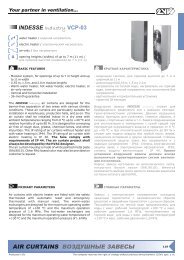
A BA B5 0 . 0 ° CVa r m v a t t e n t e m p e r a t u r1.0 P 13.43I IIInstallation / AdjustmentPipe connectionsPipe connectionsGeneralPipe installation must be carried out in accordance withcurrent norms and directives. <strong>F1330</strong> can work up to areturn temperature of approx. 58 °C and an outgoingtemperature from the heat pump of approx. 65 °C. When<strong>F1330</strong> is not equipped with shut off valves, these mustbe fitted outside of the heat pump to assist future servicework.Pipe connections (heating medium)Pipes are connected at the rear of the heat pump. Thenecessary safety equipment, shutoff valves (fitted as closeas possible to the heat pump), and the particle filter andflexible hoses supplied must be fitted.When connecting to a system with thermostats on allradiators/coils, a relief valve must be fitted, or some of thethermostats must be removed to ensure sufficient flow.The unit is designed to allow hot water production withone or two heat pump modules. However, this requiresdifferent pipework and a different electrical installation.Pipe connections (brine)When dimensioning the collector, consideration mustbe given to the geographical location, type of rock andground and the degree of coverage provided by the heatpump.When installing the collector hose, ensure it rises constantlytowards the heat pump to avoid air pockets. If this is notpossible, install high points to vent the air.All brine pipes in heated rooms must be insulated againstcondensation.As the temperature of the collector system can fall below0 °C it must be protected against freezing down to -15 °C.One litre of ready mixed brine per meter of collector hose(applies when using PEM-hose 40 x 2.4 PN 6.3) is used asa guide value when making the volume calculation.The collector system should to be labelled to show whatantifreeze has been used.Shut-off valves should be installed as close to the heatpump as possible. Fit a particle filter to the incoming pipe.In the case of connection to an open groundwater system,an intermediate frost-protected circuit must be provided,because of the risk of dirt and freezing in the evaporator.This requires an additional heat exchanger.NOTE!The pipe system needs to be flushed outbefore the heat pump is connected so thatdebris cannot damage component parts.This applies to both hot and cold sides.AVBKEXPJKKB-inKB-utSFNOTE!The heat pump’s pipe must not besoldered directly, due to internal sensors.Compression ring or press coupling shouldbe used.Connecting external brine pump (60 kW only)The enclosed external brine pump for <strong>F1330</strong> -60kW isinstalled externally outside the heat pump on incomingconnection (4) (see image above).EXPAVPBK / JKSFShutoff valveRock collectorLevel vesselSoil collectorBrine inBrine outSFKBPKBP*KB-inParticle filterKButKB-inKBut*The brine pump for 60 kW is supplied and installed externally outsidethe heat pump.BABAVVFVBFBVBP-BVVRVBRA/VBRBVBFAVBP-A<strong>NIBE</strong> <strong>F1330</strong>11
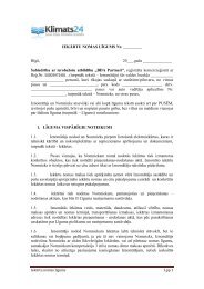
Installation / AdjustmentPipe connectionsPressure expansion vesselThe brine circuit should be fitted with a pressure expansionvessel. If there is a level vessel, this should be replaced. Thebrine side should be pressu rised to at least 0.5 bar.The pressure expansion vessel should be dimensioned asset out in the diagram, to prevent operating disturbances.The pressure expansion vessel covers the temperaturerange from -10 °C to +20 °C at a pre-pressure of 0.5 barand the safety valve’s opening pressure 3 bar.Limiting condenser out and condenser inFor HTF in hotter than -5 °C, limiting of max condenserout 65 °C and max condenser in 58 °C.For HTF in colder than -5 °C, max condenser out and maxcondenser in lowers automatically, according to diagram,additional heat maintains desired supply temperature.For HTF in lower than -8 °C, the compressor stops and thedesired supply temperature is only maintained by additionalheat.Pressure expansionkexpansionskärlvessell60504030201000Brinevolume Köldbärarvolym100 200 300 400 500 600 700 800 900 1000 1100 1200 1300 1400 1500 lCondenser outKondensor ut°C706866164626058256545250-9 -7 -5 -3 -1 1 3 5 7 9 11 13 15 17 19 211. Condenser out 2. Condenser inKöldbärareinBrine in°CAvailable pressure, heating medium sidePressure22 - 30kW Pressure<strong>F1330</strong>-22/30/40kPa40kWkPa<strong>F1330</strong>-6010080907080706060505034034023023020201101 Flow 10Flow000 0,2 0,4 0,6 0,8 1 1,2 l/s0,00 0,20 0,40 0,60 0,80 1,00 1,20 1,40 1,60 1,80 l/sAvailable pressure, collector side (ethanol 28 %)Pressure22 - 30kW Pressure<strong>F1330</strong>-22/30/40kPa40kWkPa<strong>F1330</strong>-60180180160160140140120120100100808060360404032202Flow 201Flow0100 0,2 0,4 0,6 0,8 1 1,2 1,4 1,6 1,8 2 2,2 2,4 l/s0,0 0,5 1,0 1,5 2,0 2,5 3,0 3,5 l/s12 <strong>NIBE</strong> <strong>F1330</strong>
Installation / AdjustmentElectrical connectionElectrical connectionElectrical installationThe cable for incoming power shall enter from the rear asset out in the figure.The sensor inputs and communication connection areof the type SELV. Sensors cables must not be routedtogether with power cables. Cables may be taken outfrom the rear of the heat pump.Cable entry,heavy current(supply)Cable entry,sensorConnection of external sensorsSee respective Description of functions for connection ofexternal sensors.For example, for the flow sensor (FG), return sensor (RG),outdoor sensor (UG) see Description of functions - Basicfunctions > Heat production. For the hot water sensor(VVG), see Description of functions - Basic functions > Hotwater production.NOTE!The sensor and communication cables mustnot be routed close to the power cable.This applies to all external sensors and allcommunication cables.When cable conduit is used for the outdoorsensor this should be sealed to prevent condensationin the outdoor sensor capsule.NOTE!Electrical installation and servicing mustbe carried out under the supervision of aqualified electri cian in accordance with thestipulations in force.1a 1b 26a 26bMiniature circuit-breakerControl, circulation pumps and their wiring, are internallyfuse protected with miniature circuit breakers -F1 (1a) and-F2 (1b).Control is fused by -F1 (1a) and the circulation pumps withtheir cabling are fused by -F2 (1b).ResettingThe miniature circuit breakers -F1 (1a) and -F2 (1b) can beaccessed on the reverse of the heat pump (see image).Motor cut-outThe heat pump is equipped with two motor cut-outs. If thecurrent becomes too high in any of the compressors, themotor cut-outs cut the current to the affected compressor.Motor cut-out -Q1A (26a) cuts the power supply to compressorA.Motor cut-out -Q1B (26B) cuts the power supply to compressorB.ResettingThe motor cut-outs-Q1A (26a) and-Q1B (26b) can be accessedon the reverse of the heat pump (see image). If acut-out deploys, it can be reset by turning the knob to thevertical position.NOTE!Reset the miniature circuit-breaker and themotor cut-out. They may have tripped duringtransportation.<strong>NIBE</strong> <strong>F1330</strong>15
Installation / AdjustmentElectrical connectionConnection A heat pump must not be connected without the permissionof the electricity supplier and must be connectedunder the supervision of a qualified electrician. If an miniature circuit-breaker is used this should havea motor characteristic D (compressor operation). ForMCB size see Technical Specifications. When the building is equipped with an earth-faultbreaker, the heat pump should be equipped with aseparate one The <strong>F1330</strong> does not include an isolator switch on theincoming electrical supply. The installation must be precededby a circuit-breaker with at least a 3 mm breakinggap. If an insulation test is to be carried out in the building,disconnect the heat pump.Sensor cables Connect the heat pump to the terminal block X9, 400V 3-phase, neutral + earth via a distribution board withfuses. Where there is more than one heat pump, eachunit must have a separate supply. Continue the installation by carrying out the inspectionset out in Description of functions - Start up >Inspection. NOTE! It is not permitted to fit additional componentsin the electrical connection area. Note that <strong>F1330</strong> provides 230V control signals thatare intended to control external contactors andnot to drive pumps.164X9, incoming electricity Supply cableLEKThe heat pump in the picture is fitted with accessories.Phase sequence monitor<strong>F1330</strong>- 30, 40, 60 kWThe phase sequence monitor starts as soon as the powersupply is connected to the heat pump. Check the phasesequence as shown below. Orange LED is lit at correct phase sequence. Green LED is lit when there is power. If there is a fault in the phase sequence, the heat pumptriggers a brine alarm in both modules.16 <strong>NIBE</strong> <strong>F1330</strong>
Installation / AdjustmentDescription of functions - Start upDescription of functions - Start upInspectionThis inspection should be done on all heat pumps in thesystem individually. Other heat pumps should be switchedoff when the inspection is made.When <strong>F1330</strong> is switched off during the inspection, theService mode should be reselected from menu 8.1.1 togain access to menus that are not normally accessible.NOTE!<strong>F1330</strong>-60 must be powered and the switchin position 1 for at least 12 hours before thecompressors can be started. This is because thecompressor oil must reach the correct operatingtemperature.If these instructions are not followed there is arisk of seriously damaging the compressors, thisapplies upon first-start up.1. Start the heat pump by turning the power switch (8)to the 1 position. The unit will now enter screen savermode and the text Master will be shown on the bottomrow of the display. When only Connecting flashesthe heat pump this may be because the heat pump isset as a Slave. If so, set the unit as the Master accordingto the instructions in Description of Functions –Start up > Master/Slave.2. Deactivate the screen saver by holding down the buttonin the far left corner and the enter button for approximately8 seconds. (See the section the Descriptionof Functions – Start up > Screensaver.)3. Set in the Service position from menu 8.1.1. (See theexample in Control > Changing parameters.)4. On delivery <strong>F1330</strong> is set with English as the menulanguage, if another language is required this can bechanged in the menu 8.1.2.X95. Start the brine pump (KBP) by setting Continuous inmenu 5.4.6. See the section Description of functions -Basic functions > Brine pump.6. Check that the direction of rotation of the brine pumpagrees with the arrow on the pump. When the directionof rotation is wrong, two of the incoming phaseson terminal block X9 must be switched.7. Start the heating medium pump A (VBP-A) and theheating medium pump B (VBP-B) by setting Continuousin menu 5.4.7 and 5.4.8. See the section Description offunctions - Basic functions > Heating medium pumps.8. Check that the brine and heating medium pumps arevented and if necessary help the pumps to start.9. Go to menu 5.2.2 and check that the temperatures correspondwith the collector temperature, which indicatesthe brine flow.10. Short the inputs KPRAA and KPRAB with their ownstrap.+EBV-card+Measure cardJ5X4LEKThe heat pump in the picture is fitted with accessories.<strong>NIBE</strong> <strong>F1330</strong>17
Installation / AdjustmentDescription of functions - Start up11. Set the heat pump’s operating type to External controlin menu 0.2.1.12. Remove the strap for compressor A (KPRAA).13. Compressor A starts. Note there may be a slight delayof a few minutes before starting. See menu 0.1.1 to seethe time to start.14. Check the temperature difference on the heat mediumin menu 5.2.1. Nominal difference is 5 to 10 °C.15. Check the temperature difference on the brine mediumin menu 5.2.2. Nominal difference is 2 to 5 °C.16. Reset the strap for compressor A (KPRAA).17. Remove the strap for compressor B (KPRAB).18. Compressor B starts. Note there may be a slight delayof a few minutes before starting. See menu 0.1.2 to seethe time to start.19. Check the temperature difference on the heat mediumin menu 5.3.1. Nominal difference is 5 to 10 °C.20. Check the temperature difference on the brine mediumin menu 5.3.2. Nominal difference is 2 to 5 °C.21. Reset the strap for compressor B (KPRAB).22. Reset all settings by selecting Extended in menu 5.4.10.Note that the setting returns to Off as soon as the heatpump has made the factory setting.23. Set the power switch (8) in position ”0”.24. Remove both straps (KPRAA and KPRAB).Start up with a <strong>F1330</strong>1. Start the heat pump by turning the power switch (8)to the 1 position. The unit will now enter screen savermode and the text Master will be shown on the bottomrow of the display.2. When only Connecting flashes the heat pump this maybe because the heat pump is set as a Slave. If so, setthe unit as the Master according to the instructions inDescription of Functions - Start up > Master/Slave.3. Deactivate the screen saver by holding down the buttonin the far left corner and the enter button for approximately8 seconds. (See the section the Descriptionof Functions - Start up > Screensaver.)4. Set in the Service position from menu 8.1.1. (See theexample in Control > Changing parameters.)5. Set the heat pump’s operating type, i.e. whether theheat pump should produce hot water and/or heating.This is done in menu 0.2.1. (See the section Descriptionof Functions - Start up > Operating type selection.)6. Continue the start up settings with the help ofDescription of Functions - Basic Functions. Connect andconfigure the pertinent functions for the installation.When all heat pumps have undergone this inspection,continue with “Description of functions” - “Start up” >“Start up with a <strong>F1330</strong>” or if several <strong>F1330</strong> are connected“Description of functions” - “Start up” > “Start up withseveral <strong>F1330</strong>s in a system”See “Dealing with malfunctions” at the end of thebooklet in the event of any problems at start-up.18 <strong>NIBE</strong> <strong>F1330</strong>
Installation / AdjustmentDescription of functions - Start upStart up with several <strong>F1330</strong>s in a system1. <strong>F1330</strong> is delivered as the Master. Other units in the systemmust be selected as unique slaves. This is done accordingto the instructions in Description of Functions- Start up > Master/Slave. It is extremely important thatthis is done for all units when the following settings aremade.2. Start all the heat pumps by turning the powerswitch (8) to the 1 position. The slaves will now flashConnecting, while the Master is in screen saver mode.3. Deactivate the screen saver on the Master by holdingdown the button in the far left corner and the enterbutton for approximately 8 seconds. (See the sectionthe Description of Functions - Start up > Screensaver.)4. Set the Master in the Service position from menu8.1.1. (See the example in Control > Changing parameters.)5. Set each connected unit’s operating type, i.e. whichpumps should produce hot water and/or heating. Thisis done in menu 0.2.1. (See the section Descriptionof Functions - Start up > ”Operating type selection”.)As long as Off is selected as the operating type, nocommunication with the Slave will occur, however, assoon as the operating type is changed to somethingother than Off, the Slave’s display will stop flashingConnecting and will enter Screen saver mode.6. Check that all connected heat pumps display the correctSlave number on the display. If this is not the case,check that all communication cables are correctly connectedand shutoff all heat pumps. Now restart theSlaves and then the Master. Should the wrong Slavenumber be displayed or a display continues to flashConnecting - start again with the Master/Slave settingsin point 1.7. Continue with the start up settings with the help ofDescription of Functions - Basic Functions. Connectand configure the pertinent functions for the installation.Operating type selectionThe operating type must be selected for each connected<strong>F1330</strong>. This is selected in the sub-menus to 0.2.0 and canbe selected from:Off: Compressor modules A and B are not used. No communicationwith the heat pump.Heat: Compressor modules A and B only provide heating.No shuttle valve necessary.Hot water: Compressor modules A and B only providehot water. No shuttle valve necessary.Combi: Compressor module B provides both hot waterand heating via the shuttle valve, while compressor moduleA always provides heating. The shuttle valve should beinstalled to the flow line on compressor B.Parallel: Compressor modules A and B provide both hotwater and heating via the shuttle valve. The shuttle valveshould be connected to the common flow line for compressorsA and B.External control: Start and stop signal from externalequipment. The shuttle valve can be connected, butshould not be controlled from <strong>F1330</strong>.Screen saverIn screen saver mode, you can see any alarms as well asthe flow temperatures currently given by the compressors(VBFA and VBFB) and whether the heat pump is a Masteror Slave. The screen saver is deactivated by pressingthe enter button and the button in the lower left forapproximately 8 seconds. Menu 1.0 is then displayed.The screen saver comes on automatically 30 minutes afterthe last button was pressed and when starting the heatpump.Exemple:5 4 , 1 5 5 , 7 ° CS l av e 3alt.H P - A L A R MS l av e 3<strong>NIBE</strong> <strong>F1330</strong>19
Installation / AdjustmentDescription of functions - Start upMaster / Slave<strong>F1330</strong> is always delivered as the Master. Up to 8 Slavescan be connected to the Master. Only one heat pump witheach address can be installed in the same system, i. e. onlyone Master and only one Slave 5.External temperature sensors and control signals shouldonly be connected to the Master, with the exception ofthe shuttle valve/s (VXV) which can be connected one oneach heat pump. See the section Description of functions- Start up > Operating type selection for setting, as wellas Description of functions - Basic functions > Hot waterproduction for connecting a shuttle valve (VXV).Should contact between the heat pumps fail, the Masterwill attempt to re-establish communications every tenminutes. During the period of the communication error,the text Com. error will be shown as the status of the heatpump in menu 0.1.x, 5.2.0 and 5.3.0.When starting a system with several heat pumps, theMaster should never be switched on before the Slaves. Ifthis does occur, the Master will not the find the Slaves duringstart up and the Slaves will then not work for up to 10minutes.In order to reset the heat pump between Master and Slave1 – 8, proceed as follows:1. Check that the heat pump is switched off. Disconnectthe communication between the heat pumps. Theeasiest way to do this is to temporarily disconnect themodular cables from the communications card. (fig. 1)2. Set the power switch (8) in position “1”.3. Wait approximately 30 seconds.4. Turn the selector switch marked U6 (fig. 4) on theMeasure card using a small screwdriver so that thearrow points to the required position. 0 refers to aMaster while 1 – 8 refers to Slave 1 – 8. Each Slave isgiven a unique address for communication with theMaster unit.5. Wait approximately 5 seconds and check that the displayshows your selection.Example14U6LEKS l av e 16. Shut down the heat pump by turning the power switch(8) to “0”. The heat pump is now configured to act accordingto the setting.7. Reconnect the modular cables that were disconnectedin step 1.8X4 CableX3 CableConnection of Master/SlaveDaisy-chain the heat pumps by using a screened 3-corecable. Position A on terminal block X4 Cable on the communicationscard (3) should be connected to position A onterminal block X3 Cable on the communications card inthe next heat pump. In the same way, position B and GNDare connected together with the communications card inthe next heat pump.SLAVE 2SLAVE 1MASTERThe heat pump in the picture is fitted with accessories.20 <strong>NIBE</strong> <strong>F1330</strong>
Installation / AdjustmentDescription of functions - Basic functionsDescription of functions - Basic functionsBrine pumpThe operating mode for the brine pump (internally installedin 22 – 40 kW) can be set separately for each heatpump in menu 5.4.6.Connecting external brine pump (60 kW only)Connect the enclosed external brine pump to terminalblock -X7:1-5 (13).Level monitorA level monitor, brine pressostat or flow sensor can beconnected to prevent operation in the event of leakage inthe collector circuit.The status of the input can be checked during operationof the compressor and just prior to compressor start (whenthe brine pump is already in operation).Alarm given as existing and the brine pump is unaffecteduntil the alarm is reset.Level monitor connectionThe level monitor is connected to terminal block X1:16-17.Quick guide - menu settingsLevel monitorNOTE!If the brine pump is not connected correctlyduring startup, the heat pump receives a brinealarm.Menu 5.4.4 Level monitor[U]Select here whether an external brine pressostat, levelmonitor or flow sensor is connected to the “EBVcard”.Can be set to “On (NC)”, “On (NO)” or “Off”.The factory setting is “Off”.If set to ”On (NC)” alarm triggered when input isopened.If set to ”On (NO)” alarm triggered when input is closed.Quick guide - menu settingsBrine pumpMenu 5.4.6 Oper. mode brinepumpThe operating mode for the brine pump is set here.Selectable options are:[U]Intermittent: The brine pump starts 20 seconds beforeand stops 20 seconds after the compressor.Continuous: Continuous operation.10 days cont: Continuous operation for 10 days. Thepump then switches to intermittent operation.The factory setting is Intermittent.X1LEKX7The heat pump in the picture is fitted with accessories.The outline diagram with docking instructions isavailable at www.nibe.com<strong>NIBE</strong> <strong>F1330</strong>21
Installation / AdjustmentDescription of functions - Basic functionsHeating medium pumps (VBP-A/VBP-B and VBP3)The operating mode for the heating medium pump forcompressor A/B (VBP-A/VBP-B) can be set separately foreach heat pump in menu 5.4.7/5.4.8.The external heating medium pump’s (VBP3) operatingmode is set in menu 6.1.1.The settings for the economy operating mode are the samefor both pumps and are set in menus 6.1.2 and 6.1.3.Connection of heating medium pump VBP3The external heating medium pump’s (VBP3) control signalis connected to the terminal block X6:1 (230 V), X6:2 (N)(max 0.2 A).Quick guide - menu settingsHeating medium pumps (VBP-A/VBP-B, VBP3)Menu 5.4.7 / 5.4.8 Oper.mode heat pump A / B [U]The operating mode for the heating medium pump A/B(VBP-A/VBP-B) is set here. Selectable options are:Intermittent: The heating medium pump starts 20 secondsbefore and stops 20 seconds after the compressor.Continuous: Continuous operation.Economy: The pump is operational a specific time perperiod (see menu 6.1.2 and 6.1.3), and together withthe compressor.The factory setting is Intermittent.Economy and Continuous operation are only recommendedwhen there is no external circulation pump.Menu 6.1.1 Op-mode external cp[U]The operating mode for an external heating mediumpump (VBP3) is set here. Selectable options are:Continuous: Continuous operation.Economy: The pump is operational a specific time perperiod (see menu 6.1.2 and 6.1.3), and together withthe compressor.The factory setting is Continuous.When economy mode is set in menu 5.4.7 the setting inthis menu must also be set to economy.Menu 6.1.2 Periodtime economy[U]The period time for economy mode is set here. This appliesto heating medium pump A/B (VBP-A/VBP-B) whenEconomy is selected in menu 5.4.7/5.4.8, and/or the externalheating medium pump (VBP3) when Economy isselected in menu 6.1.1. Adjustable between 5 and 120minutes. The factory setting is 20 minutes.HeatingThe outdoor temperature (UG) and set value for heat curvegive a theoretical set point value, which the building’sheating system needs in order to heat the house. The setpoint value as a function of the true flow temperature (FG)gives a value in degree-minutes as a basis for operation inheating mode.The desired operating mode with regard to permitting/blockingof the circulation pump and additionalheating is set using the Operating modebutton. The selection does not need to be confirmedwith the enter button.The current operating mode is shown on the display whenthe button is pressed and the mode changes when youcontinue to press the button. The display returns to thenormal display mode once the enter button is pressed.The different operating modes are:Auto mode:<strong>F1330</strong> automatically selects the operating mode by takingthe outdoor temperature into account. The circulationpumps and additional heating are permitted to be operationalwhen the need arises.Summer mode:Only hot water production using <strong>F1330</strong>. The circulationpumps and additional heating are blocked. However, whenExtra hot water is activated the additional heat (XVV) canbe connected.Spring/Autumn mode:Only production of heating and hot water using <strong>F1330</strong>.The circulation pumps are operational. Additional heatblocked. However, when Extra hot water is activated theadditional heat (XVV) can be connected.Only additional heat:Compressors blocked. The function can also be activated/deactivated by pressing the “operating mode button” for7 seconds.X1X6Menu 6.1.3 Operating-time economy [U]The operating time per period for the economy modeis selected here. This applies to heating medium pumpA/B (VBP-A/VBP-B) when Economy is selected in menu5.4.7/5.4.8, and/or the external heating medium pump(VBP3) when Economy is selected in menu 6.1.1.Adjustable between 1 and 120 minutes.The factory setting is 5 minutes.X4LEK22 <strong>NIBE</strong> <strong>F1330</strong>The heat pump in the picture is fitted with accessories.
Installation / AdjustmentDescription of functions - Basic functionsConnection of heat productionThe flow temperature sensor (FG) is installed on the flowline towards the heating system. For a more exact placementsee each docking option. The sensor must makegood contact with the measurement area to give the bestfunction. When a submerged tube is not available, use thesupplied copper tube. The sensor is connected to screwterminals X4:15 and X4:16 on the EBV-card.The return line temperature sensor (RG) is installed onthe return line from the heating system. For a more exactplacement see the selected docking option. The sensormust make good contact with the measurement areato give the best function. When a submerged tube is notavailable, use the supplied copper tube. The sensor is connectedto screw terminals X4:13 and X4:14 on the EBVcard.The outside sensor (UG) must be installed in a shaded locationon a wall facing north or north-west, where it will notbe affected by any morning sun. The sensor is connectedusing a two-core cable to the terminal blocks X1:1 andX1:2 on the EBV-card.The external heating medium pump’s (VBP3) control signalis connected to the terminal block X6:1 (230 V), X6:2 (N)(max 0.2 A) on the EBV-card.Note that <strong>F1330</strong> delivers 230 V control signals intendedto control external contactors and not to drivepumps.+EBV-cardX4Quick guide - menu settingsheat productionOperating modeThe menu is accessible via the operating modebutton. Whether heat production is permittedis selected here and if so whether the electricaladditional heater may be used.Menu 2.1 Curve slope[N]The selected curve slope for the heating curve is shownhere. The value is adjustable between curve 1 and 15,or in Own curve. The values for own curve are set inmenu 2.6.0. The factory setting is 9.Menu 2.2 Offset heating curve[N]The chosen offset for the heating curve is shown here.The value is adjustable between -10 and +10. NOTE!The value cannot be changed using the plus and minusbuttons, only by using the Offset heating curve knob onthe Master unit.If the RCU is connected, the set offset is shown via RCUbetween brackets. The actual offset then becomes thetotal of the set offset and RCU offset.Menu 2.3 Min. flow temp.[U]The set minimum level for the flow temperature to theheating system is shown here. The calculated supplytemperature never drops below this level irrespective ofthe outdoor temperature, curve slope or offset heatingcurve. The value is adjustable between 2 and 65 °C.The factory setting is 15 °C.Menu 2.4 Max. flow temp.The set maximum level for the supply temperature tothe heating system is shown here. The calculated supplytemperature never exceeds this level irrespective ofthe outdoor temperature, curve slope or offset heatingcurve. The value is adjustable between 10 and 80 °C.The factory setting is 55 °C.[U]+EBV-cardThe outline diagram with docking instructions isavailable at www.nibe.com<strong>NIBE</strong> <strong>F1330</strong>23
Installation / AdjustmentDescription of functions - Basic functionsHot waterThe need of hot water production is created when thetemperature on the hot water sensor (VVG) drops belowthe temperature set in menu 1.1. The need ceases whenthe temperature exceeds the set temperature in menu 1.2.When two or more compressors are programmed for hotwater charging, these are engaged and disengaged with0.5 degrees minus difference for starting and stopping.Thevalue can be set in menu 1.8. That’s to say, if compressor 1starts at 50 °C and stops at 55 °C then compressor 2 startsat 49.5 °C and stops at 54.5 °C i.e. each <strong>F1330</strong> connectedfor possible switching between hot water and heating hasits own shuttle valve.Hot water mode normally has priority over heating mode.However, it is possible to set the period time and max timefor hot water production in menus 1.6 and 1.7.When in heating mode, the hot water temperature ismeasured before stopping. With less than 2 degrees to hotwater start, hot water mode will start using one compressordirectly without stopping, once the heating requirementis reached.Connection of hot water productionThe shuttle valve (VXV) is connected to the terminal blockX6:3 (230 V), X6:4 (N), X6:5 (230 V with heat production)and X6:6 (230 V with hot water production).The hot water sensor (VVG) is installed in the water heater’ssubmerged tube. The sensor must make good contactwith the measurement area to give the best function. Thesensor is connected to screw terminals X4:11 and X4:12 onthe EBV-card.X6+EBV-cardX4X4LEKThe heat pump in the picture is fitted with accessories.Quick guide - menu settingshot water productionMenu 1.1 Start temperature HW[U]The temperature when the heat pump starts to workwith the hot water production is set here. When bracketsare shown, this means the high pressure pressostathas tripped during hot water charging and <strong>F1330</strong> hasautomatically lowered the set temperature by the valuein brackets. The reduction is removed when the value ischanged. The value is adjustable between 5 and 55 °C.The factory setting is 45 °C.Menu 1.2 Stop temperature HW[U]The temperature when the heat pump stops workingwith the hot water production is set here. When bracketsare shown, this means the high pressure pressostathas tripped during hot water charging and <strong>F1330</strong> hasautomatically lowered the set temperature by the valuein brackets. The reduction is removed when the value ischanged. The value is adjustable between 20 and 60 °C.The factory setting is 50 °C.Menu 1.6 Periodtime HW/Heat.[U]The length of the period time for hot water productionand heating are set here. The value is adjustable between0 and 60 minutes. The factory setting is 60 minutes.Menu 1.7 Maxtime HW-product.[U]Here you select how much time of the period time (menu1.6) is to be used to heat the hot water when there is aneed of both heating and hot water. The value is adjustablebetween 0 and 60 minutes. The factory setting is 60minutes.24 <strong>NIBE</strong> <strong>F1330</strong>
Installation / AdjustmentDescription of functions - Basic functions”Extra hot water”The function Extra hot water temporarily raises the temperatureof the hot water. The temperature is raised firstto an adjustable level with the compressor (menu 1.3) andthen an externally mounted immersion heater takes over, ifrequired, to increase the last degrees (menu 1.4).Extra hot water can either be activated via the keypad onthe display, automatically at a specific time, periodically orvia an external contact.When the external contact is used, this should be potentialfree and momentary. The function is activated when thecontact is closed for at least one second. An automatic returnto the previously set function occurs after 12 hours.Connection of ”Extra hot water”The supply to the control signal/power supply to the immersionheater is connected to the terminal block X6:22(Max fuse 16 A and 250 V) and the control signal/powersupply out is on terminal X6:23.There is a potential free relay for the Extra hot water function,which can be used for the control voltage or powersupply (max 16 A, 250 V). When you use the relay for thecontrol voltage, the power supply can be strapped fromX6:18 to X6:22 and use X6:17 as N, but the max. currentmust then be 0.4 A and the control voltage will be 230 V.If you take more power than this from X6:14 the Base cardcan be overloaded.The external contact function is connected to terminal X4:3and X4:4 on the EBV-card.X6+Base cardX4LEK+EBV-cardThe heat pump in the picture is fitted with accessories.The outline diagram with docking instructions isavailable at www.nibe.comQuick guide - menu settings ”Extra hot water”Extra hot waterThe menu can be accessed by pressing the Extrahot water button. See the section Control, for adetailed explanation.Menu 1.3 Stop Temp. compr XHW[U]The temperature that the compressor shall stop producinghot water in Extra hot water and allow the additionalheat (XVV) to take over is set here. The value is adjustablebetween 20 and 60 °C, or “Off”. The factory settingis 50 °C.Menu 1.4 Stop temperature XHW[U]The required temperature for Extra hot water, when theadditional heat shall stop during hot water production isset here. The value is adjustable between 50 and 80 °C,or ”Off”. The factory setting is ”Off”.Menu 1.5 Interval per. XHW[U]How often the hot water temperature is increased fromthe normal level to the “Extra hot water” level is shownhere. Periodic “Extra hot water” is activated when thevalue changes. The digit within brackets indicates thetime in days that remain until the next periodic “Extrahot water” increase. When periodic hot water heatingruns, the number between brackets changes to show thenumber of minutes that remain before it is ready. Thevalue is adjustable between 1 and 90 days, or “Off”.The factory setting is “Off”.<strong>NIBE</strong> <strong>F1330</strong>25
Installation / AdjustmentDescription of functions - Basic functionsElectrical additional heaterThe electrical additional heater can be controlled by upto 6 relays, of which 3 are on the Base card and 3 onExpansion card 11.<strong>F1330</strong> delivers 230 V control signals for additional heat,i. e. signals to control external relays, contactors etcetera,however, not to power these.In standby mode, the output ETS-3/OP (Base card) and theoutput ETS-6 (Expansion card 11) are voltage fed.Stepping takes place at intervals of at least 3 minutes betweenthe steps when stepping up. When stepping downthe interval between steps is at least 1 minute.When HPAC is connected on the Base card and selectedin menu 9.1.10, the outputs ETS-1 and ETS-2 are used tocontrol this and accordingly can not be used to control theelectrical additional heater. With that, the first electricalstep is shifted to ETS-3.When the oil boiler is connected and Electri/Oil is selectedin menu 9.1.8, the relay ETS-3 is used to control the oilboiler and the electrical additional heater then jumps overthis relay when stepping.All electrical output can be force out by shorting the inputTariff B (TB).By using the Fuse knob (100) (adjustable to 16, 20, 25, 35,50 or 63 A) the current through the ring cores can be limited.The last connected electrical output is automaticallydisconnected if this happens. Extra hot water - immersionheater (XVV) is disconnected last of all. The setting can bechecked in the menu 8.3.1.The Max electrical output knob (101) permits a limitationin the number of available electrical steps as part of thenumber of possible electrical steps according to immersionheater type (menu 6.2.1) and relay setting (menu 6.2.2).Variable setting between 10 and 100 percent. The settingcan be checked in the menu 8.3.2.Connection of electrical additional heaterETS-1 is connected to terminal blocks X6:17 (N) and X6:19(230 V with activation).ETS-2 is connected to terminal blocks X6:15 (N) and X6:16(230 V with activation).ETS-3 is connected to terminal blocks X6:12 (N) and X6:13(230 V with activation).ETS-4, ETS-5 and ETS-6 are accessories (Expansion card 11)ETS-4 is connected to terminal blocks X6A:15 (N) andX6A:14 (230 V with activation).ETS-5 is connected to terminal blocks X6A:11 (N) andX6A:13 (230 V with activation).ETS-6 is connected to terminal blocks X6A:11 (N) andX6A:12 (230 V with activation).Current transformers (STL1, STL2 and STL3) are connectedto the terminal blocks X1:8-X1:11 on the EBV-card. X1:11is the common conductor for the three current transformers.The current transformers are installed in the distributionbox in the house using unscreened LiYY or screenedLiYCY cable. The cable cross section should be a minimumof 2 x 0.25 with cable lengths up to 50 m.100101X1X6X6a+EBV-cardLEKThe heat pump in the picture is fitted with accessories.26 <strong>NIBE</strong> <strong>F1330</strong>
Installation / AdjustmentDescription of functions - Basic functionsQuick guide - menu settingselectrical additional heaterMenu 9.1.8 AdditiveWhether additional heat is to be engaged is set here. Theoptions are: Off, Electricity, Oil or Electri/Oil. The factorysetting is Off.[S]In order for the electrical additional heater to be activethe option Electricity or Electri/Oil must be selected inthis menu. When Electri/Oil is selected, electricity is usedfor the additional output when the input Tariff A (TA) isshort-circuited, otherwise oil is used.Menu 8.2.5 Additive start value[U]Here you select at which degree-minute setting the firstadditional heater step shall start for heating. The value isadjustable between -3000 and 0. The factory setting is-500.Menu 8.2.6 GM for additive step[U]Here you set how many degree-minutes shall pass betweeneach additional heater step. The value is adjustablebetween 10 and 500. The factory setting is 100.Menu 8.3.1 Fuse size[U]The setting selected on the ”EBV card” (2) knob (100) isshown here.Examples of ”Binary control” with 3 relays:Step ETS-1 ETS-2 ETS-30 - - -1 230 V - -2 - 230 V -3 230 V 230 V -4 - - 230 V5 230 V - 230 V6 - 230 V 230 V7 230 V 230 V 230 VMenu 8.3.2 Max electric power[U]The setting selected on the ”EBV card” (2) knob (101) isshown here.Menu 6.2.1 Immersionheater type[U]Here you select whether immersion heater control shalltake place in binary or linear.”Binary control” means that stepping is carried out accordingto the binary system and in doing so makes itpossible to control a maximum of 63 electrical steps.”Linear control” gives a maximum of 6 electrical stepswhen stepping is carried out according to the linear increasemodel.Menu 6.2.2 ImmersionheatrelaysHere you select how many relays are connected to theelectrical additional for heat production. Adjustablebetween 1 and 6. The factory setting is 3.Menu 6.2.3 Steps at 2h delay[U][U]The number of permitted electrical steps within 2 hoursof start up. Adjustable between 0 and 63. The factorysetting is 3.Examples of ”Linear control” with 3 relays:Step ETS-1 ETS-2 ETS-30 - - -1 230 V - -2 230 V 230 V -3 230 V 230 V 230 VThe outline diagram with docking instructions isavailable at www.nibe.com<strong>NIBE</strong> <strong>F1330</strong>27
Installation / AdjustmentDescription of functions - Basic functionsOil boilerThe oil burner is controlled by a relay (ETS-3/OP) and theshunt valve’s (SV-P) increase/decrease signals using 2 relays.A boiler sensor (PG) should also be installed.When the degree-minute setting is reached the oil burnerstarts. When the temperature reaches the required temperatureon the boiler sensor (PG), the shunt starts toregulate with increase and decrease pulses after the setperiod and pulse times. When the temperature in theboiler is below the set temperature, the shunt valve movestowards the closed position.In standby mode the output ETS-3/OP (Base card) is voltagefed and with that, <strong>F1330</strong> requests the oil boiler.However, the boiler shunt (SV-P) must be controlled manuallyin standby mode.Connection of oil boilerETS-3/OP is connected to terminal blocks X6:12 (N) andX6:13 (230 V with activation).The shunt valve (SV-P) is connected to the terminal blocksX6:7 (decrease signal), X6:8 (N) and X6:9 (increase signal).The boiler sensor (PG) is fitted in the top of the boiler. Thesensor must make good contact with the measurementarea to give the best function. The sensor is connected toscrew terminals X4:9 and X4:10 on the EBV-card.+Base cardX6X4LEK+EBV-cardThe heat pump in the picture is fitted with accessories.28 <strong>NIBE</strong> <strong>F1330</strong>
Installation / AdjustmentDescription of functions - Basic functionsQuick guide - menu settings oil boilerMenu 9.1.8 AdditiveWhether additional heat is to be engaged is set here. Theoptions are: Off, Electricity, Oil or Electri/Oil. The factorysetting is Off.In order for the oil boiler to be active the option Oil orElectri/Oil must be selected in this menu. When Electri/Oil is selected, oil is used for additional output when theinput Tariff A (TA) is broken, otherwise electricity is used.[S]Menu 6.3.1 Oil Boiler timeNumber of hours the oil boiler shall be active.The value can be set between 1 and 24 hours.The factory setting is 12 hours.Menu 6.3.2 Start temp. shunt[U][U]Here you select the temperature on the boiler sensor (PG)at which the boiler shunt (SV-P) shall start to regulate.Adjustable between 10 and 90 °C.The factory setting is 55 °C.Menu 8.2.5 Additive start value[U]Here you select at which degree-minute setting the firstadditional heater step shall start for heating. The value isadjustable between -3000 and 0.The factory setting is -500.The outline diagram with docking instructions isavailable at www.nibe.com<strong>NIBE</strong> <strong>F1330</strong>29
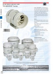
Installation / AdjustmentDescription of functions - Basic functionsGas boilerIn those cases, additional heating is supplied using a gasboiler you can choose to connect it as an oil boiler if youneed to control a shunt valve or alternatively connect it asan electric boiler.See the section Description of functions - Basic functions> Electrical additional heater to connect it as an electricboiler and the section Description of functions - Basicfunctions > Oil boiler to connect it as an oil boiler.HPACNOTE!This system solution means that the brinewill also circulate through the heatingsystem. Check that all component parts aredesigned for the brine in question.HPAC can either be connected to the Base card or to theExpansion card 11. When HPAC is to be connected to theBase card the immersion heater can be run at a maximumon one step.Control of cooling mode takes place by means of anoutdoor sensor and, when connected, a room sensor (RG10/RG 05, see the section Description of functions - Basicfunctions > Room control for a description of the connection).The control of cooling to the house takes place accordingto the set curve slope and curve offset in menus 6.4.2 and6.4.3. After adjustment, the house receives the correctamount of cooling for the prevailing outdoor temperature.The flow temperature from HPAC will fluctuate around thetheoretical required value (value in brackets in menu 2.0).In the event of excess temperature, <strong>F1330</strong> calculates asurplus in the form of degrees-minutes, which means thatthe connection of cooling production is accelerated thegreater the excess temperature that temporarily prevails.<strong>F1330</strong> automatically switches to cooling mode when theoutdoor temperature exceeds the set value in menu 6.4.5.Passive cooling means that <strong>F1330</strong>, with the help of the circulationpumps, circulates fluid from the soil/rock collectorin the house’s distribution system and cools the house.In the event of a large cooling requirement where passivecooling is not sufficient, active cooling is engaged at thelimit value set in menu 6.4.7. A compressor then starts andthe cooling produced circulates to the house’s distributionsystem and heat is circulated out to the soil/rock collector.When more compressors are available, these will start witha difference on the set degree-minute setting in menu6.4.8.Three different cooling curves can be selected,see the figure for a detailed description.Calculatedflow temperature°C2015 c=1 k=110500c=2 k=2c=3 k=3 OutdoorUtetemp. temperature20 3040 °CIf room sensors (RG 10/RG 05) are connected, coolingstarts at a 1 degree excess temperature in the room andthe supply calculation counts on an outdoor temperatureof 30 °C (if the outdoor temperature is greater, then theactual outdoor temperature is used). When the room temperaturehas fallen to 0.5 degrees of excess temperature,the cooling is switched off. To prevent self-oscillation in theheating system, there is a neutral zone between heatingand cooling operations.Lower shunt (SV-V2) is regulated during cooling operationin opposite direction to heating operation, which normallymeans the shunt closes completely during cooling operation.The outline diagram with docking instructions isavailable at www.nibe.com30 <strong>NIBE</strong> <strong>F1330</strong>
Installation / AdjustmentDescription of functions - Basic functionsConnection of HPACWhen HPAC Basec. is selected in menu 9.1.10:The shuttle valve for active cooling. (VXV-ACX) is connectedto the terminal block X6:19 (NC with activecooling mode, i. e. 230 V).The shuttle valve for passive cooling. (VXV-PCX) is connectedto terminal block X6:16 (NC with passive oractive cooling mode i. e. 230 V).The supply voltage for HPAC is connected to terminalblocks X6:14 (230 V) and X6:15 (N).When HPAC Expcard 11 is selected in menu 9.1.10:The shuttle valve for active cooling. (VXV-ACX) is connectedto X6A:23 (NC with active cooling mode, i. e. 230 V).The shuttle valve for passive cooling. (VXV-PCX) is connectedto terminal block X6:22 (NC with passive or activecooling mode i. e. 230 V).The supply voltage for HPAC is connected to terminalblocks X6:20 (230 V) and X6:21 (N).+Base cardX6X6aFor details how to connect a room sensor (RG 10/ RG 05)see the section, Description of functions - Basic functions >Room control.LEKThe heat pump in the picture is fitted with accessories.Quick guide - menu settings HPACMenu 9.1.10 Cooling[S]The type of cooling system is set here. The options availableare: Off, HPAC Basecard, HPAC Expcard 11 andCoolacc. The factory setting is Off.Menu 6.4.1 CoolingHere is cooling function can be set On or Off.The factory setting is Off.[U]Menu 6.4.2 Cooling curve[U]The selected curve slope (cooling curve) is shown here).The value is adjustable between 1 and 3.The factory setting is 2.Menu 6.4.3 Offset cold curveThe selected cooling curve offset is shown here.The value is adjustable between -10 and +10.The factory setting is 0.[U]Menu 6.4.4 Start temp. heating[U]Outdoor temperature (menu 4.0) at the outdoor sensor(UG) when the heat pump switches to heating mode.The value is adjustable between 0 and 30 °C.The factory setting is 20 °C.Menu 6.4.5 Start temp. cooling[U]Outdoor temperature (menu 4.0) on the outdoor sensor(UG) when the heat pump switches to cooling mode.The value is adjustable between 0 and 30 °C.The factory setting is 25 °C.Menu 6.4.6 Start active cooling[U]The heat pump starts to actively produce cooling at thisdegree-minute surplus. The value is adjustable between10 and 500 degree-minutes. The factory setting is 30degree-minutes.Menu 6.4.7 GM for compr.-stepDegree-minute difference between compressor stages.The value is adjustable between 10 and 500 degreeminutes.The factory setting is 30 degree-minutes.Menu 6.4.8 Diff PC/ACIf the flow temperature on the sensor (FG) exceeds thecalculated flow temperature + this value the systemswitches to active cooling. The value is adjustable between1 and 9 °C. The factory setting is 4 °C.9 °C.[U][U]<strong>NIBE</strong> <strong>F1330</strong>31
Installation / AdjustmentDescription of functions - Basic functionsFixed condensingWith fixed condensing the compressor start for heatcharging is regulated using the flow line sensor (FG). Thestart and stop temperatures can be set in the sub-menusto 2.7.0. The compressors and additional heating steps arestarted and stopped with a 0.5 degree minus difference.That is to say, if compressor 1 starts at 50 °C and stops at55 °C, compressor 2 starts at 49.5 °C and stops at 54.5 °Cetc.When the sub shunt (SV-V2) is required this can beconnected to the Expansion card 11, see the sectionDescription of functions - Expansion card 11 > Sub shunt.Connection of fixed condensingThe flow line sensor (FG) is ideally placed in a submergedtube in the working tank, boiler or the like.To connect the sub shunt (SV-V2) see the sectionDescription of functions - Expansion card 11 > Sub shunt.Quick guide - menu settingsfixed condensingMenu 9.1.7 Fixed condensingHere fixed condensing is set either On or Off.The factory setting is Off.Menu 2.7.1 Starttemp.compressor[S]Temperature on the flow line sensor (FG) when the firstcompressor starts. The value is adjustable between 5and 60 °C. The factory setting is 47 °C.Menu 2.7.2 Stoptemp. compressorTemperature on the flow line sensor (FG) when the lastcompressor stops. The value is adjustable between 5and 60 °C. The factory setting is 50 °C.Menu 2.7.3 Starttemp. additive[U][U][U]Temperature on the flow line sensor (FG) when additionalheating engages. The value is adjustable between5 and 60 °C. The factory setting is 45°C.Menu 2.7.4 Stoptemp. additiveTemperature on the flow line sensor (FG) when additionalheating disengages. The value is adjustable between5 and 60 °C. The factory setting is 49 °C.[U]Floor drying functionIn order to obtain the correct drying of new concretefloors, the integrated floor drying function can be used.The function forces the temperature on the flow line sensor(FG) to fixed temperatures irrespective of the outdoortemperature and curve settings.The settings for the function can be found in the submenusto 9.2.0.Once the selected program is complete, control of the flowtemperature automatically returns to normal operation.Quick guide - menu settingsfloor drying functionMenu 9.2.1 Op-mode floor dryingThe operating mode for the floor drying function is sethere. Selectable modes are:Off: Normal operation, i.e. the floor drying function isswitched off.[S]Own program: Two fixed temperatures in two periodsare adjustable in menu 9.2.3 to 9.2.6.Fixed program: The flow temperature starts day 0 at20 degrees and increases each day by 5 degrees. Thetemperature has reached 45 degrees on day 5, this ismaintained on days 6 and 7. The program is terminatedby lowering the temperature on days 8 to 12 by 5 degreeson each day.The factory setting is Off.Menu 9.2.2 Floor drying day[U]Here you can see which day the floor drying functionis on. It is also possible here to enter the floor dryingprogram by changing this value. The value is adjustablefrom 0 to 20 days. The factory setting is 0.Menu 9.2.3 Nos. of days per. 1[U]Here you set the number of days that the flow temperatureshall maintain the temperature in menu 9.2.4 whenOwn program in menu 9.2.1 is selected. The value isadjustable between 1 and 10 days. The factory settingis 5 days.Menu 9.2.4 Temperature per. 1[U]Here you set the temperature to be maintained on theflow line sensor (FG) during period 1 when Own programis selected in menu 9.2.1. The value is adjustablebetween 15 and 50 °C. The factory setting is 25 °C.Menu 9.2.5 Nos. of days per. 2[U]Here you set the number of days that the flow temperatureshall maintain the temperature in menu 9.2.6 whenOwn program in menu 9.2.1 is selected. The value isadjustable between 1 and 10 days. The factory settingis 5 days.The outline diagram with docking instructions isavailable at www.nibe.comMenu 9.2.6 Temperature per. 2[U]Here you set the temperature to be maintained on theflow line sensor (FG) during period 2 when Own programis selected in menu 9.2.1. The value is adjustablebetween 15 and 50 °C. The factory setting is 35 °C.32 <strong>NIBE</strong> <strong>F1330</strong>
Installation / AdjustmentDescription of functions - Basic functionsRoom controlA thermostat can be connected to temporarily change thecalculated flow temperature. It is also possible to connecta thermostat to the sub shunt system (see the sectionDescription of functions - Expansion card 11 > Sub shunt).When thermostat control is required, Thermostat shouldbe selected in the menu 9.1.11.Alternatively a room sensor of the type RG10 (accessory)can be connected to the system. This includes settings forthe required room temperature and the system automaticallycompensates the calculated flow temperature accordingto the difference between the true and required roomtemperature.Room sensors can be used together with the cooling functionson Expansion card 12. Cooling production starts at1 degree excess temperature in the room if, at the sametime, the mean outside temperature (menu 4.1) exceedsthe set temperature in menu 6.4.5 alternatively 6.8.6.Connection of room controlWhen Thermostat is selected in menu 9.1.11:Connect the thermostat for heating system 1 to thescrew terminals X1:12 and 13 on the EBV-card (RTGA)and, when required, the thermostat for heating system2 (Sub shunt) to the terminal blocks X1:14 and X1:15 onthe EBV-card (RTGB). The thermostat/s shall be potentialfree and normally open (NO).If RG10 is selected in menu 9.1.11:Connect screw terminal X1:12 to the screw terminal inRG10 marked 2.Connect screw terminal X1:13 to the screw terminal inRG10 marked 6.Connect screw terminal X1:14 to the screw terminal inRG10 marked 1.Om valt ”RG05” i meny 9.1.11:Connect X1:12-13.+EBV-cardX1LEKThe heat pump in the picture is fitted with accessories.Quick guide - menu settings room controlMenu 9.1.11 Room control modeHere the type of room control connected is set. Selectablemodes are Off, Thermostat, RG05 or RG10. The factorysetting is Off.If Thermostat is selected in menu 9.1.11:Menu 2.5 External adjustment[S][U]When the thermostat is selected in menu 9.1.11, you canconnect an external contact, see Electrical connection -External contacts. Using an external contact, for example,a room thermostat or a timer allows you to temporarily orperiodically raise or lower the flow temperature and withthat the room temperature. When the external contact ismade, the heating curve offset is changed by the numberof steps shown here. The value is adjustable between-10 and +10. The factory setting is 0.Even the menu 3.5 (External adjustment 2) comes intoquestion if the Sub shunt (SV-V2) has been activated.If RG10 or RG05 is selected in menu 9.1.11:Menu 6.9.1 Room balancing[U]Here you set the factor that determines how much deviationbetween the desired and true room temperaturesshall affect the flow temperature. The factor is adjustablebetween 0 and 6 in increments of 0.1. The factory settingis 1.0.Menu 6.9.2 Room balancingsystemHere you select which heating system the room sensorshall affect. Can be set to Off, Heating syst1, Heatingsyst2 or Heatingsys 1&2. The factory setting is Off.If RG10 or RG05 is selected in menu 9.1.11:Menu 6.9.3 Desired room temperature[U][U]The menu is only displayed if RG05 is selected in menu9.1.11. The value can be adjusted between 10 and 30 °Cin increments of 0.5 °C. Factory setting is 20 °C.<strong>NIBE</strong> <strong>F1330</strong>33
Installation / AdjustmentDescription of functions - Expansion card 11Description of functions - Expansion card 11NOTE!Access to the following functions requiresthe Expansion card 11 (10) accessory withassociated terminal block X6A.When this is connected the cardmust be activated in menu 9.1.1.X6aLEK10Electrical additional heaterTo connect the relays ETS-4 to ETS-6, see the sectionDescription of functions - Basic functions > Electricaladditional heater.HPACTo connect HPAC on Expansion card 11 see the sectionDescription of functions - Basic functions > HPAC.The heat pump in the picture is fitted with accessories.34 <strong>NIBE</strong> <strong>F1330</strong>
Installation / AdjustmentDescription of functions - Expansion card 11Hot water circulation pumpA hot water circulation pump (VVC) can be controlled tocirculate the hot water by operating time or period timewithin the selected time period.The Hot water circulation pump (Hw-cp) (VVC) connectioncan be made using a T-piece docking to an electricwater heater (peak water heater). This is done especiallyon smaller installations. The docking is independent ofhow the heat pump works with the double-jacketed waterheater.When connected to a separate Hw-cp (VVC) outlet on thedouble-shelled water heater (e.g. VPA) it is important thatthe circulation flow is accurately adjusted and that themixing valve on any electric peak water heater is not settoo high. This can result in the stratification in the doublejacket being disturbed and the heat pump knocked out.This docking is especially used on large installations, whiche.g. use two, double-jacketed water heaters. The sensor(VVG) is placed in the first water heater and the Hw-cp(VVC) connection is made to the other.X6aConnection of hot water circulation pumpThere is a potential free relay for the Hw-cp function,which can be used for the control voltage or power supply(max 16 A, 250 V). When the relay is used for the controlvoltage, you can strap the power supply from X6A:20to X6A:19, use X6A:21 as N and then get the signal onX6A:18. Max. current may then be 0.4 A and the controlvoltage becomes 230 V. If you take more output fromX6A:20 you can overload the L1-phase causing the fuseto trip.The supply to the control signal/power supply to the Hw-cp(VVC) is connected to the terminal block X6A:19 (Max fuse16 A and 250 V) and the control signal/power supply out ison terminal X6A:18.+Exp.card 11LEKQuick guide - menu settingshot water circulation pumpMenu 6.1.4 Time of period Hw-cp[U]Here you select between which times of the day the hotwater circulation pump shall run according to the periodtime (menu 6.1.5) and the operating time (menu 6.1.6).Menu 6.1.6 Operatingtime Hw-cp[U]The operating time per period for the hot water circulationpump is selected here. Adjustable between 1 and 60minutes. The factory setting is 3 minutes.Menu 6.1.5 Periodtime Hw-cp[U]Here the period time for the hot water circulation pumpis set here. Adjustable between 10 and 60 minutes. Thefactory setting is 15 minutes.The heat pump in the picture is fitted with accessories.The outline diagram with docking instructions isavailable at www.nibe.com<strong>NIBE</strong> <strong>F1330</strong>35
Installation / AdjustmentDescription of functions - Expansion card 11PoolA shuttle valve (VXV-P) can be connected to control onepart of, or the entire, heating medium flow to a poolexchanger. The shuttle valve, or, if required - the shuttlevalves (however, with the same control signal), is/areinstalled on the heating medium circuit that goes to theradiator system as normal. The compressor modules thatare connected via pool exchange valve must be selectedas available for pool operation in menu 5.4.12 and 5.4.13.Circulation pump VBP3 must be installed for pool operation.During pool heating, the heating medium circulates betweenthe heat pump and pool exchanger using the heatpump’s internal circulation pumps (VBP-A respectivelyVBP-B). VBP3 circulates the heating medium around theheating system and additional heat can be connected asrequired at the same time as the flow line sensor (FG) continuouslysenses the heating requirement of the house.Start and stop temperatures for pool heating are set inmenu 6.5.1 respectively 6.5.2. Heating operation is normallyprioritised before pool heating, but shifting betweenpool heating and heating operation can be set in menus6.5.3 and 6.5.4 if required. If the same value is set in boththe menus, heating operation is prioritised before poolheating.If several compressors are available for pool operation,these start at 5 minute intervals until no more are availableor the number of started compressors is the same as thenumber that is selected in menu 6.5.5.Connection of poolShuttle valves (VXV-P) is connected to the terminal blocksX6A:1 (230 V), X6A:2 (N) and X6A:3 (NC) or X6A:4 (NO).The pool temperature sensor (PTG) is either fitted on thecirculation pipe for the pool water (presupposes continuouscirculation) or in a submerged tube in the pool. The sensoris connected to screw terminals X1:3 and X1:4 on theEBV-card.+EBV-cardX1X6ALEKThe heat pump in the picture is fitted with accessories.36 <strong>NIBE</strong> <strong>F1330</strong>
Installation / AdjustmentDescription of functions - Expansion card 11Quick guide - menu settings poolMenu 9.1.5 PoolHere pool heating is set either On or Off. The factory settingis Off.Menu 6.5.1 Start temp. pool[S][U]Here you select at which pool temperature on the sensor(PTG) heating should start. The value is adjustable between5 and 60 °C in increments of 0.5 °C. The factorysetting is 22.0 °C.Menu 6.5.2 Stop temp. pool[U]Here you select at which pool temperature on the sensor(PTG) heating should stop. Adjustable between 5 and60 °C in increments of 0.5 °C. The factory settingis 24.0 °C.Menu 6.5.3 Periodtime heat/poolThe length of time is set here. The value is adjustablebetween 10 and 1000 minutes. The factory setting is100 minutes.Menu 6.5.4 Max-time heatproduct[U][U]Here you select how much time of the period time (menu6.5.3) is to be used to heat the house when there is aneed of heating and pool heating. The value is adjustablebetween 0 and 1000 minutes. The factory setting is 50minutes.Menu 6.5.5 Max compr. to pool[U]The maximum number of compressors that can be operatedtowards the pool exchanger (VX-P) is set here. Thenumber of compressors that currently produce pool heatis within brackets. The value can be adjusted between 0and 18. Factory setting is 1.Menu 5.4.12 Pool heating compr. AThe menu is only displayed when pool is selected as“On” in menu 9.1.5[U]If it is “On”, compr. A in the heat pump that is selectedin menu 5.1 is permitted to carry out pool heating.Menu 5.4.13 Pool heating compr. BThe menu is only displayed when pool is selected as“On” in menu 9.1.5If it is “On”, compr. B in the heat pump that is selectedin menu 5.1 is permitted to carry out pool heating.[U]The outline diagram with docking instructions isavailable at www.nibe.com<strong>NIBE</strong> <strong>F1330</strong>37
Installation / AdjustmentDescription of functions - Expansion card 11Sub shuntA shunt valve (SV-V2) and a circulation pump (VBP4) canbe connected to a second heating circuit with a lowertemperature requirement.The circulation pumps for heating circuits 1 and 2 (VBP3and VBP4) are controlled together. These are activated instandby mode.The flow temperature is controlled via the shunt valve’sincrease/decrease signal and the sensor FS2.The possibility to set the period and pulse times for theshunt are located in menus 3.8 and 3.9.The calculation of the flow temperature is done in thesame way and with the same type of settings as forheating circuit 1.Connection of the sub shuntThe flow line sensor 2 (FS2) is fitted on the flow line towardsheating circuit 2. The sensor must make good contactwith the measurement area to give the best function.When a submerged tube is not available, use the suppliedcopper tube. The sensor is connected to screw terminalsX4:7 and X4:8 on the EBV-card”.The return sensor 2 (RG2) is fitted on the flow line towardsheating circuit 2. The sensor must have good insulationand make good contact with the measurement area to givethe best function. The sensor is connected to screw terminalsX4:5 and X4:6 on the EBV-card”.The pump’s (VBP4) control signal is connected to the terminalblocks X6:19 (230 V), X6:20 (N), i. e. same connectionas VBP3.The shunt valve (SV-V2) is connected to the terminal blocksX6A:5 (230 V decrease signal), X6A:6 (N) and X6A:7(230 V increase signal).Note that <strong>F1330</strong> delivers 230 V control signals intendedto control external contactors and not to drivepumps.+EBV-cardX4X6X6AX4LEKThe heat pump in the picture is fitted with accessories.38 <strong>NIBE</strong> <strong>F1330</strong>
Installation / AdjustmentDescription of functions - Expansion card 11Quick guide - menu settings sub shuntMenu 9.1.4 Sub shuntHere the sub shunt is set either On or Off. The factorysetting is Off.Menu 3.1 Curve slope 2[S][N]The selected curve slope for the heating curve is shownhere. The value is adjustable between curve 1 and 15, orin position Own curve. The values for own curve are setin menu 3.6.0. The factory setting is 9.Menu 3.2 Offset heatingcurve 2[N]The chosen offset for the heating curve is shown here.The value is adjustable between -10 and +10. The factorysetting is 0.If the RCU is connected, the set offset is shown via RCUbetween brackets. The actual offset then becomes thetotal of the set offset and RCU offset.Menu 3.3 Min. flow temp. 2[U]The set minimum level for the flow temperature to theheating system is shown here. The calculated supply temperaturenever drops below this level irrespective of theoutdoor temperature, curve slope or offset heating curve.The value is adjustable between 10 and 65 °C.The factory setting is 15 °C.Menu 3.4 Max. flow temp. 2[U]The set maximum level for the supply temperature tothe heating system is shown here. The calculated supplytemperature never exceeds this level irrespective of theoutdoor temperature, curve slope or offset heating curve.The value is adjustable between 10 and 80 °C.The factory setting is 55 °C.Menu 3.8 Shunt period time[U]Here you select the period time, i. e. the time betweencorrections for the sub shunt (SV-V2). The value is adjustablebetween 10 and 500 seconds. The factory setting is120 seconds.Menu 3.9 Shunt intensificat.[U]Here you select how many seconds the sub shunt (SV-V2)shall run in relation to the difference between the calculatedflow and the true flow. For example, a difference of2 degrees and a set amplification of 5 gives 10 seconds incontrol of the sub shunt. The value is adjustable between1 and 10. The factory setting is 1.The outline diagram with docking instructions isavailable at www.nibe.com<strong>NIBE</strong> <strong>F1330</strong>39
Installation / AdjustmentDescription of functions – Expansion card 12Description of functions – Expansion card 12NOTE!The accessory ”Expansion card 12” (11)with accompanying terminal block X6B isrequired in order to access the followingfunctions. When it has been connected thecard must be activated in menu 9.1.2.X6bLEKDocking instructionsOutline diagrams with docking instructions for thefunctions on the expansion card 12 is at the addresswww.nibe.com11The heat pump in the picture is fitted with accessories.40 <strong>NIBE</strong> <strong>F1330</strong>
Installation / AdjustmentDescription of functions – Expansion card 12Groundwater pumpA ground water pump (CP-G) can be controlled by <strong>F1330</strong>.The pump starts 20 seconds before the first compressorstarts and stops 20 seconds after the last compressorstops.Ground water pump connectionThere is a potential free relay for the ground water pumpfunction (CP-G), which can be used as control voltage orpower supply (Max 6 A, 250 V).If the relay is used as control voltage, the supply can bebridged internally from X13:4 to X6B:24, use X13:9 as Nand receive the signal on X6B:25, but max current must be0.4 A and the control voltage is 230 V.The external supply to the control signal/power supply forthe ground water pump (CP-G) is connected to terminalblock X6B:24 (max fusing 6 A and 250 V) and the controlsignal/power supply is on X6B:25.X6b+Exp. card 12LEKX13The heat pump in the picture is fitted with accessories.The outline diagram with docking instructions isavailable at www.nibe.com<strong>NIBE</strong> <strong>F1330</strong>41
Installation / AdjustmentDescription of functions – Expansion card 12Passive cooling with 4 pipe systemThe cooling system is connected to the heat pump collectorcircuit, through which cooling is supplied from the collectorvia the circulation pump (CP-K) and the shunt valve(SV-K).When cooling is required (activated from the outdoorsensor and any room sensor) the three way valve and thecirculation pump are activated. The shunt valve regulatesso that the cooling sensor (KG) reaches the current setpoint value that is equal to the outdoor temperature andthe set min. value for the cooling temperature (to preventcondensation).For connection of, and function for, room sensors, see section“Description of functions – Basic functions” > “Roomcontrol”.X6bConnection of passive cooling with 4 pipe systemThe shunt valve (SV-K) is connected to terminal blockX6B:9 (230 V reduce signal), X6B:8 (N) and X6B:10 (230 Vincrease signal).There is a potential free relay for the circulation pump function(CP-K), which can be used as control voltage or powersupply (Max 6 A, 250 V). If the relay is used as controlvoltage the supply can be bridged internally from X13:4to X6B:22, use X13:9 as N and then receive the signal onX6B:23. Max current must be 0.4 A and the control voltageis 230 V.External supply to the control signal/power supply for thecirculation pump (CP-K) is connected to terminal blockX6B:22 (max fusing 6 A and 250 V) and the control signal/power supply is on X6B:23.For the cooling sensor (KG) location see docking instructions.The sensors must have a good contact with themeasuring point for best function. If a submerged tube isnot available, use the copper tube supplied.The sensor is connected to screw terminals J5:7 and J5:8on the “measurement card”.J5LEKX13+Measure card+Exp. card 12The heat pump in the picture is fitted with accessories.42 <strong>NIBE</strong> <strong>F1330</strong>
Installation / AdjustmentDescription of functions – Expansion card 12Quick guide – menu settingsfor passive cooling with 4 pipe systemMenu 9.1.10 Cooling[S]The type of cooling system is set here. The selectablemodes are: ”Off”, ”HPAC base card”, ”HPAC expansioncard 11”, ”Cooling accumulator”, “PKM 2 pipes” and“PKM 4 pipes”. The factory setting is “Off”.Select “PKM 4 pipes”.Menu 6.4.1 Cooling[U]The cooling functions can be set to “On” or “Off” here.The factory setting is “Off”.Menu 6.4.2 Cooling curve[U]The selected curve slope (cooling curve) is shown here.The value can be set between 1 and 3. The factory settingis 2.Menu 6.4.3 Offset cold curve[U]The selected cooling curve offset is shown here. The valuecan be set between -10 and +10. The factory setting is 0.Menu 6.4.4 Start temp. heating[U]Outdoor temperature (menu 4.0) at the outdoor sensor(UG) when the heat pump is permitted to produce heat.The value can be set between 0 and 30 °C. The factorysetting is 20 °C.Menu 6.4.5 Start temp. cooling[U]Outdoor temperature (menu 4.0) at the outdoor sensor(UG) when the heat pump is permitted to produce cooling.The value can be set between 0 and 30 °C.The factory setting is 25 °C.Menu 6.4.9 Min. flow temp.The lowest flow temperature in cooling mode.The value is adjustable between 2 and 65 °C.The factory setting is 5 °C.Menu 6.4.10 Period time shuntThe time period for the shunt (SV-K) is chosen here.Adjustable between 1 and 500 seconds.The factory setting is 60 seconds.Menu 6.4.11 Shunt intensification.[U][U][U]The amplification for the shunt (SV-K) is chosen here. Forexample, a 2 degree difference between the flow lineand the calculated flow line with 5 in amplification gives10 secs/min controlling the shunt. The value can be setbetween 1 and 10. The factory setting is 1.The outline diagram with docking instructions isavailable at www.nibe.com<strong>NIBE</strong> <strong>F1330</strong>43
Installation / AdjustmentDescription of functions – Expansion card 12Passive cooling with 2 pipe systemThe collector circuit is connected to a heat exchanger via athree way valve (VXV-KV A/B). The other side of the exchangeris connected to the heating medium circuit via ashunt valve (SV-K) and a circukation pump (PC-K).When cooling is required (activated from the outdoorsensor and any room sensor) the three way valve and thecirculation pump are activated. The shunt valve regulatesso that the cooling sensor (KG) reaches the current setpoint value that is equal to the outdoor temperature andthe set min. value for the cooling temperature (to preventcondensation).For connection of, and function for, room sensors, see section“Description of functions – Basic functions” > “Roomcontrol”.X6bConnection of passive cooling with 2 pipe systemThree way valve (VXV-KV A/B) is connected to terminalblock X6B:1 (230 V), X6B:2 (N) and X6B:3 (NC) alternativelyX6B:4 (NO).The shunt valve (SV-K) is connected to terminal blockX6B:8 (230 V reduce signal), X6B:9 (N) and X6B:10 (230 Vincrease signal).There is a potential free relay for the circulation pump function(CP-K), which can be used as control voltage or powersupply (Max 6 A, 250 V). If the relay is used as controlvoltage the supply can be bridged internally from X13:4to X6B:22, use X13:9 as N and then receive the signal onX6B:23. Max current must be 0.4 A and the control voltageis 230 V.External supply to the control signal/power supply for thecirculation pump (CP-K) is connected to terminal blockX6B:22 (max fusing 6 A and 250 V) and the control signal/power supply is on X6B:23.LEKX13+Exp. card 2The heat pump in the picture is fitted with accessories.44 <strong>NIBE</strong> <strong>F1330</strong>
Installation / AdjustmentDescription of functions – Expansion card 12Quick guide – menu settingsfor passive cooling with 2 pipe systemMenu 9.1.10 Cooling[S]The type of cooling system is set here. The selectablemodes are: ”Off”, ”HPAC base card”, ”HPAC expansioncard 11”, ”Cooling accumulator”, “PKM 2 pipes” and“PKM 4 pipes”. The factory setting is “Off”.Select “PKM 2 pipes”.Menu 6.4.1 Cooling[U]The cooling functions can be set to “On” or “Off” here.The factory setting is “Off”.Menu 6.4.2 Cooling curveThe selected curve slope (cooling curve) is shown here.The value can be set between 1 and 3.The factory setting is 2.Menu 6.4.3 Offset cold curve[U][U]The selected cooling curve offset is shown here. The valuecan be set between -10 and +10. The factory setting is 0.Menu 6.4.4 Start temp. heating[U]Outdoor temperature (menu 4.0) at the outdoor sensor(UG) when the heat pump is permitted to produce heat.The value can be set between 0 and 30 °C.The factory setting is 20 °C.Menu 6.4.9 Min. flow temp.The lowest flow temperature in cooling mode.The value is adjustable between 2 and 65 °C.The factory setting is 5 °C.Menu 6.4.10 Period time shuntThe time period for the shunt (SV-K) is chosen here.Adjustable between 1 and 500 seconds.The factory setting is 60 seconds.Menu 6.4.11 Shunt intensification.[U][U][U]The amplification for the shunt (SV-K) is chosen here. Forexample, a 2 degree difference between the flow lineand the calculated flow line with 5 in amplification gives10 secs/min controlling the shunt. The value can be setbetween 1 and 10. The factory setting is 1.Menu 6.4.12 Time betw. heat cold[U]The time the heat pump must wait between productionof heat and cooling is set here. The value can be set between0 and 10 hours. The factory setting is 3 hours.Menu 6.4.5 Start temp. cooling[U]Outdoor temperature (menu 4.0) at the outdoor sensor(UG) when the heat pump is permitted to produce cooling.The value can be set between 0 and 30 °C.he factory setting is 25 °C.The outline diagram with docking instructions isavailable at www.nibe.com<strong>NIBE</strong> <strong>F1330</strong>45
Installation / AdjustmentDescription of functions – Expansion card 12Combined cooling/heating modes with accumulatorsThe installation consists of one or more <strong>F1330</strong>s with accumulatortanks on both the collector and heat mediumsides. Ground/rock collector(s) have three way valves sothat the accumulator tanks can be utilised as:1. Heat storage in heating mode2. Cold storage in passive cooling mode3. Heat dump in active cooling modeHeat production occurs via the accumulator tank wherethe flow line sensor (FG) is located.The circulation pump (VBP3) circulates the heating mediumfrom the tank to the distribution system.The brine circulates between the brine tank and the heatpump evaporator. When the temperature is lowered in thetank (small cooling requirement in the system) the circulationpump (CP-KO) is started to retrieve energy from thecollector.When the cooling sensor (KG) requests cooling, the circulationpump (CP-K) starts and the shunt valve (SV-K) startsregulating cooling from the brine tank. In the event of fallingtemperatures in the tank (KBack) CP-KO is started toretrieve cooling from the collector (passive cooling). Whenthe collector is unable to provide sufficient cooling theheat pump is started to produce active cooling.In the event of excess heat, this is dumped to the collectoror outdoor air via a fan battery outdoors.J4J5X6bConnecting cooling/heating modes with accumulatorsNOTE! When dumping the excess heat in the outdoor air,the circulation pumps for dumping (CP-D) must be connectedin parallel. The fans in the outdoor air module canalso be connected with CP-D. VXV-KV A/B must not beused.Three way valve (VXV-KV A/B) is connected to terminalblock X6B:1 (230 V), X6B:2 (N) and X6B:3 (NC) alternativelyX6B:4 (NO).The control valve (SV-VVX) is connected to terminal blockX6B:9 (230 V reduce signal), X6B:8 (N) and X6B:10 (230 Vincrease signal).There are three potential free relays for functions CP-D, CP-KO & CP-K, which can be used as control voltage or powersupply (Max 6 A, 250 V). If the relay is used as controlvoltage the supply can be bridged internally from X13:4to X6B:18, , X6B:20 and X6B:22 and use X13:9 as N andreceive the control signal for CP-D on X6B:19, CP-KO onX6B:21 and CP-K on X6B:23. When connected like this themax current must be 1 A from X13:4 and the control voltageis 230 V.External supply to the control signal/power supply for CP-Dis connected to terminal block X6B:18 (max fusing 6 A and250 V) and the control signal/power supply is on X6B:19.External supply to the control signal/power supply for CP-KO is connected to terminal block X6B:20 (max fusing 6A and 250 V) and the control signal/power supply is onX6B:21.External supply to the control signal/power supply for CP-Kis connected to terminal block X6B:22 (max fusing 6 A and250 V) and the control signal/power supply is on X6B:23.The sensors must have a good contact with the measuringpoint for best function. If a submerged tube is not available,use the copper tube supplied.For the cooling sensor (KG) location see docking instructions.The sensor is connected to screw terminals J5:7 andJ5:8 on the “measurement card”.For the sensor KB-KO location see docking instructions.The sensor is connected to screw terminals J4:21 and J4:22on the “measurement card”.For the cooling sensor (KBack) location see docking instructions.If a submerged tube is not available, use the coppertube supplied. The sensor is connected to screw terminalsJ4:23 and J4:24 on the “measurement card”.LEKX13The heat pump in the picture is fitted with accessories.The outline diagram with docking instructions isavailable at www.nibe.com46 <strong>NIBE</strong> <strong>F1330</strong>
Installation / AdjustmentDescription of functions – Expansion card 12+Exp. card 2J4+Measure card+Measure cardQuick guide – menu settingscooling/heating modes with accumulatorsMenu 9.1.10 Cooling[S]The type of cooling system is set here. The selectablemodes are: ”Off”, ”HPAC base card”, ”HPAC expansioncard 11”, ”Cooling accumulator”, “PKM 2 pipes” and“PKM 4 pipes”. The factory setting is “Off”.Select “Cooling accumulator”.Menu 6.8.1 Cool acc temperatureShows the current temperature at the coolingaccumulator sensor (KBack).Menu 6.8.3 Cooling curve[N][U]The selected curve slope (cooling curve) is shown here.The value can be set between 1 and 3. The factory settingis 2.Menu 6.8.4 Offset cooling curve[U]The selected cooling curve offset is shown here. The valuecan be set between -10 and +10. The factory setting is 0.Menu 6.8.5 Start temp. heating[U]Outdoor temperature (menu 4.0) at the outdoor sensor(UG) when the heat pump is permitted to produce heat.The value can be set between 0 and 30 °C. The factorysetting is 20 °C.Menu 6.8.6 Start temp. cooling[U]Outdoor temperature (menu 4.0) at the outdoor sensor(UG) when the heat pump is permitted to produce cooling.The value can be set between 0 and 30 °C.The factory setting is 25 °C.Menu 6.8.7 Temp. to cool. acc.The desired temperature for the cooling accumulator isset here. The value can be set between 0 and 20 °C.The factory setting is 13 °C.Menu 6.8.9 Min. flow temp.The lowest flow temperature in cooling mode.The value is adjustable between 2 and 65 °C.The factory setting is 5 °C.Menu 6.8.10 Period time shuntThe time period for the shunt (SV-K) is chosen here.Adjustable between 1 and 500 seconds.The factory setting is 60 seconds.Menu 6.8.11 Shunt intensification.[U][U][U][U]The amplification for the shunt (SV-K) is chosen here.For example, a 2 degree difference between the flow lineand the calculated flow line with 5 in amplification gives10 secs/min controlling the shunt. The value can be setbetween 1 and 10. The factory setting is 1.<strong>NIBE</strong> <strong>F1330</strong>47
Installation / AdjustmentDescription of functions - External controlDescription of functions - External controlElectrical connection, external control/blockingof the additional heat and compressor2X1LEK22F 1330 can be controlled up to a certain pointusing signals from an external system (e.g. DUC).All control signals must come from potential free relays.Activating/blocking compressor A (KPRAA)When the input (KPRAA) is made, the compressor will stopirrespective of the operating status and the operating type.When the operating type is set to External control in menu0.2.x, the compressor A will start with an open input andstop when the input is made. However, alarms and timeconditions in <strong>F1330</strong> are superordinate to the external control.+EBV-cardConnection is made to terminals X4:1 and X4:2 on theEBV-card (2).Activating/blocking compressor B (KPRAB)Same function as above, but for compressor module B.Connection is made to terminals J5:1 and J5:2 on theMeasure card (22).+Measure cardJ5X4External Extra hot water activation (XVVA)If the input (XVVA) is made for at least one second, Extrahot water will be activated for 12 hours. See Descriptionof functions - Basic functions > Extra hot water for moreinformation.Connection is made to terminals X4:3 and X4:4 on theEBV-card (2).Tariff A (TA)Input (TA) can be used to select additional heat type (oilor electricity) if additional heat in menu 9.1.8 is selectedas ”El/Oil”. See ”Functions description- Basic functions” >”Electrical addition” and ”Function description- Basic functions”> ”Oil addition” for further descriptions.Connection is made to terminals X1:5 and X1:7 on theEBV-card (2).Tariff B (TB)When the input (TB) is made all electrical additional heatingis stopped. See Description of functions - Basic functions >Electrical additional heater for further details. Connection ismade to terminals X1:6 and X1:7 on the EBV-card (2).+EBV-cardThe heat pump in the picture is fitted with accessories.48 <strong>NIBE</strong> <strong>F1330</strong>
ControlControlControlGeneralThe menu tree shows all the menus. Three different menutypes can be chosen.SymbolsValue of the currentparameter[N]Normal, the menus the user needs for a quick productioncontrol.A BA BI II[U] Extended, shows all menus except the service menus.[S] Service, shows all menus. Returns to the previouslyselected menutype 30 minutes after the last buttonwas pushed.Changing of menu type is done from menu 8.1.1Information is provided on the display about the heatpump’s operating status. A screen saver is normally shownon the display screen. The plus and minus buttons and theenter button can be used to scroll through the menu systemas well as to change the set value in some menus.The plus button is used to move forward to thenext menu on the current menu level and to increasethe value of the parameter in menus wherethis is possible.The minus button is used to move back to theprevious menu on the current menu level and todecrease value of the parameter in menus wherethis is possible.The enter button is used to select sub-menus ofthe current menu, to permit parameters to bechanged and confirm any changes to parameters.When the menu number ends with “0” this indicatesthere is a sub-menu.Screen saverIn screen saver mode, you can see any alarms as well asthe flow temperatures currently given by the compressors(VBFA and VBFB) and whether the heat pump is a Masteror Slave. The screen saver is deactivated by pressingthe enter button and the button in the lower left forapproximately 8 seconds. Menu 1.0 is then displayed.The screen saver comes on automatically 30 minutes afterthe last button was pressed and when starting the heatpump.Exemple:5 4 , 1 5 5 , 7 ° CS l av e 35 0 . 0 ° CVa r m v a t t e n t e m p e r a t u r1.0 P 13.43Menu numberMenu namealt.Key lockH P - A L A R MS l av e 3ClockQuick movementTo quickly return to the main menu from sub-menus pressthe following: Operating mode button Enter buttonNOTE!Ensure the operating mode is not changedduring quick movement.Key lockA key lock can be activated in the main menus by simultaneouslypressing the plus and the minus buttons. The keysymbol will then be shown on the display. The same procedureis used to deactivate the key lock.<strong>NIBE</strong> <strong>F1330</strong>49
ControlControlChanging a parameterChanging a parameter (value): Access the required menu. Press the enter button, the numerical value starts toflash Increase or decrease the value using the plus respectiveminus button. Confirm by pressing the enter button. Menu 1.0 is automatically displayed again 30 minutesafter pressing the last button.ExampleChanging the Menu type, menu 8.1.1. The starting point is menu 1.0. Press the plus or minus button several times until menu8.0 is shown. Press the enter button to move to menu 8.1.0 Press the enter button to move to menu 8.1.1 Press the enter button to allow the value to bechanged. The value now starts to flash. Change the value usingthe plus or minus buttons. Confirm the selected value by pressing the enter button,the value will then stop flashing. Press the minus button to move to menu 8.1.5 Press the enter button to return to menu 8.1.0 Press the plus button 3 times to move to menu 8.4 Press the enter button to return to menu 8.0 Press the plus or minus button several times to move tomenu 1.08.0 Other settings [N]8.1.0 Display settings [N] 8.1.1 Menu type [N]8.2.08.1.2 Language [N]8.1.3 Display contrast [N]8.1.4 Light intensity [N]8.1.5 Return to 8.1.0 [N]Operatingmodesetting [U] 8.2.1 Only additional heat [U]8.2.2 Changing temperature [U]8.2.3 Start value compr. [U]8.2.4 GM for compr.step [U]8.2.5 Additive start value [U]8.2.6 GM for additive step [U]8.2.7 Flow diff HP [U]8.2.8 Diff HP-Add [U]8.2.9 Return to 8.2.0 [U]8.3.0 Load monitor [U] 8.3.1 Fuse size [U]8.4 Return to 8.0 [N]8.3.2 Max electric power [U]8.3.3 Current phase 1 [U]8.3.4 Current phase 2 [U]8.3.5 Current phase 3 [U]8.3.6 Ratio of transf. EBV [U]8.3.7 Tariff status [U]8.3.8 Return to 8.3.0 [U][N][U][S]Normal menus: Displayed in all menu modes.Extended menus: Only displayed when extended orservice is selected in menu 8.1.1.Service menus: Only dispalyed when service is selectedin menu 8.1.150 <strong>NIBE</strong> <strong>F1330</strong>
ControlControlMenu tree0.0 System [N]0.1.0 Status [N] 0.1.1 Status Master:A [N]0.1.2 Status Master:B [N]0.1.3 Status Slave 1:A* [N]0.1.4 Status Slave 1:B* [N]0.1.5 Status Slave 2:A* [N]0.1.6 Status Slave 2:B* [N]0.1.7 Status Slave 3:A* [N]0.1.8 Status Slave 3:B* [N]0.1.9 Status Slave 4:A* [N]0.1.10 Status Slave 4:B* [N]0.1.11 Status Slave 5:A* [N]0.1.12 Status Slave 5:B* [N]0.1.13 Status Slave 6:A* [N]0.1.14 Status Slave 6:B* [N]0.1.15 Status Slave 7:A* [N]0.1.16 Status Slave 7:B* [N]0.1.17 Status Slave 8:A* [N]0.1.18 Status Slave 8:B* [N]0.1.19 Return to 0.1.0 [N]0.2.0 Oper.type setting [S] 0.2.1 Oper. type Master [S]0.3 Return to 0.0 [N]0.2.2 Oper. type Slave 1 [S]0.2.3 Oper. type Slave 2 [S]0.2.4 Oper. type Slave 3 [S]0.2.5 Oper. type Slave 4 [S]0.2.6 Oper. type Slave 5 [S]0.2.7 Oper. type Slave 6 [S]0.2.8 Oper. type Slave 7 [S]0.2.9 Oper. type Slave 8 [S]0.2.10 Return to 0.2.0 [S]* Slaves 1-8 are only shown when made operational in menu 0.2.x1.0 Hotwater temp. [N]1.1 Start temperature HW [U]1.2 Stop temperature HW [U]1.3 Stop temp. compr XHW [U]1.4 Stop temperature XHW [U]1.5 Interval per. XHW [U]1.6 Periodtime HW/Heat. [U]1.7 Maxtime HW-product. [U]1.8 Diff between compr. [U]1.9.0HW with additionalheat [U] 1.9.11.9.2Start temp. additionalheatStop temp. additionalheat[U][U]2.0 Flow temperature [N]2.1 Curve slope [N]2.2 Offset heating curve [N]2.3 Min. flow temp. [U]2.4 Max. flow temp. [U]2.5 External adjustment [U]2.6.0Own curvedefinition [U] 2.6.1 Flow temp.at -20°C [U]2.6.2 Flow temp.at +20°C [U]2.6.3 Set buckling Temp. [U]2.6.4 Flowtemp.at buckling [U]2.6.5 Return to 2.6.0 [U]2.7.0 Fixed condensing [U] 2.7.1 Start temp.compressor [U]2.8 Return temperature [N]2.9 Degree minutes [N]2.10 Return to 2.0 [N]3.0 Flow temperature 2* [N]3.1 Curve slope 2 [N]3.2 Offset heatingcurve 2 [N]3.3 Min. flow temp. 2 [U]3.4 Max. flow temp. 2 [U]3.5 External adjustment2 [U]2.7.2 Stoptemp. compressor [U]2.7.3 Starttemp. additive [U]2.7.4 Stoptemp. additive [U]2.7.5 Return to 2.7.0 [U]3.6.0 Own curve definit.2 [U] 3.6.1 Flow temp.at -20°C [U]3.7 Return temperature 2 [N]3.8 Shunt period time 2 [U]3.9 Shunt intensificat. 2 [U]3.10 Return to 3.0 [N]* Accessories4.0 Outdoor temp. [N]4.1 Medium outdoor temp. [N]4.2 Return to 4.0 [N]3.6.2 Flow temp.at +20°C [U]3.6.3 Set buckling Temp. [U]3.6.4 Flowtemp.at buckling [U]3.6.5 Return to 3.6.0 [U]1.9.3 Return to 1.9.0 [N]1.10 Return to 1.0 [N]<strong>NIBE</strong> <strong>F1330</strong>51
ControlControl5.0 Heat pump [N]5.1 Heat pump unit [N]5.2.0 Compressor module A [N] 5.2.1 Heating flow/return [N]5.2.2 Brine in/out [N]5.2.3 Hot gas temperature [U]5.2.4 Overheating temp. [U]5.2.5 Liquide line temp. [U]5.2.6 Tot. starts compr. A [U]5.2.7 Opera.time compr. A [U]5.2.8 Return to 5.2.0 [N]5.3.0 Compressor module B [N] 5.3.1 Heating flow/return [N]5.3.2 Brine in/out [N]5.3.3 Hot gas temperature [U]5.3.4 Overheating temp. [U]5.3.5 Liquide line temp. [U]5.3.6 Tot. starts compr. B [U]5.3.7 Opera.time compr. B [U]5.3.8 Return to 5.3.0 [N]5.4.0 Settings [U] 5.4.1 Max.heat returntemp. [U]5.4.2 Min brine out [U]5.4.3 Max brine in [U]5.4.4 Level monitor [U]5.4.5 Start to start time [U]5.4.6 Oper. mode brinepump [U]5.4.7 Oper.mode heatpump A [U]5.4.8 Oper.mode heatpump B [U]5.4.9 Quickstart of compr. [U]5.4.10 Factory pre-set [U]5.4.11 Reset alarm [U]5.4.12 Pool heat comp A [U]5.4.13 Pool heat comp B [U]5.4.14 Return to 5.4.0 [N]5.5.0 Sensor calibration [S] 5.5.1 Heating return A [S]5.6 Return to 5.0 [N][N][U][S]5.5.2 Heating return B [S]5.5.3 Brine in [S]5.5.4 Brine out A [S]5.5.5 Brine out B [S]5.5.6 Outdoor temp.sensor [S]5.5.7 Room temp. sensor [S]5.5.8 Flow temp. sensor 1 [S]5.5.9 Flow temp. sensor 2 [S]5.5.10 Return to 5.5.0 [S]Normal menus: Displayed in all menu modes.Extended menus: Only displayed when extended orservice is selected in menu 8.1.1.Service menus: Only dispalyed when service is selectedin menu 8.1.16.0 External units* [N]6.1.0 Circulation pumps [U] 6.1.1 Op-mode external cp [U]6.2.06.1.2 Periodtime economy [U]6.1.3 Operati-time economy [U]6.1.4 Time of period Hw-cp [U]6.1.5 Periodtime Hw-cp [U]6.1.6 Operatingtime Hw-cp [U]6.1.7 Return to 6.1.0 [U]Immersionheatersettings [N] 6.2.1 Immersionheater type [U]6.2.2 Immersionheatrelays [U]6.2.3 Steps at 2h delay [U]6.2.4 Quickstart el.heater [U]6.2.5 Time factor el.cass. [U]6.2.6 Return to 6.2.0 [U]6.3.0 Boiler settings [N] 6.3.1 Oil boiler time [U]6.3.2 Start temp. shunt [U]6.3.3 Period time shunt [U]6.3.4 Shuntintensification [U]6.3.5 Timefactor oilboiler [U]6.3.6 Return to 6.3.0 [U]6.4.0 HPAC/PKM settings [U] 6.4.1 Cooling [U]6.4.2 Cooling curve [U]6.4.3 Offset cold curve [U]6.4.4 Starttemp. heating [U]6.4.5 Starttemp. cooling [U]6.4.6 Start active cooling [U]6.4.7 GM for compr.-step [U]6.4.8 Diff Passive/Active [U]6.4.9 Min. flow temp. [U]6.4.10 Periodtime shunt [U]6.4.11 Shunt intensificat [U]6.4.12 Time betw. heat cold [U]6.4.13 Return to 6.4.0 [U]6.5.0 Pool settings [N] 6.5.1 Start temp. pool [U]6.5.2 Stop temp. pool [U]6.5.3 Periodtime heat/pool [U]6.5.4 Max-time heatproduct [U]6.5.5 Max compr. to pool [U]6.5.6 Return to 6.5.0 [U]6.6.0 HW storage vessel [N] 6.6.1 Loading temperature [U]6.6.2 Per.-time ctrl.valve [U]6.6.3 Ctrl.valve intensific. [U]6.6.4 Zero [U]6.6.5 Return to 6.6.0 [U]6.7.0 Collector [N] 6.7.1 Load collector temp. [N]6.7.2 Soil sensor temp. [N]6.7.3 Mindiff for collect. [U]52 <strong>NIBE</strong> <strong>F1330</strong>
ControlControl6.0 External units* [N]6.7.4 Maxdiff for collect. [U]6.7.5 Contload bripu col/e [U]6.7.6 Load collector only [U]6.7.7 Return to 6.7.0 [N]6.8.0 Cooling settings [N] 6.8.1 Cool acc temperature [N]6.8.2 Brine collector [N]6.8.3 Cooling curve [U]6.8.4 Offset cooling curve [U]6.8.5 Start temp. heating [U]6.8.6 Start temp. cooling [U]6.8.7 Temp. to cool. acc. [U]6.8.8 Cooldiff for acc. [U]6.8.9 Min. flow temp. [U]6.8.10 Periodtime shunt [U]6.8.11 Shunt intensificat. [U]6.8.12 Return to 6.8.0 [N]6.9.0 Room sensor [N] 6.9.1 Room balancing [U]6.9.2 Room balancingsystem [U]6.9.3 Desired room temp [U]6.9.4 Return to 6.9.0 [U]6.10 Return to 6.0 [N]* Accessories8.0 Other settings [N]8.1.0 Display settings [N] 8.1.1 Menu type [N]8.1.2 Language [N]8.1.3 Display contrast [N]8.1.4 Light intensity [N]8.1.5 Return to 8.1.0 [N]8.2.0 Operatingmodesetting [U] 8.2.1 Only additional heat [U]8.2.2 Changing temperature [U]8.2.3 Start value compr. [U]8.2.4 GM for compr.step [U]8.2.5 Additive start value [U]8.2.6 GM for additive step [U]8.2.7 Flow diff HP [U]8.2.8 Diff HP-Add [U]8.2.9 Return to 8.2.0 [U]8.3.0 Load monitor [U] 8.3.1 Fuse size [U]8.3.2 Max electric power [U]8.3.3 Current phase 1 [U]8.3.4 Current phase 2 [U]8.3.5 Current phase 3 [U]8.3.6 Ratio of transf. EBV [U]8.3.7 Tariff status [U]8.3.8 Return to 8.3.0 [U]8.4 Return to 8.0 [N]7.0 Clock [N]7.1 Date [N]7.2 Time [N]7.3.0 Temp set back time 1 [N] 7.3.1 Temp set back time 1 [U]7.3.2 Offset heating curve [U]7.3.3 - Set time Monday - [U]- 7.3.9 - Sunday [U]7.3.10 Return to 7.3.0 [U]7.4.0 Temp set back time 2 [U] 7.4.1 Temp set back time 2 [U]7.4.2 Offset heating curve [U]7.4.3 - Set time Monday - [U]- 7.4.9 - Sunday [U]7.4.10 Return to 7.4.0 [U]7.5.0 Timer Extra Hotwater [U] 7.5.1 Timer Extra Hotwater [U]7.5.2 - Extra HW Monday - [U]- 7.5.8 - Sunday [U]7.5.9 Return to 7.5.0 [U]7.6 Return to 7.0 [N]<strong>NIBE</strong> <strong>F1330</strong>53
ControlControl9.0 Service menues [N]9.1.0 System settings [S] 9.1.1 Expansion card 11 [S]9.1.2 Expansion card 12 [S]9.1.3 RCU [S]9.1.4 Sub shunt [S]9.1.5 Pool [S]9.1.6 Hot water acc. tank [S]9.1.7 Fixed condensing [S]9.1.8 Additive [S]9.1.9 Extra collector [S]9.1.10 Cooling [S]9.1.11 Room control mode [S]9.1.12 HW with additional heat [S]9.1.13 Return to 9.1.0 [S]9.2.0 Floor drying setting [S] 9.2.1 Op-mode floor drying [S]9.2.2 Floor drying day [S]9.2.3 Nos. of days per. 1 [S]9.2.4 Temperature per. 1 [S]9.2.5 Nos. of days per. 2 [S]9.2.6 Temperature per. 2 [S]9.3.0 Alarm log [S]9.2.7 Reteurn to 9.2.0 [S]9.3.1.0- 9.3.6.0 Alarm 1 - 6 [S] 9.3.x.1 Type of alarm [S]9.3.x.2 Heat pump [S]9.3.x.3 Date [S]9.3.x.4 Time [S]9.3.x.5 Outdoor temperature [S]9.3.x.6Hot watertemperature [S]9.3.x.7 Flow temperature. [S]9.3.x.8 Heating flow/return [S]9.3.x.9 Brine in/out [S]9.3.x.10 Hot gas temperature9.3.x.11 Overheating temp.9.3.x.12 Liquide line temp.9.3.x.13 Relay status 1 - 89.3.x.14 Relay status 9 - 149.3.x.15 Compressor status[S][S][S][S][S][S]9.3.7 Clear the alarm log [S]9.3.8 Return to 9.3.0 [S]9.3.x.16 Return to 9.3.x.0[S]9.4.0 Testing mode [S] 9.4.1 Force control [S]9.4.2 Relay card [S]9.4.3 Relay 1 - 8 [S]9.4.4 Relay 9 - 14 [S]9.4.5 Return to 9.4.0 [S]9.5 Return to 9.0 [S][N][U][S]Normal menus: Displayed in all menu modes.Extended menus: Only displayed when extended orservice is selected in menu 8.1.1.Service menus: Only dispalyed when service is selectedin menu 8.1.154 <strong>NIBE</strong> <strong>F1330</strong>
ControlControlMain menus[N]S y s t e m0 . 0[N]H e a t p u m p5 . 0Menu 0.0 SystemHere the current status of the various heat pump modulesare shown and settings concerning Master or Slave canalso be made.Menu 5.0 Heat pumpValues can be read and various settings can be madeconcerning each connected heat pump from these submenus.[N]5 4 . 1 ° CH o t w a t e r t e m p e r a t u r e1 . 0[N]E x t e r n a l u n i t s6 . 0Menu 1.0 Hotwater temperatureThe current water temperature (VVG) is shown here.Menu 6.0 External unitsValues can be read and various settings can be made fromthese sub-menus. Many of the sub-menus to 6.0 requireaccessories.[N]3 1 . 7 ( 2 8 . 0 ) ° CF l o w t e m p e r a t u r e2 . 0[N]C l o c k7 . 0Menu 2.0 Flow temperatureThe current flow temperature (FG) for the heating systemis shown here with the calculated flow temperature inbrackets.Menu 7.0 ClockSettings regarding the date and time are made in thesub-menus of this menu. Even different temperature reductionsand increases at selected times are set from thismenu.[N]2 5 . 7 ( 2 4 . 0 ) ° CF l o w t e m p e r a t u r e 23 . 0[N]O t h e r s e t t i n g s8 . 0Menu 3.0 Flow temperature 2*The current flow temperature (FG2) for the heating systemis shown here with the calculated flow temperature inbrackets. This menu is first shown when “To” been selectedin menu 9.1.4.Menu 8.0 Other settingsSettings regarding the menu type, language, operatingsettings and load monitor reading are made in the submenusto this menu.[N]1 0 . 3 ° CO u t d o o r t e m p e r a t u r e4 . 0[S]S e r v i c e m e n u s9 . 0Menu 4.0 Outdoor temperatureThe current outdoor temperature is shown here. Measuredvia the outdoor sensor (UG).* AccessoriesMenu 9.0 Service menusThis menu and its submenus are only shown when accesshas been selected in menu 8.1.1.Values can be read and various settings can be madefrom these sub-menus. NOTE! These settings shouldonly be made by persons with the necessary expertise.<strong>NIBE</strong> <strong>F1330</strong>55
ControlControl0.0 SystemMenu 0.1.0 StatusThe number of compressor modules that produce hotwater (HW), radiator heating (Rad), pool heating (Pool) orcooling (Cold) are shown here.Menu 0.1.1 Status Master AThe current mode of compressor module A is shown here:Heat / Hot water / Ext. control / Wait xx min / AlarmMenu 0.1.2 Status Master BThe current mode of compressor module B is shown here:Heat / Hot water / Ext. control / Wait xx min / Alarm[N][N][N]Menu 0.1.3 – 0.1.18 Status Slave 1A – Slave 8B* [N]The current mode of for compressor modules A or B inevery Slave is shown here:Heat / Hot water / Ext. control / Waiting / AlarmMenu 0.1.19 ReturnPressing the Enter button returns you to menu 0.1.0Menu 0.2.0 Oper.type setting[N]Pressing the enter button takes you to the sub-menuswhere the heat pump’s operating type is selected, optionsare:Off: Compressor modules A and B are not used.Heat: Compressor modules A and B only provide heating.Hot water: Compressor modules A and B only providehot water.Combi: Compressor module B provides both hot waterand heating via the shuttle valve, while compressor moduleA always provides heating.Parallel: Compressor modules A and B provide both hotwater and heating via the shuttle valve.External control: Start and stopsignal from externalequipment.Menu 0.2.1 Oper.type MasterThe operating type for the Master is selected here. Thefactory setting is Off.Menu 0.2.2 – 0.2.9 Oper.type Slave 1 – 8The operating type for the slave/slaves is selected here.The factory setting is Off.Menu 0.2.10 ReturnPressing the enter button returns you to menu 0.2.0.Menu 0.3 ReturnPressing the enter button returns you to menu 0.0.* Slaves 1-8 are only shown when activated in menu 0.2.2 - 0.2.9.[S][S][S][S][N]1.0 Hotwater temperatureMenu 1.1 Start temperature HW[U]The temperature when the heat pump starts to work withthe hot water production is set here. When brackets areshown, this means the high pressure pressostat has trippedduring hot water charging and <strong>F1330</strong> has automaticallylowered the set temperature with the value in brackets.The reduction is removed when the value is manuallychanged. The value is adjustable between 5 and 55 °C. Thefactory setting is 45 °C.Menu 1.2 Stop temperature HW[U]The temperature when the heat pump stops working withthe hot water production is set here. When brackets areshown, this means the high pressure pressostat has trippedduring hot water charging and <strong>F1330</strong> has automaticallylowered the set temperature with the value in brackets.The reduction is removed when the value is manuallychanged. The value is adjustable between 20 and 60 °C.The factory setting is 50 °C.Menu 1.3 Stop temp. compr XHW[U]Here the temperature at which the compressor shall stopproducing hot water in Extra hot water and allow the additionalheat (XVV) to take over is set. The value is adjustablebetween 20 and 60 °C, or Off. The factory setting is 50 °C.Menu 1.4 Stop temperature XHW[U]The required temperature for Extra hot water, when theadditional heat shall stop during hot water production isset here. The value is adjustable between 50 and 80 °C, orOff. The factory setting is Off.Menu 1.5 Interval per. XHW[U]How often the hot water temperature is increased fromthe normal level to the “Extra hot water” level is shownhere. Periodic “Extra hot water” is activated when the valuechanges. The digit within brackets indicates the time in daysthat remain until the next periodic “Extra hot water” increase.When periodic hot water heating runs, the numberbetween brackets changes to show the number of minutesthat remain before it is ready. The value is adjustable between1 and 90 days, or “Off”. The factory setting is “Off”.Menu 1.6 Periodtime HW/Heat.[U]The length of the period time for hot water production andheating is set here. The value is adjustable between 5 and60 minutes. The factory setting is 60 minutes.Menu 1.7 Maxtime HW-product.[U]Here you select how much time of the period time (menu1.6) is to be used to heat the hot water when there is a needof both heating and hot water. The value is adjustable between0 and 60 minutes. The factory setting is 60 minutes.Menu 1.8 Diff between compr.[U]The difference between connection and disconnection ofcompressors during hot water charging and fixed condensingif several are available for hot water charging. The valueis adjustable between 0 and 10 °C. The factory setting is 0.5 °C.56 <strong>NIBE</strong> <strong>F1330</strong>
ControlControlMenu 1.9.0 Hot water with additional heatThis menu is displayed if “On” is selected in menu 9.1.12.Menu 1.9.1 Start temperature additional heat[U][U]The temperature at which additional heat is to start isshown here. The value is adjustable between 5 and 70 °C.The factory setting is 45 °C.Menu 1.9.2 Stop temperature additional heatThe temperature at which additional heat is to stop is selectedhere. The value can be adjusted between 5 and 70°C.The factory setting is 50 °C.Meny 1.9.3 ReturnPressing the enter button returns you to menu 1.9.0Menu 1.10 ReturnPressing the enter button returns you to menu 1.02.0 Flow temperatureMenu 2.1 Curve slope[U][U][N][N]The selected curve slope for the heating curve is shownhere. The value is adjustable between curve 1 and 15, orin position Own curve. The values for own curve are set inmenu 2.6.0. The factory setting is 9.Menu 2.2 Offset heating curve[N]The chosen offset for the heating curve is shown here. Thevalue is adjustable between -10 and +10. NOTE! The valuecannot be changed using the plus and minus buttons, onlyby using the Offset heating curve knob on the Master unit.If the RCU is connected, the set offset is shown via RCUbetween brackets. The actual offset then becomes the totalof the set offset and RCU offset.Menu 2.3 Min. flow temp.The set minimum level for the flow temperature to theheating system is shown here. The calculated supply temperaturenever drops below this level irrespective of theoutdoor temperature, curve slope or offset heating curve.The value is adjustable between 2 and 65 °C. The factorysetting is 15 °C.Menu 2.4 Max. flow temp.[U][U]The set maximum level for the supply temperature to theheating system is shown here. The calculated supply temperaturenever exceeds this level irrespective of the outdoortemperature, curve slope or offset heating curve. The valueis adjustable between 10 and 80 °C. The factory setting is55°C.Menu 2.5 External adjustment[U]When the thermostat is selected in menu 9.1.11, you canconnect an external contact, see Description of functions -Basic functions > Room control. Using an external contact,for example, a room thermostat or a timer allows you totemporarily or periodically raise or lower the flow temperatureand with that the room temperature. When the externalcontact is made, the heating curve offset is changed bythe number of steps shown here. The value is adjustablebetween -10 and +10. The factory setting is 0.Menu 2.6.0 Own curve definition[U]Your own curve definition is chosen here. This is an individuallinear curve with one break point. You select a breakpoint and the associated temperatures. NOTE! The Curveslope in menu 2.1 must be set to Own curve to activatethis.Menu 2.6.1 Flow temp. at -20 ºC[U]The flow temperature is selected here with at an outdoortemperature of -20 °C. The value is adjustable between 10and 80 °C. The factory setting is 55 °C.Menu 2.6.2 Flow temp. at +20 ºC[U]The flow temperature is selected here with at an outdoortemperature of +20 °C. The value is adjustable between 10and 80 °C. The factory setting is 18 °C.Menu 2.6.3 Set buckling temp.[U]Here you select at what outside temperature the breakpoint shall occur. The value is adjustable be-tween -15 and+15 °C. The factory setting is0 °C.Menu 2.6.4 Flowtemp. at bucklingYou set the required flow temperature for the break pointhere. The value is adjustable between 10 and 80 °C. Thefactory setting is 40 °C.Menu 2.6.5 ReturnPressing the enter button returns you to menu 2.6.0.Menu 2.7.0 Fixed condensing[U][U][U]Pressing the enter button takes you to the sub-menus,which show the settings for fixed condensing. Only shownwhen fixed condensing is selected in menu 9.1.7.Menu 2.7.1 Starttemp.compressorTemperature on the flow line sensor (FG) when first compressorstarts. The value is adjustable between 5 and 60°C. The factory setting is 47 °C.Menu 2.7.2 Stoptemp. compressorTemperature on the flow line sensor (FG) when the lastcompressor stops. The value is adjustable between 5 and60 °C. The factory setting is 50 °C.[U][U][N][U][S]Normal menus: displayed in all menu modes.Extended menus: Only displayed when extended orservice is selected in menu 8.1.1.Service menus: Only displayed when service is selectedin menu 8.1.1.Menu 2.7.3 Starttemp. additive[U]Temperature on the flow line sensor (FG) when additionalheating engages. The value is adjustable between 5 and 60°C. The factory setting is 45 °C.<strong>NIBE</strong> <strong>F1330</strong>57
ControlMenu 2.7.4 Stoptemp. additive[U]Temperature on the flow line sensor (FG) when additionalheating disengages. The value is adjustable between 5 and60 °C. The factory setting is 49 °C.Menu 2.7.5 ReturnPressing the Enter button returns you to menu 2.7.0.Menu 2.8 Return temperature[U][N]The current temperature of the return water (RG) from theheating system is shown here.Menu 2.9 Degree minutes[N]Current value for number of degree-minutes. This valuecan be changed to e.g. accelerate the start of heat production.The value is adjustable in increments of 10.Menu 2.10 ReturnPressing the Enter button returns you to menu 2.0.3.0 Flow temperature 2** AccessoriesMenu 3.1 Curve slope 2[N][N]The selected curve slope for the heating curve is shownhere. The value is adjustable between curve 1 and 15, orin position Own curve. The values for own curve are set inmenu 3.6.0. The factory setting is 9.Menu 3.2 Offset heatingcurve 2[N]The chosen offset for the heating curve is shown here. Thevalue is adjustable between -10 and +10. The factory settingis 0.If the RCU is connected, the set offset is shown via RCUbetween brackets. The actual offset then becomes the totalof the set offset and RCU offset.Menu 3.3 Min. flow temp. 2[U]The set minimum level for the flow temperature to theheating system is shown here. The calculated supply temperaturenever drops below this level irrespective of theoutdoor temperature, curve slope or offset heating curve.The value is adjustable between 10 and 65 °C. The factorysetting is 15 °C.Menu 3.4 Max. flow temp. 2[U]The set maximum level for the supply temperature to theheating system is shown here. The calculated supply temperaturenever exceeds this level irrespective of the outdoortemperature, curve slope or offset heating curve. The valueis adjustable between 10 and 80 °C. The factory setting is55 °C.[N]Normal menus: displayed in all menu modes.[U] Extended menus: Only displayed when extended orservice is selected in menu 8.1.1.[S]Service menus: Only displayed when service is selectedin menu 8.1.1.Menu 3.5 External adjustment 2[U]When the thermostat is selected in menu 9.1.11, you canconnect an external contact, see Description of functions -Basic functions > Room control. Using an external contact,for example, a room thermostat or a timer allows you totemporarily or periodically raise or lower the flow temperatureand with that the room temperature. When the externalcontact is made, the heating curve offset is changed bythe number of steps shown here. The value is adjustablebetween -10 and +10. The factory setting is 0.Menu 3.6.0 Own curve definite. 2[U]Your own curve definition is chosen here. This is an individuallinear curve with one break point. You select a breakpoint and the associated temperatures. NOTE! The Curveslope in menu 3.1 must be set to Own curve to activatethis.Menu 3.6.1 Flow temp. at -20 ºC[U]The flow temperature is selected here at an outdoor temperatureof -20 °C. The value is adjustable between 10 and80 °C. The factory setting is 55 °C.Menu 3.6.2 Flow temp. at +20 ºCThe flow temperature is selected here at an outdoor temperatureof +20 °C. The value is adjus-table between 10and 80 °C. The factory setting is 18 °C.Menu 3.6.3 Set buckling temp.[U][U]Here you select at what outside temperature the breakpoint shall occur. The value is adjustable between -15 and+15 °C. The factory setting is 0 °C.Menu 3.6.4 Flowtemp.at bucklingYou set the required flow temperature for the break pointhere. The value is adjustable between 10 and 80 °C. Thefactory setting is 40.Menu 3.6.5 ReturnPressing the enter button returns you to menu 3.6.0.Menu 3.7 Return temperature 2The current temperature of the return water (RG2) fromthe heating system is shown here.Menu 3.8 Shunt period timeHere you select the period time, i. e. the time betweencorrections for the sub shunt (SV-V2). The value is adjustablebetween 10 and 500 seconds. The factory setting is120 seconds.Menu 3.9 Shunt intensificat.[U][U][U][U][U]Here you select how many seconds the sub shunt (SV-V2)shall run in relation to the difference between the calculatedflow and the true flow. For example, a difference of2 degrees and a set amplification of 5 gives 10 seconds incontrol of the sub shunt. The value is adjustable between1 and 10. The factory setting is 1.Menu 3.10 ReturnPressing the Enter button returns you to menu 3.0.[N]58 <strong>NIBE</strong> <strong>F1330</strong>
Control4.0 Outdoor temperatureMenu 4.1 Medium outdoor temp.The average outdoor temperature for the last 24 hours isshown here.Menu 4.2 ReturnPressing the Enter button returns you to menu 4.0.5.0 Heat pumpMenu 5.1 Heat pump unitThe heat pump unit is selected here, for which submenusto menu 5.0 applies:Master / Slave 1 / Slave 2 / ... / Slave 8.Only activated units can be selected (menu 0.2).Menu 5.2.0 Compressor module AThe current mode of compressor module A is shown here:[N][N][N][N]”Heat / Hot water / Ext. control / Waiting / Alarm / Off”.Pressing the enter button takes you to the sub-menus thatshow the temperatures and statistics for compressor moduleA.Menu 5.2.1 Heating flow/returnThe internal flow (VBFA) and return temperatures (VBRA)are shown here for the heat medium to the compressormodule A.Menu 5.2.2 Brine in/out[N][N]The current incoming (KBinA) and outgoing temperature(KButA) are shown here for brine to the compressor moduleA.Menu 5.2.3 Hot gas temperature[U]The current hot gas temperature for compressor module Aat the sensor (HGA) is shown here.Menu 5.2.4 Overheating temp.The current bulb temperature for compressor module A atthe sensor (BA) is shown here.Menu 5.2.5 Liquide line temp.The current fluid line temperature for compressor moduleA at the sensor (VLA) is shown here.Menu 5.2.6 Tot. starts compr. A[U][U][U]The number of times that compressor A has been startedsince the first start up is shown here. The value is saved inthe microprocessor and thus is not reset even when theheat pump is switched off using the main power switch.Menu 5.2.7 Opera.time compr. A[U]The number of hours that compressor A has been in operationsince the first start up is shown here. The valueis saved in the microprocessor and thus is not reset evenwhen the heat pump is switched off using the main powerswitch.Menu 5.2.8 ReturnPressing the enter button returns you to menu 5.2.0.[N]Menu 5.3.0 Compressor module BThe current mode of compressor module B is shown here:[N]”Heat / Hot water / Ext. control / Waiting / Alarm / Off”.Pressing the enter button takes you to the sub-menus thatshow the temperatures and statistics for compressor moduleB.Menu 5.3.1 Heating flow/returnThe internal flow (VBFB) and return temperatures (VBRB)are shown here for the heat medium to the compressormodule B.Menu 5.3.2 Brine in/outThe current incoming (KBinB) and outgoing temperature(KButB) are shown here for brine to the compressor moduleB.Menu 5.3.3 Hot gas temperature[N][N][U]The current hot gas temperature for compressor module Bat the sensor (HGB) is shown here.Menu 5.3.4 Overheating temp.The current bulb temperature for compressor module B atthe sensor (BB) is shown here.Menu 5.3.5 Liquide line temp.[U][U]The current fluid line temperature for compressor module Bat the sensor (VLB) is shown here.Menu 5.3.6 Tot. starts compr. B[U]The number of times that compressor B has been startedsince the first start up is shown here. The value is saved inthe microprocessor and thus is not reset even when theheat pump is switched off using the main power switch.Menu 5.3.7 Opera.time compr. B[U]The number of hours that compressor B has been in operationsince the first start up is shown here. The valueis saved in the microprocessor and thus is not reset evenwhen the heat pump is switched off using the main powerswitch.Menu 5.3.8 ReturnPressing the enter button returns you to menu 5.3.0.Menu 5.4.0 SettingsPressing the enter button takes you to the settings for theunit selected in menu 5.1.Menu 5.4.1 Max.heat returntemp.[N][U][U]The maximum permitted heating medium-return temperaturefor the compressor is displayed here.Menu 5.4.2 Min. brine outThe minimum permitted brine temperature out from theheat pump. Can be set between -10 and +15 °C or Off.The factory setting is -8 °C.Menu 5.4.3 Max. brine inMaximum permitted brine temperature in to the heatpump. Can be set between -10 and +40 °C or Off. Thefactory setting is Off.[U][U]<strong>NIBE</strong> <strong>F1330</strong>59
ControlMenu 5.4.4 Level monitorSelect here if an external brine pressostat, level sensor orflow sensor is connected to the “EBV card”.[U]Can be set to On (NC), On (NO) or Off. The factory settingis Off.Menu 5.4.5 Start to start timeThe shortest time from start to start of the same compressoris set here. Can be set between 20 and 60 minutes.The factory setting is 20 minutes.Menu 5.4.6 Oper. mode brinepumpThe operating mode for the brine pump is set here.Selectable options are:Intermittent: The brine pump starts 20 seconds beforeand stops 20 seconds after the compressor.Continuous: Continuous operation.10 days cont: Continuous operation for 10 days.The pump then switches to intermittent operation.The factory setting is Intermittent.Menu 5.4.7 Oper.mode heat pump AThe operating mode for the heating medium pump A(VBP-A) is set here. Selectable options are:Intermittent: The heating medium pump starts 20 secondsbefore and stops 20 seconds after the compressor.Continuous: Continuous operation.Economy: The pump is operational a specific time perperiod (see menu 6.1.2 and 6.1.3), and together with thecompressor.The factory setting is Intermittent.Menu 5.4.8 Oper.mode heat pump BThe operating mode for the heating medium pump B(VBP-B) is set here. Selectable options are:Intermittent: The heating medium pump starts 20 secondsbefore and stops 20 seconds after the compressor.Continuous: Continuous operation.Economy: The pump is operational a specific time perperiod (see menu 6.1.2 and 6.1.3), and together with thecompressor.The factory setting is Intermittent.Menu 5.4.9 Quickstart of compr.Select Yes in order to reduce the pressure-compensatingtime to 0 and in doing so permit a quick start.[U][U][U][U][U]NOTE! The setting returns to No as soon as the heat pumphas implemented the action.Menu 5.4.10 Factory pre-setThe heat pump can be reset to the factory settings here.Normal: Factory settings on all settings except the systemsettings (menu 0.x and 9.x) and operating statistics.Expanded: Factory settings on all settings except operatingstatistics.[U]NOTE! The setting returns to No as soon as the heat pumphas implemented the action.Menu 5.4.11 Reset alarmResetting/acknowledging an alarm on <strong>F1330</strong>.Menu 5.4.12 Pool heating compr. AThe menu is only displayed when pool is selected as “On”in menu 9.1.5If it is “On”, compr. A in the heat pump that is selected inmenu 5.1 is permitted to carry out pool heating.Menu 5.4.13 Pool heating compr. BThe menu is only displayed when pool is selected as “On”in menu 9.1.5If it is “On”, compr. B in the heat pump that is selected inmenu 5.1 is permitted to carry out pool heating.Menu 5.4.14 ReturnPressing the enter button returns you to menu 5.4.0.Menu 5.5.0 Sensor calibration[U][U][U][U]Sensors are calibrated here using the sub-menus. All (Menu5.5.1 - 5.5.9) are adjustable between -5 and +5 °C in incrementsof 0.1 °C. Factory setting on all is 0 °C.Menu 5.5.1 Heating return AMenu 5.5.2 Heating return BMenu 5.5.3 Brine inMenu 5.5.4 Brine out AMenu 5.5.5 Brine out BMenu 5.5.6 Outdoor temp.sensorMenu 5.5.7 Room temp. sensorMenu 5.5.8 Flow temp. sensor 1Menu 5.5.9 Flow temp. sensor 2Menu 5.5.10 ReturnPressing the Enter button returns you to menu 5.5.0.Menu 5.6 ReturnPressing the Enter button returns you to menu 5.0.[S][S][S][S][S][S][S][S][S][S][S][N][N]Normal menus: displayed in all menu modes.[U] Extended menus: Only displayed when extended orservice is selected in menu 8.1.1.[S]Service menus: Only displayed when service is selectedin menu 8.1.1.60 <strong>NIBE</strong> <strong>F1330</strong>
Control6.0 External units** Only shown when the accessory in question is connected andactivated in menu 9.1.x.Menu 6.1.0 Circulation pumpsPressing the enter button takes you to the sub-menus forthe circulation pumps. Settings are made here for internaland external circulation pumps.Menu 6.1.1 Op-mode external cp[U][U]The operating mode for an external heating medium pump(VBP3) is set here. Selectable options are:Continuous: Continuous operation.Economy: The pump is operational a specific time perperiod (see menu 6.1.2 and 6.1.3), and together with thecompressor.The factory setting is Continuous.Menu 6.1.2 Periodtime economy[U]Here the period time for economy mode is set here. Thisapplies to heating medium pump A/B (VBP-A/VBP-B) whenEconomy is selected in menu 5.4.7/5.4.8, and/or the externalheating medium pump (VBP3) when Economy is selectedin menu 6.1.1. Adjustable between 5 and 120 minutes.The factory setting is 20 minutes.Menu 6.1.3 Operati-time economThe operating time per period for the economy modeis selected here. This applies to heating medium pumpA/B (VBP-A/VBP-B) when Economy is selected in menu5.4.7/5.4.8, and/or the external heating medium pump(VBP3) when Economy is selected in menu 6.1.1.Adjustable between 1 and 120 minutes.The factory setting is 5 minutes.Menu 6.1.4 Time of period Hw-cpHere you select between which times of the day the hotwater circulation pump shall run according to the periodtime (menu 6.1.5) and the operating time (menu 6.1.6).Menu 6.1.5 Periodtime Hw-cp[U][U][U]Here the period time for the hot water circulation pump isset here. Adjustable between 10 and 60 minutes. The factorysetting is 15 minutes.Menu 6.1.6 Operatingtime Hw-cp[U]The operating time per period for the hot water circulationpump is selected here. Adjustable between 1 and 60 minutes.The factory setting is 3 minutes.Menu 6.1.7 ReturnPressing the enter button returns you to menu 6.1.0.Menu 6.2.0 Immersionheatersetti[U][N]The number of electrical steps activated is shown with thetext, x el. steps. Pressing the enter button takes you to submenuswhere settings concerning the connected electricaladditional heater for heat production are made. Onlyshown when Electricity or Electri/Oil is selected in menu9.1.8.Menu 6.2.1 Immersionheater type[U]Here you select whether immersion heater control shalltake place in binary or linear.Binary control means that stepping is carried out accordingto the binary system and in doing so makes it possible tocontrol a maximum of 63 electrical steps.Linear control gives a maximum of 6 electrical steps whenstepping is carried out according to the linear increasemodel.Menu 6.2.2 Immersionheatrelays[U]Here you select how many relays are connected to theelectrical additional heater for heat production. Adjustablebetween 1 and 6. The factory setting is 3.Menu 6.2.3 Steps at 2h delay[U]The number of permitted electrical steps within 2 hours ofstart up. Adjustable between 0 and 63. The factory settingis 3.Menu 6.2.4 Quickstart el.heaterSelect Yes to bypass the 2-hour electrical additional heaterdelay[U]NOTE! The setting returns to No as soon as the heat pumphas implemented the action.Menu 6.2.5 Time factor el.cass.[U]The time factor of the immersion heater since first start upis shown here. The value is saved in the microprocessor andthus is not reset even when the heat pump is switched offusing the main power switch.Menu 6.2.6 ReturnPressing the enter button returns you to menu 6.2.0.Menu 6.3.0 Boiler settingsShows the temperature level of the oil boiler. Pressing theenter button takes you to sub-menus for the boiler settings.Only shown when Oil or Electri/Oil is selected inmenu 9.1.8.Menu 6.3.1 Oil boiler timeNumber of hours the oil boiler shall be active. The valuecan be set between 1 and 24 hours. The factory setting is12 hours.Menu 6.3.2 Start temp. shuntHere you select the temperature on the boiler sensor (PG)at which the boiler shunt (SV-P) should start to regulate.Adjustable between 10 and 90 °C. The factory setting is55 °C.Menu 6.3.3 Period time shuntHere you select the period time, i. e. the time betweencorrections for the shunt (SV-P). Adjustable between 10and 500 seconds. The factory setting is 120 seconds.[U][N][U][U][U]<strong>NIBE</strong> <strong>F1330</strong>61
ControlMenu 6.3.4 Shuntintensification[U]Here you select how many seconds the shunt (SV-P) shallrun in relation to the difference between the calculatedflow and the true flow. For example, a difference of 2degrees and a set amplification of 5 gives 10 seconds incontrol of the shunt. The value is adjustable between 1 and10. The factory setting is 1.Menu 6.3.5 Timefactor oilboiler[U]The time factor of the oil boiler since first start up is shownhere. The value is saved in the microprocessor and thus isnot reset even when boiler is switched off using the mainpower switch.Menu 6.3.6 ReturnPressing the enter button returns you to menu 6.3.0.Menu 6.4.0 HPAC/PKM settingsPressing the enter button takes you to sub-menus forthe HPAC-settings. Only shown when HPAC is selected inmenu 9.1.10.Menu 6.4.1 CoolingHere is cooling function can be set On or Off. The factorysetting is Off.Menu 6.4.2 Cooling curve[U][U][U][U]The selected curve slope (cooling curve) is shown here). Thevalue is adjustable between 1 and 3. The factory setting is 2.Menu 6.4.3 Offset cold curve[U]The selected cooling curve offset is shown here. The valueis adjustable between -10 and +10. The factory setting is 0.Menu 6.4.4 Start temp. heating[U]Outdoor temperature (menu 4.0) at the outdoor sensor(UG) when the heat pump switches to heating mode. Thevalue is adjustable between 0 and 30 °C. The factory settingis 20 °C.Menu 6.4.5 Start temp. coolingOutdoor temperature (menu 4.0) on the outdoor sensor(UG) when the heat pump switches to cooling mode. Thevalue is adjustable between 0 and 30 °C. The factory settingis 25 °C.Menu 6.4.6 Start active cooling[U][U]The heat pump starts to actively produce cooling at thisdegree-minute surplus. The value is adjustable between 10and 500 degree-minutes. The factory setting is 30 degreeminutes.Menu 6.4.7 GM for compr.-step[U]Degree-minute difference between compressor stages. Thevalue is adjustable between 10 and 500 degree-minutes.The factory setting is 30 degree-minutes.Menu 6.4.8 Diff Passive/Active[U]If the flow temperature on the sensor (FG) exceeds the calculatedflow temperature + this value the system switchesto active cooling. The value is adjustable between 1 and 9°C. The factory setting is 4 ° C.Menu 6.4.9 Min. flow temp.The lowest flow temperature in cooling mode. The value isadjustable between 2 and 65 °C. The factory setting is 5°C.Menu 6.4.10 Periodtime shuntThe time period for the shunt (SV-K) is chosen here.Adjustable between 1 and 500 seconds.The factory setting is 5 °CMenu 6.4.11 Shunt intensificat.[U][U][U]The amplification for the shunt (SV-K) is chosen here. Forexample, a 2 degree difference between the flow line andthe calculated flow line with 5 in amplification gives 10secs/min controlling the shunt. The value can be set between1 and 10. The factory setting is 1.Menu 6.4.12 Time betw. heat cold[U]The time the heat pump must wait between production ofheat cooling is set here. The value can be set between 0and 10 hours. The factory setting is 3 hours.Menu 6.4.13 ReturnPressing the enter button returns you to menu 6.4.0.Menu 6.5.0 Pool settingsShows the current pool temperature on the sensor (PTG).Pressing the enter button takes you to sub-menus for thePool settings. Only shown when pool is selected in menu9.1.5.Menu 6.5.1 Start temp. pool[U][N][U]Here you select at which pool temperature on the sensor(PTG) heating should start. The value is adjustable between5 and 60 °C in increments of 0.5 °C. The factory setting is22.0 °C.Menu 6.5.2 Stop temp. poolHere you select at which pool temperature on the sensor(PTG) heating should stop. Adjustable between 5 and 60°C in increments of 0.5 °C. The factory setting is 24.0 °C.Menu 6.5.3 Periodtime heat/poolThe length of time is set here. The value is adjustablebetween 10 and 1000 minutes. The factory setting is 100minutes.Menu 6.5.4 Max-Time heatproduct[U][U][U]Here you select how much time of the period time (menu6.5.3) is to be used to heat the house when there is a needof heating and pool heating. The value is adjustable between0 and 1000 minutes. The factory setting is 50 minutes.[N]Normal menus: displayed in all menu modes.[U] Extended menus: Only displayed when extended orservice is selected in menu 8.1.1.[S]Service menus: Only displayed when service is selectedin menu 8.1.1.62 <strong>NIBE</strong> <strong>F1330</strong>
ControlMenu 6.5.5 Max compr. to pool[U]The maximum number of compressors that can be operatedtowards the pool exchanger (VX-P) is set here. Thenumber of compressors that currently produce pool heat iswithin brackets. The value can be adjusted between 0 and18. Factory setting is 1.Menu 6.5.6 ReturnPressing the enter button returns you to menu 6.5.0.Menu 6.6.0 HW storage vessel[U][N]Shows the current temperature in the hot water accumulator.Pressing the enter button takes you to sub-menus forthe hot water accumulator settings. Only shown when hotwater accumulator is selected in menu 9.1.6.Menu 6.6.1 Loading temperature[U]The temperature that the control valve (SV-VVX) attemptsto reach on the hot water charging sensor (VVLG). Thevalue is adjustable between 40 and 60 °C. The factory settingis 48 °C.Menu 6.6.2 Per.-Time shuntvalveThe period time for the control valve (SV-VVX) is set here.Adjustable between 10 and 500 seconds. The factory settingis 60 seconds.Menu 6.6.3 Shunt intensificat.Applies to the control valve (SV-VVX). The value is adjustablebetween 1 and 10. The factory setting is 2.Menu 6.6.4 ZeroThis is where you select zero for the control valve regulator(SV-VVX). Adjustable between 1 and 100. The factorysetting is 95.Menu 6.6.5 ReturnPressing the enter button returns you to menu 6.6.0.Menu 6.7.0 Collector[U][U][U][U][N]Pressing the enter button takes you to sub-menus with settingsfor load collector. Only shown when the collector isOn in menu 9.1.9.Menu 6.7.1 Load collector temp.[N]Shows the current temperature on the load collector sensor(LKG).Menu 6.7.2 Soil sensor temp.Shows the current temperature on the soil sensor (MG).Menu 6.7.3 Mindiff for collect.[N][U]The minimum difference between the load collector sensor(LKG) and the soil sensor (MG) to charge from the load collectorto soil is set here. The value is adjustable between 1and 25 °C. The factory setting is 2 °C.Menu 6.7.4 Maxdiff for collect.[U]The maximum difference between the load collector sensor(LKG) and the soil sensor (MG) to charge from the loadcollector to soil is set here. The value is adjustable between1 and 25 °C. The factory setting is 10 °C.Menu 6.7.5 Contload bripu col/eHere you select whether the brine pump should run continuouslywhen loading from the load collector to soil.Menu 6.7.6 Load collector onlyThe temperature on the load collector sensor (LKG) is sethere when only the load collect is used. The value can beset between -0 and +40 °C or Off. The factory setting isOff.Menu 6.7.7 ReturnPressing the enter button returns you to menu 9.7.0Menu 6.8.0 Cooling settings[U][U][N][N]Pressing the enter button takes you to sub-menus with thecooling settings. Only shown when cooling accumulator isselected in menu 9.1.10.Menu 6.8.1 Cool acc temperature[N]Shows the current temperature on the cooling accumulatorsensor (KBack).Menu 6.8.2 Brine collectorShows the current temperature on the collector for thebrine (KB-KO).Menu 6.8.3 Cooling curve[N][U]The selected curve slope (cooling curve) is shown here). Thevalue can be set between 1 and 3. The factory setting is 2.Menu 6.8.4 Offset cooling curveThe selected cooling curve offset is shown here. The valuecan be set between -10 and +10. The factory setting is 0.Menu 6.8.5 Start temp. heatingOutdoor temperature (menu 4.0) at the outdoor sensor(UG) when the heat pump is permitted to produce heat.The value can be set between -30 and 40 °C. The factorysetting is 20 °C.Menu 6.8.6 Start temp. cooling[U][U][U]Outdoor temperature (menu 4.0) at the outdoor sensor(UG) when the heat pump is permitted to produce cooling.The value can be set between -30 and 40 °C. The factorysetting is 25 °C.Menu 6.8.7 Temp. to cool. acc.[U]The desired temperature for the cooling accumulator is sethere. The value can be set between 0 and 20 °C. The factorysetting is 13 °C.Menu 6.8.8 Cooldiff for acc.The required cooling difference for the accumulator is sethere. The value is adjustable between 1 and 10 °C. Thefactory setting is 2 °C.Menu 6.8.9 Min. flow temp.[U][U]The lowest flow temperature in cooling mode. The valueis adjustable between 2 and 65 °C. The factory setting is 5°C.Menu 6.8.10 Periodtime shunt[U]<strong>NIBE</strong> <strong>F1330</strong>63
ControlThe period time for the shunt (SV-K) is chosen here.Adjustable between 1 and 500 seconds. The factory settingis 60 seconds.Menu 6.8.11 Shunt intensificat.[U]The amplification for the shunt (SV-K) is chosen here. Forexample, a 2 degrees difference between the flow and thecalculated flow line with 5 in amplification gives 10 sec/mincontroling the shunt. The value can be set between 1 and10. The factory setting is 1.Menu 6.8.12 ReturnPressing the Enter button returns you to menu 6.8.0.Menu 6.9.0 Room sensor[N][N]Shows the current temperature on the room sensor (RG05or RG10). Pressing the enter button takes you to sub-menuswith settings for the room sensor. Only shown when theroom unit or RG10 is selected in menu 9.1.11.Menu 6.9.1 Room balancing[U]Here you set the factor that determines how much a deviationbetween the desired and true room temperatureshall affect the flow temperature. The factor is adjustablebetween 0 and 6 in increments of 0.1. The factory settingis 1.0.Menu 6.9.2 Room balancingsystem[U]Here you select which heating system the room sensor shallaffect. Can be set to Off, Heating syst1, Heating syst2 orHeating sys 1&2. The factory setting is Off.7.0 ClockMenu 7.1 DateThe current date is set here.Menu 7.2 TimeThe current time is set here.Menu 7.3.0 Temp set back time 1Pressing the enter button takes you to sub-menus for daychanges period 1, where settings for night reduction arelocated.Menu 7.3.1 Temp set back time 1[N][N][U][U]Here you which heating system is to be influenced by daychanges period 1. When heating system 2 is installed bothSystem 1 and 2 can be selected. Can also be set to Off.The factory setting is Off.Menu 7.3.2 Offset heating curveChanges to the flow temperature with a day change, e.g.the night reduction is set here. The value is adjustable between-10 and +10. The factory setting is 0.Menu 7.3.3–7.3.9 Set Time Monday–SundayThe time for the day change, e.g. night reduction, ischosen here.Menu 7.3.10 ReturnPressing the enter button returns you to menu 7.3.0.[U][U][U]Menu 6.9.3 Desired room temperatureThe menu is only displayed if RG05 is selected in menu9.1.11. The value can be adjusted between 10 and 30 °Cin increments of 0.5 °C. Factory setting is 20 °C.[U]Menu 6.9.4 ReturnPressing the Enter button returns you to menu 6.9.0Menu 6.10 ReturnPressing the Enter button returns you to menu 6.0.[U][U][N]Normal menus: displayed in all menu modes.[U] Extended menus: Only displayed when extended orservice is selected in menu 8.1.1.[S]Service menus: Only displayed when service is selectedin menu 8.1.1.64 <strong>NIBE</strong> <strong>F1330</strong>
ControlMenu 7.4.0 Temp set back time 2Pressing the enter button takes you to sub-menus for daychanges period 2, where settings for night reduction arelocated.Menu 7.4.1 Temp set back time 2[U][U]Here you which heating system is to be influenced by daychanges period 1. When heating system 2 is installed bothSystem 2 and 2 can be selected. Can also be set to Off. Thefactory setting is Off.Menu 7.4.2 Offset heating curveChanges to the flow temperature with a day change, e.g.the night reduction is set here. The value is adjustable between-10 and +10. The factory setting is 0.Menu 7.4.3–7.4.9 Set Time Monday–Sunday[U][U]The time for the day change, e.g. night reduction is chosenhere.Menu 7.4.10 ReturnPressing the enter button returns you to menu 7.4.0.Menu 7.5.0 Timer Extra HotwaterPressing the enter button takes you to sub-menus for theExtra hot water time settings. Settings are included herewhen you wish to have Extra hot water on a specific day.Menu 7.5.1 Timer Extra Hotwater[U][U][U]You select here whether the time settings for Extra hot waterare to be On or Off. The factory setting is Off.Menu 7.5.2 - 7.5.8 Extra HW Monday - Sunday[U]The period for respective days when Extra hot water is tobe active is selected here. Hours and minutes for both startand stop are shown The same start and stop times deactivatesExtra hot water.Menu 7.5.9 ReturnPressing the enter button returns you to menu 7.5.0.Menu 7.6 ReturnPressing the Enter button returns you to menu 7.0.[U][N]8.0 Other settingsMenu 8.1.0 Display settingsPressing the enter button takes you to sub-menus for thedisplay settings, where settings concerning language andmenu types are made.Menu 8.1.1 Menu type[N][N]The menu type is chosen here: Normal, extended or service.[N] Normal, the menus the user needs for a quick productioncontrol.[U] Extended, shows all menus except the service menus.[S] Service, shows all menus. Returns to the previous setting30 minutes after the last button was pressed.The factory setting is Normal.Menu 8.1.2 LanguageThe menu language is selected here. The factory setting isEnglish.Menu 8.1.3 Display contrastThe display’s contrast is set here. The value is adjustablebetween 0 and 31.Menu 8.1.4 Light intensity[N][N][N]The light intensity in screen saver mode is set here. Can beset to Off, Low or Mid. Screen saver mode starts 30 minutesafter the last button was pushed.Menu 8.1.5 ReturnPressing the enter button returns you to menu 8.1.0.Menu 8.2.0 OperatingmodesettingPressing the enter button takes you to sub-menus for theoperating mode settings.Menu 8.2.1 Only additional heat[N][U][U]You select here whether additional mode should be activated.Can be set to Yes or No. When additional modeis activated the compressors are blocked and additionalheating and circulation pump can not be blocked using theoperating mode button. The factory setting is No.Menu 8.2.2 Changing temperature[U]At this average outdoor temperature, the heat pumpchanges operating mode when auto mode is selected. Thevalue is adjustable between 10 and 40 °C. The factory settingis 25 °C.Menu 8.2.3 Start value compr.Here you select at which degree minute setting the firstcompressor shall start for heating. The value is adjustablebetween -3000 and +100. The factory setting is -60.Menu 8.2.4 GM for compr.step[U][U]Here you set how many degree-minutes shall pass betweeneach compressor stage. The value is adjustable between 0and 500. The factory setting is 60.<strong>NIBE</strong> <strong>F1330</strong>65
ControlMenu 8.2.5 Additive start value[U]Here you select at which degree-minute setting the first additionalheater step shall start for heating. The value is adjustablebetween -3000 and 0. The factory setting is -500.Menu 8.2.6 GM for additive step[U]Here you set how many degree-minutes shall pass betweeneach additional heater step. The value is adjustable between10 and 500. The factory setting is 100.Menu 8.2.7 Flow diff HPThe largest deviation from the calculated flowtemperaturebefore forced control comes into effect is set here. Thevalue is adjustable between 1 and 20 °C. The factory settingis 13 °C.Menu 8.2.8 Diff HP-Add[U][U]When the current flow temperature differs from that calculatedby this value plus the value in menu 8.2.7, a furtheradditional step is force connected or disconnected. Thevalue is adjustable between 1 and 20 °C. The factory settingis 3 °C.Menu 8.2.9 ReturnPressing the enter button returns you to menu 8.2.0.Menu 8.3.0 Load monitorPressing the enter button takes you to sub-menus wherereadings and settings concerning the load monitor aremade.Menu 8.3.1 Fuse sizeThe setting (16, 20, 25, 35, 50 or 63 A) selected on theEBV-card (2) knob (100) is shown here.Menu 8.3.2 Max electric powerThe setting (variable between 10 and 100 %) selected onthe EBV-card (2) knob (101) is shown here.Menu 8.3.3 - 8.3.5 Current phase 1-3Shows the measured current from the current sensor,phase 1 - 3.When the current falls below 2.0 A, low is shown on thedisplay.Menu 8.3.6 Ratio of transf. EBV[U][U][U][U][U][U]The transfer value must be defined depending on the currenttransformers used for the EBV card. This is done inthis menu. The value is adjustable between 100 and 900 inincrements of 10. The setting 300 applies for the suppliedcurrent transformers. The factory setting is 300.Menu 8.3.7 Tariff statusShows the current tariff status.[U]9.0 Service menusMenu 9.1.0 System settingsPressing the enter button takes you to sub-menus for thesystem settings.Menu 9.1.1 Expansion card 11Here the expansion card 11 is set On or Off. The factorysetting is Off.Menu 9.1.2 Expansion card 12Here the expansion card 12 is set On or Off. The factorysetting is Off.Menu 9.1.3 RCUHere the RCU is set On or Off. The factory setting is Off.Menu 9.1.4 Sub shuntHere the sub shunt is set either On or Off. The factory settingis Off.Menu 9.1.5 PoolHere pool heating is set either On or Off. The factory settingis Off.Menu 9.1.6 Hot water acc. tankCharging the hot water to a single-jacketed accumulatorvia a heat exchanger. Here the hot water accumulator is seteither On or Off. The factory setting is Off.Menu 9.1.7 Fixed condensingHere fixed condensing is set either On or Off. The factorysetting is Off.Menu 9.1.8 AdditiveThe type of additional heat that is engaged is set here. Theoptions are: Off, Electricity, Oil or Electri/Oil. The factorysetting is Off.Menu 9.1.9 Extra collectorWhether an extra collector is to be connected is set here.Can be set On or Off. The factory setting is Off.Menu 9.1.10 CoolingThe type of cooling system is set here. The selectablemodes are: “Off”, “HPAC base card”, “HPAC expansioncard 11”, “Cooling accumulator”, “PKM 2 pipes” and“PKM 4 pipes”. The factory setting is “Off”.Menu 9.1.11 Room control modeHere the type of room control connected is set. Selectablemodes are Off, Thermostat, RG05 or RG10. The factorysetting is Off.[S][S][S][S][S][S][S][S][S][S][S][S]Menu 8.3.8 ReturnPressing the enter button returns you to menu 8.3.0.Menu 8.4 ReturnPressing the Enter button returns you to menu 8.0.[U][N][N]Normal menus: displayed in all menu modes.[U] Extended menus: Only displayed when extended orservice is selected in menu 8.1.1.[S]Service menus: Only displayed when service is selectedin menu 8.1.1.66 <strong>NIBE</strong> <strong>F1330</strong>
ControlMenu 9.1.12 Hot water with additional heatWhether additional heat is to be engaged during hot watercharging is selected here if any compressor that is normallyavailable for hot water production prioritises heating.Possible modes are “On” or “Off”. The factory setting is“Off”.Menu 9.1.13 ReturnPressing the enter button returns you to menu 9.1.0.Menu 9.2.0 Floor drying settingPressing the enter button takes you to sub-menus for thefloor drying settings.Menu 9.2.1 Op-mode Floor dryingThe operating mode for the floor drying function is sethere. Selectable modes are:Off: Normal operation, i.e. the floor drying function isswitched off.Own program: Two fixed temperatures in two periods areadjustable in menu 9.2.3 to 9.2.6.Fixed program: The flow temperature starts day 0 at 20°C and increases each day by 5 °C. Day 5 the temperaturehas reached 45 °C, which is maintained on days 6 and 7.The program is ended on days 8 to 12 with the temperaturedropping by 5 °C each day. The factory setting is Off.Menu 9.2.2 Floor drying dayHere you can see which day the floor drying function is on.It is also possible here to enter the floor drying program bychanging this value. The value is adjustable from 0 to 20days. The factory setting is 0.Menu 9.2.3 Nos. of days per. 1Here you set the number of days that the flow temperatureshall maintain the temperature in menu 9.2.4 when Ownprogram in menu 9.2.1 is selected. The value is adjustablebetween 1 and 10 days. The factory setting is 5 days.Menu 9.2.4 Temperature per. 1Here you set the temperature to be maintained on the flowline sensor (FG) during period 1 when Own program isselected in menu 9.2.1. The value is adjustable between 15and 50 °C. The factory setting is 25 °C.Menu 9.2.5 Nos. of days per. 2Here you set the number of days that the flow temperatureshall maintain the temperature in menu 9.2.4 when Ownprogram in menu 9.2.1 is selected. The value is adjustablebetween 1 and 10 days. The factory setting is 5 days.Menu 9.2.6 Temperature per. 2Here you set the temperature to be maintained on the flowline sensor (FG) during period 2 when Own program isselected in menu 9.2.1. The value is adjustable between 15and 50 °C. The factory setting is 35 °C.Menu 9.2.7 ReturnPressing the enter button returns you to menu 9.2.0.[S][S][S][S][S][S][S][S][S][S]Menu 9.3.0 Alarm logPressing the enter button takes you to sub-menus whereall operating disturbances and the heat pump’s status arelogged.Menu 9.3.1.0 - 9.3.6.0 Alarm 1 - 6Pressing the enter button takes you to sub-menus wherethe status is shown for the heat pump when the differentoperating disturbances have occurred. The alarms aresorted chronologically, which means alarm 1 is always themost recent. (When there are no alarms stored, pressingenter has no effect). “x” in these menus symbolizes thealarm number.Menu 9.3.x.1 Type of alarmThe alarms are shown in plain text,for example, HP-Alarm / Sensor alarm HG, etc.Menu 9.3.x.2 Heat pumpShows on which heat pump and module the alarm occurred,e. g. Slave 1:B.Menu 9.3.x.3 DateShows the date when the alarm tripped.Menu 9.3.x.4 TimeShows the time when the alarm tripped.Menu 9.3.x.5 Outdoor temperatureShows the outdoor temperature on the outdoor sensor(UG) when the alarm tripped.Menu 9.3.x.6 Hot watertemperatureShows the hot water temperature on sensor (VVG) whenthe alarm tripped.Menu 9.3.x.7 Flow temperatureShows the flow temperature on sensor (FG) when thealarm tripped.Menu 9.3.x.8 Heating flow/returnShows the internal flow- (VBFA/B) and return line temperatures(VBRA/B) for the heating medium to the compressormodule in question when the alarm tripped.Menu 9.3.x.9 Brine in/outShows the incoming (KBinA/B) and outgoing (KButA/B)brine temperature when the alarm tripped.Menu 9.3.x.10 Hot gas temperatureShows the hot gas temperature on sensor (HGA/B) whenthe alarm tripped.Menu 9.3.x.11 Overheating Temp.Shows the bulb temperature for the compressor module inquestion on sensor (BA/B) when the alarm tripped.Menu 9.3.x.12 Liquide line temp.Shows the fluid line temperature on sensor (VLA/B) for thecompressor module in question when the alarm tripped.[S][S][S][S][S][S][S][S][S][S][S][S][S][S]<strong>NIBE</strong> <strong>F1330</strong>67
ControlMenu 9.3.x.13 Relay status 1 - 8Shows the relay status for relay 1 - 8 (relay 1 to the far left)when the current alarm tripped.Menu 9.3.x.14 Relay status 9 - 14Shows the relay status for relay 9 - 14 (relay 9 to the farleft) when the current alarm tripped.Menu 9.3.x.15 Compressor statusShows the compressor status at the time of the alarm.E. g. Off / Hot water / Heat/cold / Pool.Menu 9.3.x.16 ReturnPressing the enter button returns you to menu.9.3.x.0.Menu 9.3.7 Clear the alarm logSelect Yes to clear the alarm log.NOTE! The setting returns to No as soon as the heat pumphas implemented the action.Menu 9.3.8 ReturnPressing the enter button returns you to menu 9.3.0.[S][S][S][S][S][S]NOTE!Incorrect management of the menus belowcan seriously damage the heat pump!Menu 9.4.0 Testing modePressing the enter button takes you to sub-menus that canbe used during installation to check that the correct connectionhas been carried out.Menu 9.4.1 Force controlWhen this menu is set to On, the user temporarily takescontrol of the relays on the selected relay card (menu 9.4.2)in the heat pump the action was taken on. The setting automaticallyreturns to Off, 30 minutes after the last buttonwas pushed or after a restart.Menu 9.4.2 Relay cardThe relay card to be force operated is selected here (Basecard, Exp.card 11 or Exp.card 12). Only Base card can beselected on Slave units. This is also valid for Master unitswhere no expansion card has been installed.[S][S][S]Menu 9.4.3 Relay 1 - 8Shows the relay status for relay 1 - 8 (relay 1 to the farleft). It is possible to force the relay to the required positionusing the enter button. The menu is only shown whenmenu 9.4.1 is set to On.Menu 9.4.4 Relay 9 - 14Shows the relay status for relay 9 - 14 (relay 9 to the farleft). It is possible to force the relay to the required positionusing the enter button. The menu is only shown whenmenu 9.4.1 is set to On.[S][S]Menu 9.4.5 ReturnPressing the enter button returns you to menu 9.4.0.Menu 9.5 ReturnPressing the Enter button returns you to menu 9.0.[S][S][N]Normal menus: displayed in all menu modes.[U] Extended menus: Only displayed when extended orservice is selected in menu 8.1.1.[S]Service menus: Only displayed when service is selectedin menu 8.1.1.68 <strong>NIBE</strong> <strong>F1330</strong>
LEKControlTechnical data<strong>F1330</strong>-2210010110260b60a22Component placement 22 - 40 kW342396LEK6a6b1110298897b165 97a 3 166 32 8 1326a26b721a771b9679751973719394<strong>F1330</strong>-30, 4022342310010110260b60a1649963580LEK165708948676LEK66a6b1110297897b165 97a 3 166 32 8 13<strong>F1330</strong>-221811011217<strong>F1330</strong>-30, 4018 110 112 173333414177656542422727LEKLEK4848111153111153The heat pump in the picture is fitted with accessories.<strong>NIBE</strong> <strong>F1330</strong>69
MiscellaneousTechnical dataComponent placement 60 kW1a1a26a26b100101 102 69a 69b60b60a22342316496LEK6a6b11LEK102997b165 97a 3 166 32 8 1388727775<strong>F1330</strong>-6018 112 110174173365422796799619737193941670895LEK1111534880LEK4867678The heat pump in the picture is fitted with accessories.70 <strong>NIBE</strong> <strong>F1330</strong>
MiscellaneousTechnical dataList of components1 a, b Miniature circuit breaker, -F1, -F22 EBV-card, -E23 Communication, several <strong>F1330</strong>s4 Brine connection, KB-in5 Brine connection, KB-out6 Terminal blocks, external units, X66 a * Terminal blocks, external units, X6A6 b * Terminal blocks, external units, X6B7 a, b Service connection, high pressure8 Switch, 1 - 0 - , -S89 Terminal block, incoming electricity, X910 * Expansion card 1111 * Expansion card 1213 Terminal blocks, pumps, Brine pump, -X715 ** Outdoor sensor, connection16 Heating medium pump, module A17 a, b Evaporator18 a, b Condenser19 Heating medium pump, module B22 Measure card, -E1B26 a, b Motor protection, including reset, -Q1A, -Q1B27 a, b Compressor29 Base card, -E29A32 Display unit, -E1133 a, b High pressure pressostat34 CPU-card, -E3435 Brine pump41 a, b Low pressure pressostat42 a, b Service connection, low pressure48 a, b Expansion valve52 ** Safety valve, brine side60 a, b EMC-Filter, -Z60A, -Z60B ****63 ** Particle filter65 a, b Drying filter69 a, b Contactor, compressor operation, -K68A, -K68B70 Heating medium flow from module A71 Connection, heating medium return72 Heating medium flow from module B73 Return line from water heater75 Air vent valve, heating medium system76 Drain for heating medium system77 Venting valve, collector system78 Drain for collector system79 Temperature sensor, brine out, (KB-utB)80 Temperature sensor, brine out, (KB-utA)86 Temperature sensor, brine in, (KB-in)88 Temperature sensor, heating medium flow, (VBFB)89 Temperature sensor, heating medium flow, (VBFA)93 Temperature sensor, heating medium return,(VBRB)94 The temperature sensor, heating medium return,(VBRA)95 Rating plate (see the section Dimensions >Dimensions and setting out code)96 Rating plate, cooling section97 a, b Soft-start relay, -E97A, -E97B ****100 Knob setting Fuse101 Knob, setting Max electrical output102 Knob, setting Max boiler temperature103 Serial number (see the section Dimensions >Dimensions and setting out code)110 Temperature sensor, hot gas temp., cooling circuit(HG)111 Temperature sensor, fluid line. temp., coolingcircuit, (VL)112 Temperature sensor, bulb temp., cooling circuit, (B)153 Compressor heater164 *** Phase sequence monitor, -KF4165 Terminal block -X200, compressor heater166 Terminal block -X13, for relay and expansion card* Accessories** Enclosed*** Only 30, 40, 60 kW**** Accessories only 60 kW<strong>NIBE</strong> <strong>F1330</strong>71
A BA B5 0 . 0 ° CVa r m v a t t e n t e m p e r a t u r1.0 PI II13.43A BA B5 0 . 0 ° CVa r m v a t t e n t e m p e r a t u r1.0 PI II13.43MiscellaneousTechnical specificationsDimensions and setting-out coordinates22 – 40 kW 60 kW16251625525 37,5525600625525 37,5525600625Leave space free to the rightof the heat pump for servicing.For changing the speed ofthe brine pump among otherthings.Leave space free to theright of the heat pumpfor servicing.Cable gland,electricalsupply1530An area of 800 mm is requiredin front of the heat pump forservice work.Cable gland,sensors95Cable gland,electricalsupply1530An area of 800 mm is requiredin front of the heat pump forservice work.Cable gland,sensors951031031160721160728558107371855810737154570545705365514041404000105135140210225600010513514021022560030 - 5030 - 50Pipe connections ext ø 22 – 40 kW 60 kW(4)/(5) Brine in/out (mm) 42 54(70)/(72) Heating medium out/supply(Cooling module A/B)(mm) 28 35(71)/(73) Heating medium return (mm) 35 3572 <strong>NIBE</strong> <strong>F1330</strong>
LEKLEKLEKAJArtikel 018764ÖvrigtTechnical dataTechnical dataIP 21Type 22 30 40 60Delivered/supplied power 1) at 0/35 °C 2) (kW) 23,1/4,8 30,8/6,8 39,0/9,0 60,6/13,8Delivered/supplied power 1) at 0/50 °C 2) (kW) 21,6/6,3 29,5/8,9 37,2/11,1 54,8/17,0Delivered/supplied powert 1) at 0/45 °C 3) (kW) 20,9/6,1 28,8/8,6 36,3/10,9 55,8/16,7Operating voltage (V) 3 x 400 + N + PE 50 HzStarting current withouth soft-start (A) - - - 90Starting current with soft-start (A) 22 30 30 59 5)Max operating current, compressor (A) 2 x 7,5 2 x 10,5 2 x 13,9 2 x 21,2Fuse, HP only (motor characteristic/slow blow) (A) 25 35 35 50Power, heating medium pump. single-phase (W) 2 x 170Power, brine pump. single-phase (W) 890 1290Connection brine ext Ø (mm) 42 54Connection, heating medium ext Ø (mm) 2 x 35/35Refrigerant quantity (R407C) (kg) 2 x 2,1 2 x 2,3 2 x 2,5 -Refrigerant quantity (R410A) (kg) - - - 2 x 2,4Brine flow (l/s) 1,30 1,48 1,94 2,78Availabile pressure for collector system (kPa) 125 110 90 70Max pressure brine system (bar) 3Pressure drop, evaporator (kPa) 12 15 17 42Operating temperature range collector system (°C) -5 – +20Max pressure heating medium (bar) 6Heating medium flow in accordance with EN255 (l/s) (l/s) 2 x 0,26 2 x 0,36 2 x 0,45 2 x 0,65Pressure drop condenser flow in accordance with EN255 (l/s) (kPa) 2,2 2,8 4,3 6,5Max temperature (flow line/return line) 4) (°C) 65/58Break value pressostat HP (bar) 29 42Differens pressostat HP (bar) -7 -10Break value pressostat LP (bar) 1,5 3,5Differens pressostat LP (bar) +1,5Enclosure class IP 21Weight (kg) 315 338 356 350 6)Part no. 065 100 065 101 065 102 065 1031) Compressor power only.2) Refers to the brine flow temperature/heat medium flow temperature in accordance with EN 255.3) Refers to the brine flow temperature/heat medium flow temperature in accordance with EN 14511.4) The compressor provides up to 65 °C, the remainder is obtained using the additional heat.5) Accessories6) External brine pump not includedEnclosed kitThe enclosed kit is located behind the front service coverby the upper module (for 60 kW it is located on top of theheat pump).Thermal insulating tapeLEKTubes for sensorsHeating pipe pasteTemperature sensorswith probesAluminium tapeLEK<strong>NIBE</strong> ABUtetemperatur givareOutd or temperature sensorAu sentemperatur fühler1563Particle filter22 - 40 kW: (2 x R32, 1 x R40)60 kW: (2 x R32, 1 x R50)LEKLEK52Outside sensorLEKSafety valve (3 bar),collector side3 x current transformers(not 60kW)LEK2 x Hosesheating medium flow ø35Brine pump with flanges,gaskets and attachment (only 60kW)<strong>NIBE</strong> <strong>F1330</strong>73
9853LEK6040 8020 1 00 120°CTGEP 266040 8020 1 00 120°CTGMiscellaneousTechnical specificationsAccessoriesRoom sensor RG 10Part no. 018 43376124LEKAuxiliary Relay HR 10Part no. 089 423LEKCommunication unit RCU 11Makes it possible to control and monitor operationvia a computer or mobile phone. For moreinformation seewww.nibe.euPart no. 067 006Hot water control VST 20Part no. 089 388Filling kit Brine KB R32(max 30 kW))including insulationArt nr: 089 971Soft start relay MSR 60 **2 x Soft starters2 x Filters1 x Cable kitArt nr: 067 044LEKLEKExchange valve, Cu-pipe Ø35(Max recommended charge power,40 kW)Expansion card 11with terminal block and sensorPart no. 067 042Expansion card 12with terminal block and sensorPart no. 067 043Junction box K11with termostat andoverheating protectionPart no. 018 893ELK 213Part no. 069 501TYP-HLHL 25, Part no. 089 880HL 35, Part no. 089 881HL 50, Part no. 089 882HL 65, Part no. 089 883LEKElectric element 13 kWLEKImmersion heater IU3 kW Part no. 018 0846 kW Part no. 018 0889 kW Part no. 018 090LEKLow temperature boilerfor oil and gasLEKHPAC 42cooling modulePart no. 067 025ELK 15*Part no. 069 022EP 26*Part no. 069 320EP 42*Part no. 069 321EP 42LEKLEKLEKElectric element 15 kW Electric boiler 26 kW Electric boiler 42 kW* Adapted for controlling from <strong>F1330</strong>** Only for <strong>NIBE</strong> <strong>F1330</strong>-60kW74 <strong>NIBE</strong> <strong>F1330</strong>
MiscellaneousActions with operating disturbancesActions with operating disturbancesLow room temperatureCause: Compressor and electric element do not heat up.Action: Check and replace the any blown circuit and mainfuses.In the event of malfunction or operating disturbances firstcheck the points below:NOTE!As <strong>F1330</strong> can be connected to a largenumber of external units even these shouldbe checked.Cause: The compressor does not start because of a toolow value set on the heating curve.Action: Check and possibly increase the Heating curve offset(knob on the front panel) or Curve slope (seesection Room temperature.Cause: The compressor is not running due to tripped internaloverheating protection.Action: Automatic resetting after cooling for a few hours.Cause: Possible earth circuit-breaker tripped.Action: Reset the earth circuit-breaker, if the earth circuitbreakertrips repeatedly, call an electrician.High room temperatureCause: Incorrect setting of Curve slope and/or Offsetheating curve.Action: Adjust the setting. Also see section Room temperature.Standby modeWhen the switch (8) is turned to the ” ” position, theoutputs for the external heating medium pumps (VBP3 andVBP4), internal heating medium pump (VBP-A) and theadditional heat outputs (ETS-3/OP) and, when Expansioncard 11 is connected, additional heat output ETS-6 areactivated.All control from the heat pump ceases, which means thatwhen the oil boiler is connected, the shunt (SV-P) must becontrolled manually.When connecting an external electrical additional heater,a thermostat must be connected to the control circuit. Thisthermostat must be set to approximately 10 °C above themaximal flow temperature (menu 2.4) to not have an effectin normal operation. However, in standby mode thethermostat’s cut-out value can be lowered if necessary.Note that hot water is not produced in standby mode.Low hot water temperature or no hot waterCause: Large amount of hot water drawn off.Action: Wait until the water heater reheats.Cause: Compressor and/or immersion heater does notheat up.Action: Check and replace the any blown circuit and mainfuses.Cause: Too low start temperature on the CPU-unit (34).Action: Adjust the hot water setting, see the sectionDescription of functions - Basic functions > Hotwater production.Cause: Possible earth circuit-breaker tripped.Action: Reset the earth-fault breaker. If the earth-faultbreaker trips repeatedly - call an electrician.<strong>NIBE</strong> <strong>F1330</strong>75
MiscellaneousActions with operating disturbancesAlarmIn the event of an alarm the background lighting flashesand the alarm is presented in plain text on the affectedheat pump if the screen saver is active. The alarm status isalso shown in menu 0.1.x and 5.2.0 as well as 5.3.0. If aconstant alarm occurs this is saved in the alarm log togetherwith numerous temperatures and output statuses (menu9.3.0).All alarms stop the compressor affected by the fault.In the event of a constant alarm, the heat pump alarmrelay is activated (VPL) on the affected heat pump. A commonalarm is also activated on the Master when alarm occurson any of the heat pumps in the system (SL).Both relays are potential free and may be loaded max. with250 V and 2 A. The relays are drawn in the alarm positionson the wiring diagram.The heat pump alarm (VPL) is connected to the terminalblocks X2:1 (signal feed), X2:2 (NC in the event of analarm), X2:3 (NO in the event of an alarm) on the EBV-card.Common alarm (SL) is connected to the terminal blocksX3:1 (signal fed), X3:2 (NC in the event of an alarm) andX3:3 (NO in the event of an alarm) on the EBV-card.+EBV-cardAlarm with automatic resettingHigh condenser returnThe temperature on the incoming heating medium (VBRAor VBRB) is higher than maximum temperature in menu5.4.1.This may be due to: Too high flow on the heating medium. Too high stop temperature for hot water charging,check menu 1.2.The alarm is reset when the temperature drops by2 degrees below the set max temperature.Hi BrinealarmIncoming brine temperature (KBinA) exceeds the value setin menu 5.4.3.The alarm is reset when the temperature drops by2 degrees below the set temperature.LowbrinealarmThe temperature on the outgoing brine pump (KButA orKButB) is lower than the value set in menu 5.4.2.This may be due to: Too low flow on the brine.The alarm is reset when the temperature increasesby 2 degrees above the set temperature.Hot gas-alarmOccurs when the hot gas sensor (HGA or HGB) temperatureexceeds 135 °C.This may be due to: Defective/incorrect setting on the expansion valveThe alarm is reset when the temperature drops below90 °C. Becomes continuous after three repetitions within240 minutes.Com. error+EBV-cardX2X3Occurs when communication with one of the units fails.This may be due to: Broken cable between heat pumps. Incorrect Master/Slave setting. See the sectionDescription of functions - Start up > Master / Slave.The alarm is reset automatically within 10 minutes fromwhen the cause of the fault was rectified.High condenser flowThe temperature of the outgoing heating medium (VBFA orVBFB) is outside the compressor’s working range.This may be due to: Incorrect flow. Incorrect settingsThe alarm is reset when the temperature drops 2 degreeson the return line.76 <strong>NIBE</strong> <strong>F1330</strong>
MiscellaneousActions with operating disturbancesConstant alarmSensfaltWw-inThis text is shown when a fault on the incoming heatingmedium sensor (VBRA or VBRB) has been registered.This may be due to: Defective sensor. Broken sensor cable.The alarm is reset once the fault has been rectified and theunit has been restarted or the alarm has been acknowledgedin menu 5.4.11 (Reset alarm).SensfaltBriouThis text is shown when a fault on the outgoing brine sensor(KButA or KButB) has been registered.This may be due to: Defective sensor. Broken sensor cable.The alarm is reset once the fault has been rectified and theunit has been restarted or the alarm has been acknowledgedin menu 5.4.11 (Reset alarm).Sensfalt HGThis text is shown when a fault on the hot gas sensor (HGAor HGB) has been registered.This may be due to: Defective sensor. Broken sensor cable.The alarm is reset once the fault has been rectified and theunit has been restarted or the alarm has been acknowledgedin menu 5.4.11 (Reset alarm).HP-AlarmWhen this alarm is shown the high pressure pressostat hastripped.This may be due to: No or too low flow on the heating medium side, checkVBP-A and VBP-B. Too high stop temperature for hot water charging,check menu 1.2. Too high return temperature set in menu 5.4.1.The alarm is reset once the fault has been rectified and theunit has been restarted or the alarm has been acknowledgedin menu 5.4.11 (Reset alarm).LP-alarmWhen this alarm is shown the low pressure pressostat hastripped.This may be due to: Bad circulation in collector system due to inferior venting/lowpressure or ice (if ice has formed the brinepump (35) will be warm). Brine pump (35) malfunction Iced evaporator due to too low antifreeze concentration. Leakage in the brine circuit.The alarm is reset once the fault has been rectified and theunit has been restarted or the alarm has been acknowledgedin menu 5.4.11 (Reset alarm).MS-alarmShown when the motor cut-out on compressor A/B or thebrine pump has tripped.This may be due to: Phase failure due to tripped fuse. Motor cut-out set incorrectly. Incorrect phase sequence. Incorrectly connected brine pump.The alarm is reset once the fault has been rectified and theunit has been restarted or the alarm has been acknowledgedin menu 5.4.11 (Reset alarm).Lev.sens.alarmShows that the level, pressure or flow in the collectorcircuit is low. The brine pump stops.This may be due to: Leakage in the brine circuit.The alarm is reset once the fault has been rectified and theunit has been restarted or the alarm has been acknowledgedin menu 5.4.11 (Reset alarm).<strong>NIBE</strong> <strong>F1330</strong>77
GRUNDFOSType UPS 25 - 60 130 P/N:59526447230V-PC;0017NIB50Hz2.5uF1m(A) P,(W)0.20 450.30 650.40 90HEJSANDKIP 44TF 110Class HMax. 10bar230V-50Hz2.5uFGRUNDFOS1m(A) P,(W)0.200.300.40456590HEJSANPC;0017NIBDKIP 44TF 110Class HMax. 10barMiscellaneousActions with operating disturbancesDraining, heating medium sideClose the shut-off valves in heating medium system. Nowopen the drain valve (76). A little water, possibly warm,runs out. In order to empty the entire heating mediumside the coupling that joins the heating medium side andthe connection on the heat pump, heating medium flowshould be loosened a little to let in air so that the remainingwater can run out. When the heating medium is emptythe requisite service can be carried out.Draining, brine sideWhen performing a service on the collector system theclosest shut off valves are closed on both sides. Drainingof the fluid can then be done using the drain valve (78).Helping the circulation pump to start Shut down <strong>F1330</strong> by turning the switch (8) to 0.LEKType UPS 25 - 60 130 P/N:5952644716/19Venting Luftningsskruv screw Open the front cover. Loosen the air screw with a screwdriver. Hold a clotharound the screwdriver blade as a certain amount ofwater may run out. Insert a screwdriver and turn the pump rotor. Screw in the venting screw. Start <strong>F1330</strong> and check whether the circulation pumpruns.It is usually easier to start the circulation pump with <strong>F1330</strong>running, switch (8) set to 1. If helping the circulation pumpto start is performed with <strong>F1330</strong> running, be prepared forthe screwdriver to jerk when the pump starts.Cleaning the circulation pump Set switch (8) to 0. Close the shut-off valves outside the heat pump. Drain the part of the circuit where the pump to becleaned is located, the heating medium pump or thebrine pump. Loosen the venting screw. Remove the drive side from pump housing by looseningthe two screws. Now dismantle the drive side (fig. A). Remove the rotor unit (including pump housing) bycarefully pulling the pump rotor. If it sits firmly, it can beloosened by knocking the rear of the shaft (fig. B). Clean inside the stator can using a cleaning agent(fig. C). Also clean the rotor unit using the cleaning agent andlubricate the O-ring with, for example, a soap solution(fig. D). Refit the rotor unit. Refit the drive side (the flat packing is best placed onthe pump housing). Open the shut-off valves. Set switch (8) to 1.ABCDRotor unitRotorpaketLEKDrive Drivsida sideSpaltrör Stator canLEKLEK78 <strong>NIBE</strong> <strong>F1330</strong>
Miscellaneous<strong>NIBE</strong> <strong>F1330</strong>79
Miscellaneous80 <strong>NIBE</strong> <strong>F1330</strong>
Miscellaneous<strong>NIBE</strong> <strong>F1330</strong>81
ATKNV Energietechnik GmbH, Gahberggasse 11, 4861 SchörflingTel: +43 (0)7662 8963-0 Fax: +43 (0)7662 8963-44 E-mail: mail@knv.at www.knv.atCH<strong>NIBE</strong> Wärmetechnik AG, Winterthurerstrasse 710, CH-8247 FlurlingenTel: (52) 647 00 30 Fax: (52) 647 00 31 E-mail: info@nibe.ch www.nibe.chCZDruzstevni zavody Drazice s.r.o, Drazice 69, CZ - 294 71 Benatky nad JizerouTel: +420 326 373 801 Fax: +420 326 373 803 E-mail: nibe@nibe.cz www.nibe.czDE<strong>NIBE</strong> Systemtechnik GmbH, Am Reiherpfahl 3, 29223 CelleTel: 05141/7546-0 Fax: 05141/7546-99 E-mail: info@nibe.de www.nibe.deDKVølund Varmeteknik, Filial af <strong>NIBE</strong> AB, Brogårdsvej 7, 6920 VidebækTel: 97 17 20 33 Fax: 97 17 29 33 E-mail: info@volundvt.dk www.volundvt.dkFI<strong>NIBE</strong> – Haato OY, Valimotie 27, 01510 VantaaPuh: 09-274 697 0 Fax: 09-274 697 40 E-mail: info@haato.com www.haato.fiGB<strong>NIBE</strong> Energy Systems Ltd, 3C Broom Business Park, Bridge Way, Chesterfield S41 9QGTel: 0845 095 1200 Fax: 0845 095 1201 E-mail: info@nibe.co.uk www.nibe.co.ukNL<strong>NIBE</strong> Energietechniek B.V., Postbus 2, NL-4797 ZG WILLEMSTAD (NB)Tel: 0168 477722 Fax: 0168 476998 E-mail: info@nibenl.nl www.nibenl.nlNO<strong>NIBE</strong> AB, Jerikoveien 20, 1067 OsloTel: 22 90 66 00 Fax: 22 90 66 09 E-mail: info@nibe.se www.nibe-villavarme.noPL<strong>NIBE</strong>-BIAWAR Sp. z o. o. Aleja Jana Pawła II 57, 15-703 BIAŁYSTOKTel: 085 662 84 90 Fax: 085 662 84 14 E-mail: sekretariat@biawar.com.pl www.biawar.com.pl<strong>NIBE</strong> AB Sweden, Box 14, Järnvägsgatan 40, SE-285 21 MarkarydTel: +46-(0)433-73 000 Fax: +46-(0)433-73 190 E-mail: info@nibe.se www.nibe.eu