spiderchip - Xbox-Scene.com
spiderchip - Xbox-Scene.com
spiderchip - Xbox-Scene.com
- No tags were found...

Create successful ePaper yourself
Turn your PDF publications into a flip-book with our unique Google optimized e-Paper software.
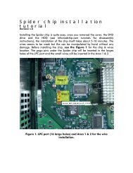
Installing the Spider chip is quite easy, once you removed the cover, the DVDdrive and the HDD, the installation of the chip itself takes about 5-10 minutes.The wires seem to be weak but they can be manipulated by hand without anydamage. Before installing the chip, see Figure 1 for the chip & wire locations.The pogo pins under the Spider chip will be inserted in the large holes of theLPC port and the small wires will be inserted in the Area 1 & 2 for <strong>Xbox</strong> 1.6 andin the Area 2 only for <strong>Xbox</strong> 1.0 to 1.5.Figure 1. LPC port (16 large holes) and Area 1 & 2 for the wire installation.w w w . s p i d e r c h i p . c o m 1
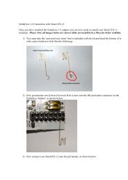
SPIDERCHIPVersion Comparaison(connectors)SpiderChip v1.0SpiderChip v1.1w w w . s p i d e r c h i p . c o m 2
Before installing the wires in the small holes, you must secure the chip usingthe screw (provided). Remove the Torx screw (T10) from the board (besideLPC) and place the metal washer (provided). Put the chip over the washer, thenplace the screw provided with the chip. When you apply force to the screw,make sure that you keep the pogo pins of the chip aligned on the LPC at thesame time (see Figure 2). Don’t try to make the chip <strong>com</strong>pletely flat on themainboard, even when the screw is in place, the chip is not <strong>com</strong>pletely flat onthe board.Figure 2. Screwing the chip and alignment on the LPC port.Once the chip is in place, you can put the wires in the small holes(Area 1 & 2 on Figure 1).w w w . s p i d e r c h i p . c o m 3
The Figure 3 shows the wire identification on the Spider chip.Place them using the following order: A-B-C-D-E.DEA B CFigure 3. Wire identification on the chip.Place the wires in the small holes (called via) on the <strong>Xbox</strong> mainboard. Use thepictures shown in Figures 4 to 7, depending on your <strong>Xbox</strong> version. Youshould be able to place the wires with your fingers. If not, make sure that youuse small tweezers and also that only a small force is applied on the wires. Anexcessive force or inappropriate tooling can damage the wires.w w w . s p i d e r c h i p . c o m 4
IMPORTANT NOTE: For <strong>Xbox</strong> 1.6, all the wires are needed while only the Dwire is needed for <strong>Xbox</strong> 1.0-1.5. In these <strong>Xbox</strong> versions, the D wire is insertedin the D0 via. You can cut the unused wires or insulate them with a piece ofnon-conductive tape. For <strong>Xbox</strong> 1.6, don’t cut any wire, they are all needed!w w w . s p i d e r c h i p . c o m 5
For <strong>Xbox</strong> versions 1.0 & 1.1, use this location in Area 2 to insert the D wire:Figure 4. Wire location in Area 2 for <strong>Xbox</strong> 1.0-1.1.For <strong>Xbox</strong> versions 1.2 to 1.5, use this location in Area 2 to insert the D wire:Figure 5. Wire location in Area 2 for <strong>Xbox</strong> 1.2-1.5.w w w . s p i d e r c h i p . c o m 6
If you have a version 1.6 <strong>Xbox</strong>, use figures 6 and 7 to insert the wires of theArea 1 & 2.Figure 6. Wire location in Area 1 (<strong>Xbox</strong> 1.6).w w w . s p i d e r c h i p . c o m 7
Figure 7. Wire location in Area 2 (<strong>Xbox</strong> 1.6).Make sure that the wires in the Area 2 are placed in order: C-D-E and also thatthey don’t touch each other.After the insertion of the wires, the installation should look like this:Figure 8. Actual placement of the wires in the Area 1 (<strong>Xbox</strong> 1.6).w w w . s p i d e r c h i p . c o m 8
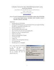
Figure 9. Actual placement of the wires in the Area 2 (<strong>Xbox</strong> 1.6).You can now plug the switch provided with the Spider. If you don’t want to plugthis external switch, the chip will work but will be in ‘always on’ mode. If youconnect the switch, you will have the choice between your original bios and thebios of your Spider. Route the wires of the switch through you <strong>Xbox</strong> cover sideholes and the chassis slots (see figure 10). You can place the switch outsidethe <strong>Xbox</strong> using the sticker under the switch.IMPORTANT NOTE: The socket of this wire is very fragile and if you want tounplug the switch from the chip, please use extreme care!w w w . s p i d e r c h i p . c o m 9
Make a last check: make sure that no wires touch each other and that the chip isaligned on the LPC port. Power on the <strong>Xbox</strong> and see if the LED lights up as shown inFigure 10. If the light is on, it doesn’t mean that all the wires are properly placed,it just means that the chip receives power from the <strong>Xbox</strong>. To make sure that all thewires are well inserted, plug the <strong>Xbox</strong> on your TV (even if there is no DVD or HDDin the <strong>Xbox</strong>) and see if there is a booting animation. When the chip is disabled, youwill see the normal booting animation. When the chip is enabled, you should get ascreen that shows the Cromwell bios disk request. If you can see that, you cannow reassemble the <strong>Xbox</strong> and go to the second tutorial: How to flash aSpider chip using a disk.Figure 10. Spider chip blue LED when the <strong>Xbox</strong> is powered up.w w w . s p i d e r c h i p . c o m 10